Table of Contents
Advertisement
FLASH MEMORY MULTIMEDIA AV NAVIGATION RECEIVER
AVIC-F700BT
AVIC-F7010BT
NAVIGATION AV SYSTEM
AVIC-F700BT
This service manual should be used together with the following manual(s):
Model No.
Order No.
CX-3195
CRT3815
For details, refer to "Important Check Points for Good Servicing".
PIONEER CORPORATION
PIONEER ELECTRONICS (USA) INC. P.O. Box 1760, Long Beach, CA 90801-1760, U.S.A.
PIONEER EUROPE NV Haven 1087, Keetberglaan 1, 9120 Melsele, Belgium
PIONEER ELECTRONICS ASIACENTRE PTE. LTD. 253 Alexandra Road, #04-01, Singapore 159936
PIONEER CORPORATION 2008
Mech.Module
S10.5COMP2
CD Mech. Module : Circuit Descriptions, Mech. Descriptions, Disassembly
4-1, Meguro 1-chome, Meguro-ku, Tokyo 153-8654, Japan
AVIC-F700BT/XS/UC
/XS/UC
/XS/EW5
Remarks
K-ZZZ.-001 MAY 2008 Printed in Japan
ORDER NO.
CRT4157
/XS/UC
Advertisement
Table of Contents

Related Manuals for Pioneer AVIC-F700BT/XS/UC


Summary of Contents for Pioneer AVIC-F700BT/XS/UC
- Page 1 PIONEER CORPORATION 4-1, Meguro 1-chome, Meguro-ku, Tokyo 153-8654, Japan PIONEER ELECTRONICS (USA) INC. P.O. Box 1760, Long Beach, CA 90801-1760, U.S.A. PIONEER EUROPE NV Haven 1087, Keetberglaan 1, 9120 Melsele, Belgium PIONEER ELECTRONICS ASIACENTRE PTE. LTD. 253 Alexandra Road, #04-01, Singapore 159936 PIONEER CORPORATION 2008 K-ZZZ.-001 MAY 2008 Printed in Japan...
-
Page 2: Safety Information
1. During repair or tests, minimum distance of 13 cm from the focus lens must be kept. 2. During repair or tests, do not view laser beam for 10 seconds or longer. CAUTION: USE OF CONTROLS OR ADJUSTMENTS OR PERFORMANCE OF PROCEDURES OTHER THAN THOSE SPECIFIED HEREIN MAY RESULT IN HAZARDOUS RADIATION EXPOSURE. AVIC-F700BT/XS/UC... - Page 3 Transistors Q101 in PCB drive the laser diodes. When Q101 is shorted between their terminals, the laser diodes will radiate beam. If the top cover is removed with no disc loaded while such short-circuit is continued, the naked eyes may be exposed to the laser beam. AVIC-F700BT/XS/UC...
- Page 4 To protect products from damages or failures during transit, the shipping mode should be set or the shipping screws should be installed before shipment. Please be sure to follow this method especially if it is specified in this manual. AVIC-F700BT/XS/UC...
-
Page 5: Table Of Contents
10.5 AV UNIT(RGB LED DRIVER SECTION) ....................112 10.6 AV UNIT(IF SECTION)(GUIDE PAGE)....................114 10.7 KEYBOARD UNIT ..........................120 10.8 CD MECHANISM MODULE(GUIDE PAGE)..................122 10.9 WAVEFORMS............................128 11. PCB CONNECTION DIAGRAM ........................130 11.1 AV UNIT ..............................130 11.2 KEYBOARD UNIT..........................134 11.3 CD CORE UNIT(S10.5COMP2) ......................136 12. ELECTRICAL PARTS LIST.........................138 AVIC-F700BT/XS/UC... -
Page 6: Service Precautions
Eject Lock: ON The Bluetooth word mark and logos are owned by the Bluetooth SIG, Inc. and any use of such marks by Pioneer Corporation is under license. Other trademarks and trade names are those of their respective owners. AVIC-F700BT/XS/UC... -
Page 7: Notes On Soldering
Compared with eutectic solders, lead-free solders have higher bond strengths but slower wetting times and higher melting temperatures (hard to melt/easy to harden). The following lead-free solders are available as service parts: Parts numbers of lead-free solder: GYP1006 1.0 in dia. GYP1007 0.6 in dia. GYP1008 0.3 in dia. AVIC-F700BT/XS/UC... -
Page 8: Specifications
2. SPECIFICATIONS 2.1 SPECIFICATIONS AVIC-F700BT/XS/UC... - Page 9 AVIC-F700BT/XS/UC...
- Page 10 AVIC-F700BT/XS/UC...
-
Page 11: Disc/Content Format
2.2 DISC/CONTENT FORMAT AVIC-F700BT/XS/UC... -
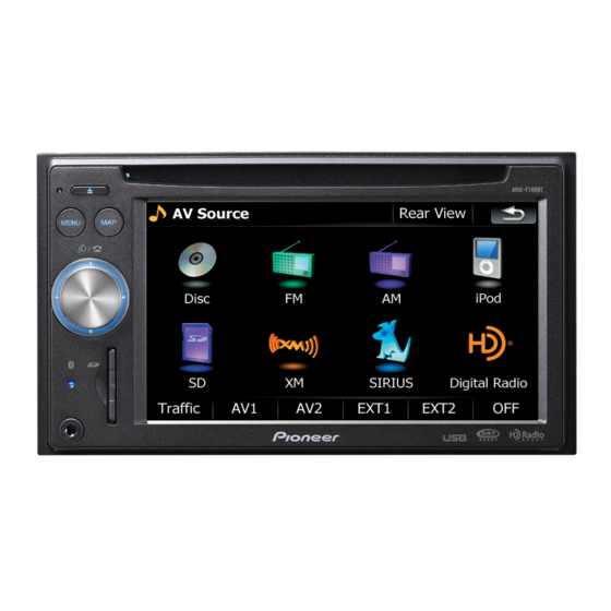
Page 12: Panel Facilities
2.3 PANEL FACILITIES AVIC-F700BT/XS/UC... - Page 13 AVIC-F700BT/XS/UC...
- Page 14 AVIC-F700BT/XS/UC...
-
Page 15: Connection Diagram
2.4 CONNECTION DIAGRAM AVIC-F700BT/XS/UC... - Page 16 AVIC-F700BT/XS/UC...
-
Page 17: Basic Items For Service
See the table below for the items to be checked regarding video and audio: Item to be checked regarding video Item to be checked regarding audio Disturbed image (video jumpiness) Volume too high Mottled color AVIC-F700BT/XS/UC... -
Page 18: Pcb Locations
3.2 PCB LOCATIONS Keyboard Unit AV Unit CD Core Unit(S10.5COMP2) Unit Number CWN3170(UC) Unit Number CWN3168(EW5) Unit Name AV Unit Unit Number Unit Name Keyboard Unit Unit Number CWX3514 Unit Name CD Core Unit(S10.5COMP2) AVIC-F700BT/XS/UC... -
Page 19: Jigs List
AV Unit <---> CD Mechanism Module Test Disc TCD-782 Checking the grating L.P.F. Checking the grating (Two pieces) Service Data Disc GGV1322 for Test Mode, Test Disc - Grease List Name Grease No. Remarks Grease GEM1024 CD Mechanism Module Grease GEM1045 CD Mechanism Module AVIC-F700BT/XS/UC... -
Page 20: Cleaning
Before shipping out the product, be sure to clean the following portions by using the prescribed cleaning tools: Portions to be cleaned Cleaning tools CD pickup lenses Cleaning liquid : GEM1004 Cleaning paper : GED-008 Portions to be cleaned Cleaning tools Fans Cleaning paper : GED-008 AVIC-F700BT/XS/UC... - Page 21 AVIC-F700BT/XS/UC...
-
Page 22: Block Diagram
LCJ1 FRONT OUTPUT FM/AM SUBWOOFER OUTPUT SYSTEM REMOTE CONTROL LCD MODULE AUDIO INPUT CWX3611 VIDEO INPUT1 REAR MONITOR OUTPUT REAR CAMERA INPUT ANT1 AVIC-F700BT/XS/EW5 :CDP1092 FM/AM ANT AVIC-F700BT/XS/UC :CDP1143 AVIC-F7010BT/XS/UC TOUCH PANEL CWX1136 CD ME LCD MODULE ASSY CXC8914 AVIC-F700BT/XS/UC... - Page 23 IP BUS CORD ASSY AV UNIT PS/IF SECTION A/V SECTION POWER SUPPLY FM/AM TUNER UNIT TERMINALS TUNER SECTION PULSE SYSTEM uCOM SECTION AANT RGB LED DRIVER SECTION CN1005 IF SECTION ANT1401 CN701 FM/AM ANTENNA IN CN701 CD MECHANISM MODULE AVIC-F700BT/XS/UC...
-
Page 24: Block Diagram
Reverse Signal Input Arrange to CPLD(NAV Reverse Signal Input An Answer of Power off Waveform Reverse Signal Acc/Bup/ILM Sence Control Signal Power Supply CONN VCC 5 V DC/DC Switch Speed Pulse Input Speed Pulse Speed Pulse CONN Digital Out CONN AVIC-F700BT/XS/UC... -
Page 25: Navigation Unit
Digital Out CONN comp2) Front Panel posite In (2) Key Pad Volume Controller Board Buttons 1. Eject 2. Menu 3. Map 4. Mute AuX-in T(2) BT Antenna t Signal Watchdog wer off to CPLD(NAVI BD) rse Signal d Pulse AVIC-F700BT/XS/UC... - Page 26 HRHSLK RDS57K GUIDEMUTE NOSELR NOSELR X601 XOUT 20.000MHz TEMP SENSOR TH601 SELSCL SELSDA TEMPIN SREMOTE Q2860 IC604 TC7S32FU MUTE SRCM IC608 BD5335FVE CN701 RESET VOUT BRST,BRXEN,BSRQ,BDATA,BSCK IC603 TC7SH04FUS1 ILMSNS ILLSNS ASENS RESET CDRESET CDRESET TEIN VD(7.5V) VDD(3.3V) CD3.3 LOUT AVIC-F700BT/XS/UC...
- Page 27 CN1001 AVIC-F700BT/XS/EW5 NAVI5V AVIC-F700BT/XS/UC AVIC-F7010BT/XS/UC O 2/2 AV8V FAN DRIVER FU4771 FANCONT FANV Q4771 FANUP ASENS Q4776 EVOL PWR AMP IC4271 IC1007 CN1005 PML018A PAL007C IN5+_L Frout_L IN4 OUT4+ OUT4- IN4+_L Rear_L IN2 OUT2+ OUT2- SREMOTE STBY MUTE AANT ANTB...
- Page 28 IC601 TC7SH08FUS1 Q2811 RSTOUT NAVIC SWACPW Q4738 Q2812 BSENSN Q4731 BSENS Q4733 ILMV Q4631 FU4631 ILMV Q4632 SYSPW Q2882 SWVDD5 VDD5 Q4754 SYSPW 3.3V NAVI3V Q2881 R658 R655 R651 SYSPW SIMUKE0 Q4753 SIMUKE1 SIMUKE2 SIMUKE3 SIMUKE4 R657 R654 R650 AVIC-F700BT/XS/UC...
- Page 29 NAVIC IC1008 NJM2125F Q4733 VDD5 IC4701 KBUP VDD5 KBUP BD3931HFP UVDD5 NKBUP CD3.3 IC4702 CD3.3 VDD5 NJM2885DL1-33 AVIC-F700BT/XS/EW5 B AVIC-F700BT/XS/UC UVDD5 AVIC-F7010BT/XS/UC R658 R655 R651 R647 R644 SIMUKE4 SIMUKE3 SIMUKE2 SIMUKE1 SIMUKE0 D TO 1/2 R643 R644 R646 R647 R650...
- Page 30 Phase-B ROTARY COMMANDER S803 ROT1 Phase-A Enc-Com KEY1 INT_KEY1 PANEL UNIT OTJ2 PUSH PUSH S805 CN803 D815 NAVI UNIT BL-LED BTJ2 ILMV BT-ANT D801 ANT801 ILMR RF_I/O ILMG ILMB CN802 AUX-V AUX-G AUX-AG AUX-VG AV MINI JACK IN AUX-L AVIC-F700BT/XS/UC...
- Page 31 TRACKING ACT. DIODE IC301 IC201 BA5839FP Q102 TD,FD PE5547A SD,MD /PUEN CN701 SPINDLE MOTOR /RESET /RESET LOEJ LOEJ CLCONT CLCONT LCOP CARRIAGE LOAD/ BRST,BRXEN,BSRQ MOTOR CONT LCOM CONT BDATA,BSCK 12EJ DSCSNS HOME S904 S905 S901 12EJ HOME S903 DSCSNS VDSENS AVIC-F700BT/XS/UC...
-
Page 32: Power Supply System Figure
427 mA TMC/VICS/MSN/Direct VT8(8 V) Tuner Front step amplifier BA00CC0WFP FM/AM Tuner DCSKIPCD Front step amplifier 25.4 mA FM/AM TUNER 172 mA typ 172 mA BA00CC0WFP UNIT max 200 mA X-2026 SYSPW or typ 103 mA SWACPW max 140 mA AVIC-F700BT/XS/UC... - Page 33 MS5 ->SYS RQ(WDT,IRQ) RST INV OR MUTE CIRCUIT 3 -> 5AND IPD T08T TC74VHCT32T TC7WH32FU TC74SH04 TC7S32FU TC7SET08FU 2 mA 2 mA 2 mA 2 mA 2 mA _LED DRIVER AV SELECTOR TEMPERATURE CIRCUIT 343&UMX1N 3 mA 08FT irect mplifier AVIC-F700BT/XS/UC...
- Page 34 CD Source OFF 20 mA CD 7.5 V(S10.5) VDCONT FCONT ILMV 30 mA ILMV 9 V SYSPW NAVI 3.3 V max 2.5A KMOD TR SYSPW PKB SNS NAVI 5 V NAVICO FCONT SYS->NAVI SYS->NAVI DCSKIP TC7SH08FU TC74VHCT08 NAVI, LCD BORD AVIC-F700BT/XS/UC...
- Page 35 8.4 mA 1 mA CAPTAIN6 37 mA NJM2125 50 mA GUIDE MIX AV SELECTOR 9 mA NJM2060V AN15887A MUTE CIRCUIT PKB SNS SYS->NAVI TC74VHCT08FTS1 KEY BORD AVIC-F700BT/XS/UC...
-
Page 36: Diagnosis
AUDIO CONTROL SYSPW DCSKIPCD ANTON POWER SUPPLY ANTON (Source interlocking CONTROL movement, forced OFF) SWACPW DCSKIP BSENSN RSTOUT NAVI CONTROL BATFAULT CPUWDT OFFINFO OFFANS NAVI POWER NAVICON SUPPLY (At the time of a reset start) CONTROL FANCONT FAN CONTROL AVIC-F700BT/XS/UC... - Page 37 MAIN LOOP After mute (300 ms) (After SYSPWR ON, at least 300 ms. MUTE time is extended to OFFANS Low henceforth.) 8 ms to 16 ms or more R SUPPLY MASK(200 ms) 16 ms FANCONT(At the time of high temperature) AVIC-F700BT/XS/UC...
-
Page 38: Error Code List
Remarks: Mechanical errors are not displayed (because a CD is turned off in these errors). Unreadable TOC does not constitute an error. An intended operation continues in this case. Upper digits of an error code are subdivided as shown below: 1x: Setup relevant errors, 3x: Search relevant errors, Ax: Other errors. AVIC-F700BT/XS/UC... -
Page 39: Connector Function Description
11. SWR 11. IPL- 12. ILM 12. BREM 13. AANT 13. SWL 14. ACC 14. SWGND 15. GND 15. VTR1R 16. BUP 16. VTR1RGND 17. VTR1L 18. VTR1LGND 19. VTR1V 20. VTR1VGND 21. REARVOUT 22. GNDV 23. BCV 24. BCVGND AVIC-F700BT/XS/UC... -
Page 40: Troubleshooting
20 - Connector of AV unit: 3 V seconds. Power supply LCD backlight is OK? LCD unit failure. block for "LCD Panel unit" is OK? No Display (White or Gray screen) NAVI unit failure. LCD Panel unit failure. AVIC-F700BT/XS/UC... - Page 41 Pin1 Pin1 Pin10 Pin1: TFT_ANODE Power supply Pin36: LVDSN Video signal (LVDS) from NAVI to LCD BD. Pin2: TFT_ANODE2 from LCD BD to Pin37: LVDSP Video signal (LVDS) from NAVI to LCD BD. Pin6: TFT_CATHODE LCD unit Pin7: TFT_CATHODE AVIC-F700BT/XS/UC...
- Page 42 Pin12: ROT1 KEY (Rotary) signal from KEY BD to LCD BD (Pulse waveform) Pin33: ROT0 KEY (Rotary) signal from KEY BD to LCD BD (Pulse waveform) Pin34: ROT1 KEY (Rotary) signal from KEY BD to LCD BD (Pulse waveform) AVIC-F700BT/XS/UC...
- Page 43 Case 5 Audio (NAVI SOURCE) or Guide voice (BEEP sound) is NG. Pin19: GUI_P Guidance or BEEP sound Pin28: NAVI L Audio Lch Pin30: NAVI R Audio Rch Pin29,31: GND AVIC-F700BT/XS/UC...
-
Page 44: Service Mode
3. Insert the SD card into the main unit. 4. Turn ACC ON. 5. The test mode menu is displayed. << Enter the test mode in the set procedure. >> Start screen When the set procedure is followed (Procedure OK) AVIC-F700BT/XS/UC... - Page 45 Not for service DTV Test Not for service SD Test SD card test EQ Flat/Vo Not for service RGB Illumin Not for service BT Test Not for service Screen Not for service BAK CTL Adjustment of the LCD backlight AVIC-F700BT/XS/UC...
- Page 46 • • • [Stereo] Output of stereo • • • [OK] Terminate Audio Test. • • • Gps Viewer Execution Screen Starttest << Operation method >> 1. Select ‘Start Type’. Normally, ‘Hot’. 2. Press ‘Start’ to start the test. AVIC-F700BT/XS/UC...
- Page 47 1. When GPS Running is green, the test is started. 2. When Valid Position is green, the measurement is successfully conducted. Signal << Operation method >> 1. The screen will be in this state if the test is not started. 2. To start the test, press ‘hot’. AVIC-F700BT/XS/UC...
- Page 48 1. When the test starts and a satellite is started to be acquired, the screen will be in this state. Not acquired. Yellow Already acquired. Green Acquired and data obtained. • • • • • • • • • AVIC-F700BT/XS/UC...
- Page 49 TMC measurement selection screen GpsTmcDemo << Test Content >> The TMC error rate can be measured. The frequency can be changed by tapping ‘<’ or ‘>’. The test can be terminated by tapping the left ‘x’ mark. AVIC-F700BT/XS/UC...
- Page 50 1. The screen will be in this state after started. 2. Press ‘Test’ to start the test. << Operation method >> 1. The menu appears when ‘Test’ is pressed. Select the item to test. << Operation method >> 1. To terminate the test, press ‘File’ and then ‘Exit’. AVIC-F700BT/XS/UC...
- Page 51 Clear the display of the version of microcomputer, ROM, and mecha. • • • [GetDeviceID] Display the device ID. • • • Touch Panel Test screen Start screen << Key operation >> [Calibration] Conduct calibration. • • • [Touch panel test] Conduct touch panel test. • • • AVIC-F700BT/XS/UC...
- Page 52 Touch panel calibration can be conducted by tapping five ‘+’ marks. Touch Panel Test << Key operation >> A line appears when a line is drawn by a finger on the touch panel. The test can be terminated by pressing the top right ‘x’ mark. AVIC-F700BT/XS/UC...
- Page 53 [Clear] Clear the display. • • • [High] Not for service • • • [Low] Not for service • • • SD Card Test screen Start screen << Key operation >> [Start] Start the test. • • • AVIC-F700BT/XS/UC...
- Page 54 • • • Notes) No operation can be conducted after this operation. Make a recovery by turning ACC OFF ON. [Backlight on] The backlight turns on. • • • [Set] The brightness of the backlight can be changed. • • • AVIC-F700BT/XS/UC...
- Page 55 2. Then, tap the bottom left of the screen, and the screen will be as shown below. Tap ‘Keyboard’. << Key operation >> 3. When the keyboard appears, tap the edit box again to make it active. Then input by keyboard becomes possible. Enter a desired number and tap ‘Set’ to change the brightness of the backlight. AVIC-F700BT/XS/UC...
-
Page 56: Cd Test Mode
1k ohms in series. The load and eject operation is not guarantied with the mechanism upside down. If the mechanism is blocked due to mistaken eject operation, reset the product or turn off and on the ACC to restore it. AVIC-F700BT/XS/UC... - Page 57 If the operation is completed successfully, the screen shifts to test mode screen after (3) is pressed long The test mode is released by ACC-OFF operation SlaveTestMode DVD(CD) region display DVD(CD) debug display DVD(CD) touch direct display Back Shift to selected test mode. AVIC-F700BT/XS/UC...
- Page 58 • When the power is turned on/off the jump mode is reset to the Single TR (91) while the gain of the RFAMP is reset to 0 dB. At the same time all the self-adjusting values shall return to the default setting. AVIC-F700BT/XS/UC...
-
Page 59: Uboot Menu
Coice: 1 Image Region Checksum = 0x64463447 Read Progress : 31% CE Upgrade OK Please restart your device!! <WINCE Upgrade Menu:Progress Screen> <WINCE Upgrade Menu:Finish Screen> 4. After the menu of “WINCE Upgrade” show “CE Upgrade OK”, restart the device. AVIC-F700BT/XS/UC... -
Page 60: Using The Test Disc
1. This screen appears when the Test Disc is activated. 2. Tap ‘E-MIC’ to start the test. << Operation method >> 1. This screen appears when the test is started. 2. Put a sound into the microphone while this screen is shown. The sound is recorded. AVIC-F700BT/XS/UC... - Page 61 1. When this screen appears, the recorded sound is played ‘quietly’. Notes) The sound volume cannot be adjusted. << Operation method >> 1. When this screen appears, the recorded sound is muted. Notes) The sound volume cannot be adjusted. AVIC-F700BT/XS/UC...
- Page 62 1. This screen appears when the Test Disc is activated. If you tap "GPS_TTFF", the test is started. << Operation method >> 1. When the test is started, this screen is displayed. When you terminate the test in the way, tap the "Exit". AVIC-F700BT/XS/UC...
- Page 63 If you go to next step, tap "OK". Version Check << Operation method >> 1. This screen appears when the Test Disc is activated. 2. When ‘Version’ is tapped, the test starts. If the "Reality" corresponds to "Plan", the result becomes "OK". AVIC-F700BT/XS/UC...
- Page 64 If the test result is "OK", the blue screen is displayed. "Reality" is each version on actual machine and the "Plan" is the version information described in "Information.txt" of SD card. << Operation method >> If the test result is "NG", the red screen is displayed. AVIC-F700BT/XS/UC...
- Page 65 2. If you tap the "Restore", the user data is deleted. << Operation method >> If the deletion is terminated, this screen is displayed. Notes:) "Splash screen setting" is not back to default after performing this function. Please set the "Splash screen setting", before performing this function. AVIC-F700BT/XS/UC...
-
Page 66: Disassembly
Case. Note) To remove the screws, use jig No. GGK1068. Fig.1 Removing the CD Mechanism Module (Fig.2) Remove the four screws. Disconnect the connector on the back and then remove the CD Mechanism Module. CD Mechanism Module Fig.2 AVIC-F700BT/XS/UC... - Page 67 Disconnect the three connectors and then remove the Monitor Assy. (Right side) Monitor Assy (Left side) (Top side) Fig.3 Monitor Assy Removing the Navi Unit (Fig.4) Navi Unit Remove the five screws. Disconnect the four connectors and then remove the Navi Unit. Fig.4 AVIC-F700BT/XS/UC...
- Page 68 Remove the three screws and then remove the Chassis(Upper). (Right side) Chassis(upper) Remove the FFC(CDE8552). (Left side) Remove the cord assy(CDE8393). AV Unit Remove the cord assy(CDH1381). Remove the screw. Remove the six screws and then remove the AV Unit. Fig.5 AVIC-F700BT/XS/UC...
- Page 69 Panel Unit Fig.6 Removing the Keyboard Unit (Fig.7) LCD Module Assy Remove the four screws. Release the five latches and then remove the LCD Module Assy. Keyboard Unit Remove the four screws and then remove the Keyboard Unit. Fig.7 AVIC-F700BT/XS/UC...
- Page 70 Upper Frame. 3. While lifting the Carriage Mechanism, remove it from the three Dampers. Caution: When assembling, be sure to apply some alcohol to the Dampers and assemble the mechanism in a clamped state. Damper Damper Carriage Mechanism Lower Frame AVIC-F700BT/XS/UC...
- Page 71 Assemble the sub unit side of the Pickup, taking the plate (Chassis) in-between. When treating the leads of the Load Carriage Motor Assy, do not make them loose over the Feed Screw. Poly Washer Change Arm Pickup Lock Arm Inner Holder Feed Screw Planet Gear Pickup Rack Chassis Pickup AVIC-F700BT/XS/UC...
- Page 72 Demount LCD PANEL ASSY by extending snap fits on the grille side. Snap fit 2 place Do not bend CND4319 Do not bend CND4319 Remove snap fits by extending them on the grille side using tweezers or bamboo tweezers. AVIC-F700BT/XS/UC...
- Page 73 • The code assy connecting 1F AV UNIT and 2F NAVI UNIT (CDE8393) shall be fitted on the back side of the choke coil (CTH1347) after 1F Chassis Unit and 2F Chassis Unit are fixed, as shown below. CDE8393 CTH1347 AVIC-F700BT/XS/UC...
- Page 74 CSX1135 shaft of an encoder CXC8994 CXC8995 • Since two case (CNB3472) fixing screws are ‘TORX tamper’ (tamper-proof screws with a projection in TORX), a special tool is required. TORX screwdriver(T8) : GGK1068 Mark 1 (T8 size) M2.6 thread AVIC-F700BT/XS/UC...
-
Page 75: Each Setting And Adjustment
Because of eccentricity in the disc and a slight misalignment of the clamping center the grating waveform may be seen to "wobble" ( the phase difference changes as the disc rotates). The angle specified above indicates the average angle. Hint Reloading the disc changes the clamp position and may decrease the "wobble". AVIC-F700BT/XS/UC... - Page 76 Ech → Xch 20 mV/div, AC Grating waveform Fch → Ych 20 mV/div, AC 0 degrees 30 degrees 45 degrees 60 degrees 75 degrees 90 degrees AVIC-F700BT/XS/UC...
-
Page 77: Av Unit Adjustment
8.2 AV UNIT ADJUSTMENT - Adjustment point AV UNIT(SIDE A) VR4231 AV UNIT(SIDE B) V1VG(GND) AV CONNECTOR CN1016 AVIC-F700BT/XS/UC... - Page 78 AVIC-F700BT/XS/UC...
-
Page 79: Flicker Adjustment
8.3 FLICKER ADJUSTMENT AVIC-F700BT/XS/UC... -
Page 80: Exploded Views And Parts List
Screw adjacent to mark on the product are used for disassembly. For the applying amount of lubricants or glue, follow the instructions in this manual. (In the case of no amount instructions,apply as you think it appropriate.) 9.1 PACKING AVIC-F700BT/XS/UC... - Page 81 31-6 Passport See Contrast table(2) Cushion CZN5473 31-7 Caution Card See Contrast table(2) Microphone CZX5059 (2) CONTRAST TABLE AVIC-F700BT/XS/UC, AVIC-F7010BT/XS/UC and AVIC-F700BT/XS/EW5 are constructed the same except for the following: Mark Description AVIC-F700BT/XS/UC AVIC-F7010BT/XS/UC AVIC-F700BT/XS/EW5 Unit Box CHG6484 CHG6573 CHG6482...
- Page 82 (3) OWNER’S MANUAL PARTS LIST AVIC-F700BT/XS/UC AVIC-F7010BT/XS/UC AVIC-F700BT/XS/EW5 Part No. Language Part No. Language Part No. Language CRB2684 English CRB2684 English CRB2700 English CRB2685 French CRB2685 French CRB2701 Spanish CRB2686 English CRB2686 English CRB2702 German CRB2703 French CRB2687 French CRB2687...
- Page 83 AVIC-F700BT/XS/UC...
-
Page 84: Exterior(1)
9.2 EXTERIOR(1) AVIC-F700BT/XS/UC... - Page 85 CTX1095 SD Unit CWX3652 Insulator See Contrast table(2) Screw(M2 x 2) CBA1771 Holder CND3758 (2) CONTRAST TABLE AVIC-F700BT/XS/UC, AVIC-F7010BT/XS/UC and AVIC-F700BT/XS/EW5 are constructed the same except for the following: Mark Description AVIC-F700BT/XS/UC AVIC-F7010BT/XS/UC AVIC-F700BT/XS/EW5 Knob Unit CXC8995 CXC8995 CXC8994 Grille Unit...
-
Page 86: Exterior(2)
9.3 EXTERIOR(2) (A) GYH1031(Mylay tape) * Hold the flexible cable to the shield on the Navi Unit. AVIC-F700BT/XS/UC... - Page 87 Chassis CNA3042 Cord Assy See Contrast table(2) Gasket CNN2529 Cover CND3917 Bracket CND4564 (2) CONTRAST TABLE AVIC-F700BT/XS/UC, AVIC-F7010BT/XS/UC and AVIC-F700BT/XS/EW5 are constructed the same except for the following: Mark Description AVIC-F700BT/XS/UC AVIC-F7010BT/XS/UC AVIC-F700BT/XS/EW5 Navi Unit(U1) CWX3641 CWX3641 CWX3639 Cord Assy...
-
Page 88: Exterior(3)
9.4 EXTERIOR(3) EW5 MODEL EW5 MODEL UC MODEL UC MODEL AVIC-F700BT/XS/UC... - Page 89 Cord CDE6825 CNS1472 Holder CND3695 Resistor RS1/2PMF102J Holder See Contrast table(2) Shield CND4320 (2) CONTRAST TABLE AVIC-F700BT/XS/UC, AVIC-F7010BT/XS/UC and AVIC-F700BT/XS/EW5 are constructed the same except for the following: Mark Description AVIC-F700BT/XS/UC AVIC-F7010BT/XS/UC AVIC-F700BT/XS/EW5 AV Unit CWN3170 CWN3170 CWN3168 Connector(CN1021) CKS3408...
-
Page 90: Cd Mechanism Module
9.5 CD MECHANISM MODULE AVIC-F700BT/XS/UC... - Page 91 Bracket CND2583 CND2584 Lever CND2585 CND2586 Bracket CND2587 CND2588 Lever CND2589 Holder CNV9522 Gear CNV7207 Gear CNV9513 Gear CNV7209 Gear CNV9514 Gear CNV9515 Gear CNV9516 Rack CNV9517 CNV7216 Roller CNV8189 Gear CNV9518 Guide CNV9519 Gear CNV7595 Guide CNV9520 CNV7805 AVIC-F700BT/XS/UC...
-
Page 92: Schematic Diagram
R2976 PKBOUT R2977 KMODEOUT KMODE R2978 REVSNS OFAN R2979 OFFANS3 OFFANS OFIN R2980 OFFINFO3 OFFINFO WDOG R2981 CPUWDT3 WDOG RESB R2982 RESETB RESETB PCHG PCHNG PULSE GNDD NAVI3GND NAVIRG FRVGND GUIDEG GNDV GNDA GNDRF FANGND GNDD GNDA GNDD GNDFM AVIC-F700BT/XS/UC... - Page 93 GNDD emergency MUTE GNDD GNDD 5.0V GNDD GNDD GNDA GNDD The > mark found on some component parts indicates the importance of the safety factor of the part. Therefore, when replacing, be sure to use parts of identical designation. AVIC-F700BT/XS/UC...
- Page 94 AVIC-F700BT/XS/UC...
- Page 95 AVIC-F700BT/XS/UC...
- Page 96 AVIC-F700BT/XS/UC...
- Page 97 AVIC-F700BT/XS/UC...
-
Page 98: Av Unit(A/V Section)(Guide Page)
R4156 R4157 C4153 R4151 100K 100K C4151 IC1016 220P BA4558RFVM (2/2) IC1016 R4152 BA4558RFVM C4152 (1/2) 2 1B 1 2C 2E 6 LPF AMP Q4312 ISOLATOR IMD3A GNDA 10.6kHz 18dB/oct D4311 DAN202K +4.6dB GNDA Rch MUTE GMUTE Normally Uttering AVIC-F700BT/XS/UC... - Page 99 4R7/16 GNDD D4355 TELMUTE L4351 R4351 DAN202U TELMUTE GNDA R4312 GNDD WIRED REMOTE(Black) L4371 WCONT CN1015 L4372 WIREIN 2 1B 1 2C 2E 6 Q4312 IMD3A GNDA D4311 D4312 DAN202K DAN202K GNDD Rch MUTE GMUTE Normally Hi Uttering Low AVIC-F700BT/XS/UC...
- Page 100 AVIC-F700BT/XS/UC...
- Page 101 AVIC-F700BT/XS/UC...
- Page 102 AVIC-F700BT/XS/UC...
- Page 103 AVIC-F700BT/XS/UC...
-
Page 104: Av Unit(Tuner Section)
2SC3127 GNDRF ANTENNA FM DISTRIBUTION L1403 8.3V ANT1401 RFIN CKX1060 C1401 C1402 L1402 C1405 Q1401 2SC3357 T1402 T1403 C1409 2200P T1401 R1412 3R3K 8.3V 8.0V 8.0V GNDRF VICS/TMC AMP CN1441 C1443 C1441 R1442 2200P Q1441 2SC3130 GNDRF GNDRF GNDRF AVIC-F700BT/XS/UC... - Page 105 TUNDO GNDRF GNDRF TUNDO GNDA TUNDI TUNDI 5.0V 5.0V VDD5 VDD5 GNDD 3.3V 3.3V 8.3V 8.3V 8.3V 8.3V 8.0V 8.0V 8.0V 8.0V 8.0V VICS8 VICS8 GNDRF GNDD GNDRF GNDA GNDD ILMGND GNDA ILMGND CN1441 GNDRF GNDRF GNDA GNDD GNDRF AVIC-F700BT/XS/UC...
-
Page 106: Av Unit(System Ucom Section)(Guide Page)
HRHSLK Q752 HRLK DTC124EUA HRDT GNDD HRCK RDSLK TC74VHC08FTS1 NAVI UART TC74VHCT08AFTS1 CTOSYS3 Q751 5 AND 3 AND DTC124EUA GNDD CTOSYS5 5.0V R618 R688 100K 100K C623 Q753 GNDD 100K DTC124EUA R689 GNDD NAVI LEVEL SHIFT Q754 DTC124EUA GNDD AVIC-F700BT/XS/UC... - Page 107 NOSELR NOSELR NOSELL NOSELL C621 VCC2 FANCONT FANCONT C4784 R4783 GNDD 3R3K L614 SWVDD5 C4785 R4784 3R3K 5.0V 5.0V 5.0V UVDD5 L613 CN601 GNDD TEMPIN GNDD TEMPIN R680 4R7K Q601 2SA1576A GNDD GNDD UVDD5 5.0V 5.0V 5.0V 5.0V 5.0V AVIC-F700BT/XS/UC...
- Page 108 AVIC-F700BT/XS/UC...
- Page 109 AVIC-F700BT/XS/UC...
- Page 110 AVIC-F700BT/XS/UC...
- Page 111 AVIC-F700BT/XS/UC...
-
Page 112: Av Unit(Rgb Led Driver Section)
10.5 AV UNIT(RGB LED DRIVER SECTION) RGB_LED DRIVER PART 5.0V 5.0V IC3601 GREEN BLUE M62343FP ILMGND 8.0V 8.0V 8.0V (RED) (GREEN) (RED) (BLUE) Q3604 Q3601 Q3602 Q3603 UMX1N UMX1N UMX1N UMX1N R3601 R3604 R3607 220K 220K 220K ILMGND AVIC-F700BT/XS/UC... - Page 113 AV UNIT(RGB LED DRIVER SECTION) GNDD GNDD SWVDD5 LEDCS 5.0V 5.0V LEDCK LEDDT ILB2 ILMB ILG2 ILMG ILR2 ILMR ILV2 8.0V ILMV 8.0V ILMGND R3629 (GREEN) (BLUE) ILMGND Q3605 Q3606 ILMGND GNDD UMX1N UMX1N AVIC-F700BT/XS/UC...
-
Page 114: Av Unit(If Section)(Guide Page)
L4642 KMODEOUT D1-1 D4643 OUTGND 150K RB083L-20 (10uH) PKBOUT PKBOUT D1-2 TRIP C4646 D2-1 VCC_SENSE R4654 180K COMP D2-2 (YB) C4648 RWMSKIP GNDD VREF5 STBY SP8K2 VREG5V_IN GNDD GNDD TPS5103IDB VDCONT Vref=1.185(V) GNDD FCONT Q4641 DTC114EUA GNDD GNDD GNDD AVIC-F700BT/XS/UC... - Page 115 GND2 CEK1254 Q4776 Q4773 2SA1587 2SD1760F5 IN1 2 5 IN2 GND1 1 6 OUT2 Q4632 R4773 ILMV GNDD GNDD D4771 RB500V-40 Q4772 D4772 ASENS RB500V-40 SYSPW DTC114EUA D4773 HZU8R2(B1) C4771 DTC114EUA FANUP Q4775 FAN DRIVER FANGND FANGND FANCONT FANV AVIC-F700BT/XS/UC...
- Page 116 AVIC-F700BT/XS/UC...
- Page 117 AVIC-F700BT/XS/UC...
- Page 118 AVIC-F700BT/XS/UC...
- Page 119 AVIC-F700BT/XS/UC...
-
Page 120: Keyboard Unit
D859 HZU11(B2) RGB ILM ILMV D860 HZU11(B2) ILMR D861 HZU11(B2) ILMG D862 HZU11(B2) ILMB D863 HZU5R6(B2) ROT0 R801 D864 HZU5R6(B2) ROT1 R802 GNDKEY D866 HZU5R6(B2) D867 HZU5R6(B2) D803 AUX-R AUX-L D804 AUX-AG AUX-V AUX-VG GNDKEY R850 GNDKEYGNDKEY CN802 GNDKEY AVIC-F700BT/XS/UC... -
Page 121: Menu Map
RB521S-30 KEY0 MENU 1.65 0.81 D810 R807 1R3K S803 Phase_A 10 Phase_B Enc_Com 9 Push R808 NAVI UNIT 6 GND BTJ2 CSX1135 R806 BT-ANT CN803 CTX1095 GNDKEY PUSH RF_I/O ROTARY COMMANDER ANT801 R810 D815 SMLE12BC7T(NP) C807 BT-ILM GNDKEY AV-IN AVIC-F700BT/XS/UC... -
Page 122: Cd Mechanism Module(Guide Page)
10.8 CD MECHANISM MODULE(GUIDE PAGE) PICKUP UNIT(P10.5)(SERVICE) SWITCHES: CD CORE UNIT(S10.5COMP2) S901:HOME SWITCH..ON-OFF S903:DSCSNS SWITCH..ON-OFF S904:12EJ SWITCH.....ON-OFF S905:8EJ SWITCH....ON-OFF The underlined indicates the switch position. M1 CXC7134 SPINDLE MOTOR M2 CXC4026 LOADING/CARRIAGE MOTOR CD DRIVER AVIC-F700BT/XS/UC... - Page 123 CD CORE UNIT(S10.5COMP2) SIGNAL LINE FOCUS SERVO LINE TRACKING SERVO LINE CARRIAGE SERVO LINE SPINDLE SERVO LINE CN701 & AVIC-F700BT/XS/UC...
- Page 124 AVIC-F700BT/XS/UC...
- Page 125 AVIC-F700BT/XS/UC...
- Page 126 AVIC-F700BT/XS/UC...
- Page 127 AVIC-F700BT/XS/UC...
-
Page 128: Waveforms
500 mV/div 2 ms/div 1 V/div s/div µ %RFAGC 500 mV/div 500 mV/div 500 mV/div 9TIN 500 mV/div Focus Search waveform Track Open waveform 1 Track Jump waveform Ref.: Ref.: Ref.: REFO REFO REFO Mode: Mode: Mode: TEST TEST TEST AVIC-F700BT/XS/UC... - Page 129 4LOEJ 312SNS 5 V/div 5 V/div 1 V/div 4LOEJ 0FIN 5 V/div 1 V/div 12 cm CD Eject operation 8 cm CD Eject operation Black dot(800 µm) during play Ref.: Ref.: Ref.: REFO Mode: Mode: Mode: Normal Normal Normal AVIC-F700BT/XS/UC...
-
Page 130: Pcb Connection Diagram
L1482 R1493 R763 L1483 R1433 R4239 C3613 C1485 IC3601 R4163 C4233 R4166 R3628 C1495 IC602 R4758 R2962 R2942 R621 R1496 L3601 C605 Q4751 R4751 L605 R761 C603 R4753 R2941 CN1000 CN601 C1023 C4751 IC605 Q4752 R4755 R4752 R4756 FRONT AVIC-F700BT/XS/UC... - Page 131 L611 R4163 R634 R663 R2980 R4166 L613 D4643 R664 R4657 R661 R2962 R2979 C4786 L1004 R2853 L2940 R2841 CN701 R2852 R2840 CN1000 C2843 C2840 FU4661 R2982 CN701 C2844 C4708 IC1002 R2983 D4701 Q2841 FU4641 R2846 NAVI UNIT FRONT OTJ1 AVIC-F700BT/XS/UC...
- Page 132 R4654 IC4641 R642 R697 R637 R680 R648 R695 C4645 R2884 R2883 R668 R4644 C4644 R4653 C4655 D4641 R733 Q2882 Q601 R712 R713 R711 L701 C4703 R4701 C4657 C4656 L702 R4628 C2841 R4678 C702 D4702 R716 Q2840 IC4702 D2840 R4641 AVIC-F700BT/XS/UC...
- Page 133 R4237 R1489 Q3604 R1494 Q3602 Q4232 C1497 R3618 R3621 C4703 R2944 C1489 R2953 R3627 L610 R1497 R3605 R2943 R3613 Q4753 R2954 R2945 C671 C702 R689 R618 R688 C1022 IC609 R2946 IC4702 R2940 IC601 C602 R602 C3608 R2959 L602 Q4754 AVIC-F700BT/XS/UC...
-
Page 134: Keyboard Unit
D809 R809 S802 S805 D810 D854 D855 R807 C801 D861 D858 C806 D857 D871 D801 D862 R810 D872 C805 R850 C804 D867 R802 C803 D866 D863 D869 D870 ROTARY COMMANDER S803 BT-ANTENNA ANT801 C807 D815 D805 D802 AV-IN CN802 AVIC-F700BT/XS/UC... - Page 135 KEYBOARD UNIT SIDE B D811 R808 D812 D856 D853 D852 C856 C854 D808 R805 D859 PANEL UNIT D860 OTJ2 D864 D868 CN801 C802 R803 R801 R806 D803 R804 D804 CN803 NAVI UNIT BTJ2 D806 D807 AVIC-F700BT/XS/UC...
-
Page 136: Cd Core Unit(S10.5Comp2)
11.3 CD CORE UNIT(S10.5COMP2) CD CORE UNIT(S10.5COMP2) SIDE A CN701 PICKUP UNIT(P10.5)(SERVICE) LOADING /CARRIAGE MOTOR SPINDLE MOTOR AVIC-F700BT/XS/UC... - Page 137 CD CORE UNIT(S10.5COMP2) SIDE B AVIC-F700BT/XS/UC...
-
Page 138: Electrical Parts List
(B,59,23) Transistor 2SC4081 IC 4171 (B,67,49) IC AN15887A Q 4232 (B,55,18) Chip Transistor 2SA1576A IC 4251 (B,103,107) IC NJM2505AF Q 4312 (B,77,39) Transistor IMD3A IC 4271 (B,68,73) IC PML018A Q 4314 (B,77,34) Transistor DTC323TK IC 4601 (B,118,65) IC TPS5103IDB AVIC-F700BT/XS/UC... - Page 139 (A,121,109) Diode DAN202U L 1422 (B,29,104) Inductor(EW5) LCTCR10K2125 D 4357 (A,107,119) Diode MALS068X L 1423 (B,44,88) Inductor(EW5) LCTAW101J2520 D 4358 (A,117,119) Diode MALS068X L 1441 (A,38,85) Inductor(EW5) LCTCR15K2125 D 4359 (A,121,119) Diode MALS068X L 1443 (A,44,83) Chip Coil(EW5) LCTAW1R0J2520 AVIC-F700BT/XS/UC...
- Page 140 RS1/16SS104J Y 1461 (A,17,93) FM/AM Tuner Unit(UC) CWE2098 R 689 (B,39,9) RS1/16SS104J (A,17,93) FM/AM Tuner Unit(EW5) CWE2127 R 690 (A,109,48) RS1/16SS472J > Fuse 10 A CEK1208 R 694 (A,113,47) RS1/16SS102J R 701 (B,106,6) RS1/16S221J RESISTORS R 702 (B,108,6) RS1/16S221J AVIC-F700BT/XS/UC...
- Page 141 (B,30,24) RS1/16S10R0D R 2964 (A,80,21) RS1/16SS0R0J R 2832 (A,27,35) RS1/16S2201D R 2967 (B,76,18) RS1/16SS0R0J R 2833 (A,32,27) (EW5) RS1/16S0R0J R 2968 (B,76,7) RS1/16SS0R0J R 2834 (B,37,30) RS1/16S104J R 2969 (B,77,7) RS1/16SS0R0J R 2860 (B,125,107) RS1/16SS391J R 2970 (B,79,14) RS1/16SS0R0J AVIC-F700BT/XS/UC...
- Page 142 R 4237 (B,57,18) RS1/16SS0R0J R 4615 (B,142,55) RS1/16S105J R 4240 (B,59,27) RS1/16SS0R0J R 4616 (B,92,99) RS1/8S222J R 4251 (B,101,113) RS1/16S750J R 4633 (A,128,85) RS1/16SS821J R 4252 (B,103,112) RS1/16SS473J R 4641 (B,140,8) RS1/4SA561J R 4643 (B,142,19) RS1/16S331J R 4253 (B,101,111) RS1/16SS473J AVIC-F700BT/XS/UC...
- Page 143 C 2800 (B,94,103) CKSRYB102K50 C 2801 (A,158,98) 100 uF/16 V CCH1565 C 601 (B,122,39) CKSRYB104K16 C 2802 (A,163,99) CCSRCH102J50 C 602 (B,44,5) CKSRYB104K50 C 2804 (A,163,101) CKSRYB104K50 C 604 (B,120,46) CKSRYB104K50 C 605 (A,39,13) CKSRYB104K16 C 2805 (B,93,101) CKSRYB104K50 AVIC-F700BT/XS/UC...
- Page 144 C 4156 (B,74,34) CKSSYB104K16 C 4281 (B,59,71) CKSRYB105K6R3 C 4157 (B,73,34) CCSSCH151J50 C 4284 (B,83,68) CKSRYB105K6R3 C 4158 (B,71,35) CCSSCH151J50 C 4285 (B,61,70) CKSRYB105K6R3 C 4159 (B,77,29) CKSQYB225K10 C 4286 (B,78,71) CKSRYB105K6R3 C 4160 (B,65,33) CCSSCH221J50 C 4287 (B,60,72) CKSRYB105K6R3 AVIC-F700BT/XS/UC...
- Page 145 CCG1223 D 866 (A,14,63) Diode HZU5R6(B2) D 867 (A,7,63) Diode HZU5R6(B2) C 4653 (A,150,32) 10 uF CCG1223 D 868 (B,5,69) Diode MALS068X C 4654 (A,157,32) 10 uF CCG1223 D 869 (A,5,58) Diode MALS068X C 4655 (B,133,22) 10 uF CCG1223 AVIC-F700BT/XS/UC...
- Page 146 C 239 (B,44,51) CCSSCH220J50 C 240 (A,35,61) CKSSYB104K10 R 206 (B,26,53) RS1/16SS104J C 250 (B,36,30) CKSSYB102K50 R 210 (B,13,32) RS1/16SS102J R 214 (B,36,34) RS1/16SS472J C 251 (B,33,29) CKSSYB102K50 R 216 (B,47,49) RS1/16SS472J C 303 (A,35,19) CKSSYB472K25 R 221 (B,36,32) RS1/16SS103J AVIC-F700BT/XS/UC...
- Page 147 CKSSYB223K16 C 307 (B,25,9) CKSRYB104K16 C 308 (B,10,27) CKSRYB105K10 C 703 (B,11,37) CCSSCH101J50 C 704 (B,8,36) CKSSYB102K50 C 711 (A,25,26) CKSSYB104K10 Miscellaneous Parts List Pickup Unit(P10.5)(Service) CXX1942 Motor Unit(SPINDLE) CXC7134 Motor Unit(LOADING/CARRIAGE) CXC4026 Navi Unit(UC) CWX3641 Navi Unit(EW5) CWX3639 AVIC-F700BT/XS/UC...
Need help?
Do you have a question about the AVIC-F700BT/XS/UC and is the answer not in the manual?
Questions and answers