DeWalt DW717 Manual
Hide thumbs
Also See for DW717:
- User manual ,
- Instruction manual (141 pages) ,
- Original instructions manual (145 pages)
Table of Contents
Advertisement
Advertisement
Table of Contents

Related Manuals for DeWalt DW717


Summary of Contents for DeWalt DW717
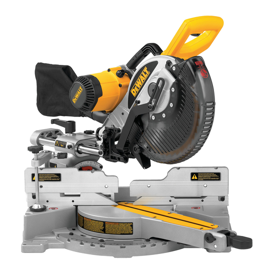
- Page 1 DW717 (220 Volt) 10" (254 mm) Double Bevel Sliding Compound Miter Saw...
-
Page 2: Table Of Contents
TABLE OF CONTENTS BRUSHES ..………………………………………………………………………………9 DOUBLE INSULATION/POLARIZED PLUG INSTRUCTIONS ........2 CONTROLS ........................9 SAFETY INSTRUCTIONS FOR ALL TOOLS ..…………………………………………2 OPERATION ..……………………………………………………………………………9 ADDITIONAL SAFETY RULES ..……………………………………………………….3 SWITCH ........................9 ELECTRICAL CONNECTION ..…………………………………………………………4 CUTTING WITH YOUR SAW .................10 ACCESSORIES ......................4 CROSSCUTS ......................10 BLADE DESCRIPTIONS ....................5 BEVEL CUTS ...................... -
Page 3: Double Insulation/Polarized Plug Instructions
• MAKE WORKSHOP CHILDPROOF with padlocks, master switches, or by removing Definitions: Safety Guidelines starter keys. The unauthorized start-up of a machine by a child or visitor may result in The definitions below describe the level of severity for each signal word. Please read injury. -
Page 4: Additional Safety Rules
• CHECK FOR DAMAGED PARTS. Before further use of the tool, a guard or other part • ALLOW THE MOTOR TO COME TO FULL SPEED prior to starting cut. Starting the that is damaged should be carefully checked to determine that it will operate properly cut too soon may cause damage to the machine or blade and/or serious injury. -
Page 5: Electrical Connection
WALT Industrial Tool Co., 701 East Joppa Road, Baltimore, MD filter out microscopic particles. 21286, call 1-800-4-D WALT (1-800-433-9258) or visit our website www.dewalt.com. • Avoid prolonged contact with dust from power sanding, sawing, grinding, WARNING: Since accessories, other than those offered by D WALT, have not been drilling, and other construction activities. -
Page 6: Blade Descriptions
Check the contents of your miter saw carton to make sure that you have received all parts. In addition to this instruction manual, the carton should contain: 1. One DW717 miter saw. 2. One D WALT 10" (254 mm) diameter saw blade. -
Page 7: Familiarization
45º bevel - Right IMPORTANT SAFETY INSTRUCTIONS Max. Height 1.2" (30 mm) Result Width 11.9" (302 mm) Changing or Installing a New Saw Blade (Fig. 3) Max. Width 12.6" (320 mm) Result Height 0.9" (22 mm) WARNING: To reduce the risk of serious personal injury, turn off the tool and disconnect it from the power source before attempting to move it, change accessories or make any Your saw is capable of cutting baseboard moldings 0.8"... -
Page 8: Transporting The Saw
TRIGGER FIG. 4 LIFTING SWITCH MOTOR HANDLE ENDCAP RAIL SET MOTOR OPERATING HANDLE SCREW HOUSING ADJUSTMENT BELT COVER RAIL LOCK KNOB BLADE BEVEL GUARD LOCK DUST SPOUT HANDLE SLIDE STOP BEVEL LATCH THUMBSCREW LEVER (one each side) BEVEL BEVEL LATCH SCALE PLATES KERF... -
Page 9: Miter Pointer Adjustment
MITER MITER POINTER ADJUSTMENT (FIG. 6) FIG. 5 FIG. 6 FIG. 9 POINTER Loosen the miter lock handle to move the miter arm to FENCE KNOB (one each side) the zero position. With the miter lock handle loose allow the miter latch to snap into place as you rotate the miter arm to zero. -
Page 10: Kerf Plate Adjustment
pry off the handle using a flat bladed screwdriver. Reorient KERF PLATE ADJUSTMENT identical D WALT brushes. Use of the correct grade of and install the handle such that it will hold the bevel when brush is essential for proper operation of electric brake. To adjust the kerf plates, loosen the screws holding the tightened. -
Page 11: Cutting With Your Saw
CUTTING WITH YOUR SAW FIG. 11 FIG. 13A If the slide feature is not used, ensure the saw head is pushed back as far as possible and the rail lock knob is tightened. This will prevent the saw from sliding along its rails as the workpiece is engaged. -
Page 12: Body And Hand Position
Another type of clamp may be supplied with material is cut laying flat). firmly bolted to a stable surface. your DW717. To purchase the DW7082 contact your local WARNING: The clamp foot must remain clamped above - EXAMPLES - retailer or D WALT service center. -
Page 13: Cutting Compound Miters
CUTTING COMPOUND MITERS FIG. 17 FIG. 19 A compound miter is a cut made using a miter angle and a bevel angle at the same time. This is the type of cut used to make frames or boxes with slanting sides like the one shown in Figure 16. -
Page 14: Special Cuts
INSIDE CORNER: FIG. 21 BEVEL SETTING TYPE OF CUT Left side LEFT SIDE, INSIDE CORNER: 1. Miter right at 45° 1. Top of molding against fence 33.85° Left 2. Save the right side of cut 2. Miter table set right 31.62° Right side 3. -
Page 15: Removing And Replacing The Belt
FIG. 24 CUTTING LARGE MATERIAL CAUTION: Continued use of a platform with sev- Occasionally you will encounter a piece of wood a little too eral kerfs may cause loss of material control and possible large to fit beneath the blade guard. If this occurs, simply injury. -
Page 16: Warranty
Patent Notification Troubleshooting Guide Manufactured under one or more of the following U.S. BE SURE TO FOLLOW SAFETY RULES AND INSTRUCTIONS patents: TROUBLE! WHAT’S WRONG? WHAT TO DO 6,823,765 6,101,914 5,907,987 5,375,495 SAW WILL NOT START 1. Saw not plugged in 1. -
Page 17: Table 1: Compound Miter Cut
TABLE 1 COMPOUND MITER CUT (Position wood with broad flat side on the table and the narrow edge against the fence.) SET THIS BEVEL ANGLE ON SAW... - Page 18 ‘ ’ DEWALT 080-515-0909 www.dewalt.co.kr Q&A ANSI Z87.1 (can/CSA Z94.3) ANSI S12.6 (S3.19) NIOSH/OSHA/MSHA (6’’(152.4mm) “ ” , 3- DEWALT 120V 0-25 26-50 51-100 101-150 220-240V 0-50 51-100 101-200 201-300 9 1 7...
- Page 19 Delete ? mark ’’ , 1121 Spring Lake Drive, Itasca, IL 60143-3201 . 120 ANSI 01.1 OSHA 1910.213 . 10 % DEWALT , DEWALT 834-46 080-515-0909 www.dewalt.co.kr DEWALT (CCA) DEWALT NIOSH/OSHA...
- Page 20 DW7080 DW7084 DW7082 DW7187 DWS7085 9 1 9...
- Page 22 9 2 1...
- Page 24 RAIL LOCK KNOB FIG. 10A SLIDE STOP 9 2 3...
- Page 26 9 2 5...
- Page 28 9 2 7...
Need help?
Do you have a question about the DW717 and is the answer not in the manual?
Questions and answers