Table of Contents
Advertisement
Advertisement
Table of Contents

Related Manuals for Panasonic MDF-DC700VX Series


Summary of Contents for Panasonic MDF-DC700VX Series
-
Page 1: Operating Instructions
Operating Instructions Ultra-Low Temperature Freezer MDF-DC500VX MDF-DC700VX MDF-DC500VX MDF-DC700VX Series MDF-DC700VX Please read the operating instructions carefully before using this product, and save the operating instructions for future use. See page 61 for all model numbers. -
Page 2: Table Of Contents
CONTENTS INTRODUCTION P. 2 PRECAUTIONS FOR SAFE OPERATION P. 3 LABELS ON UNIT P. 7 SYMBOLS ON UNIT P. 7 ENVIRONMENTAL CONDITIONS P. 8 INTENDED USE AND PRECAUTIONS P. 8 FREEZER COMPONENTS Unit P. 9 LCD touch panel P. 11 Remote alarm terminal P. -
Page 3: Introduction
INTRODUCTION ■ Read the operating instructions carefully before using the appliance and follow the instructions for safety operation. ■ Our company never guarantee any safety if the appliance is used for any objects other than intended use or used by any procedures other than those mentioned in the operating instructions. ■... -
Page 4: Precautions For Safe Operation
PRECAUTIONS FOR SAFE OPERATION It is imperative that the user complies with the operating instructions as it contains important safety advice. Items and procedures are described so that you can use this unit correctly and safely. If the precautions advised are followed, this will prevent possible injury to the user and any other person. - Page 5 PRECAUTIONS FOR SAFE OPERATION WARNING Do not use the unit outdoors. Current leakage or electric shock may result if the unit is exposed to rain water. Only qualified engineers or service personnel should install the unit. The installation by unqualified personnel may cause electric shock or fire. Install the unit on a sturdy floor and take an adequate precaution to prevent the unit from turning over.
- Page 6 WARNING Ensure you do not inhale or consume medication or aerosols from around the unit at the time of maintenance. These may be harmful to your health. Never splash water directly onto the unit as this may cause electric shock or short circuit. Never put cylinders with liquid on the unit as this may cause electric shock or short circuit when the liquid is spilled.
- Page 7 PRECAUTIONS FOR SAFE OPERATION CAUTION This unit must be plugged into a dedicated circuit protected by branch circuit breaker. Use a dedicated power source as indicated on the rating label attached to the unit. A multiple-tap may cause fire resulting from abnormal heating. Never store corrosive substances such as acid or alkali in this unit if the container cannot be sealed.
-
Page 8: Labels On Unit
LABELS ON UNIT Warning safety labels applied to the ultra-low temperature freezer. Users are advised to avoid accidents by carefully reading the warnings and cautions contained on warning labels at key locations on the interior and exterior of the ultra-low temperature freezer. Possible Warning/Caution Type Warning/Caution Label... -
Page 9: Environmental Conditions
ENVIRONMENTAL CONDITIONS This equipment is designed to be safe at least under the following conditions (based on the IEC 61010-1): ■ Indoor use; ■ Altitude up to 2000 m; ■ Ambient temperature 5 C to 40 ■ Maximum relative humidity 80% for temperature up to 31 C decreasing linearly to 50% relative humidity at 40 ■... -
Page 10: Freezer Components Unit
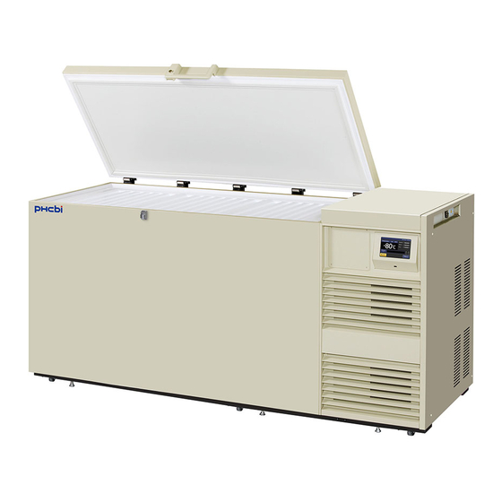
FREEZER COMPONENTS Unit The model below is the MDF-DC700VX. However, the MDF-DC500VX is also equivalent structures. Right side Handle 14 15* 16* Side table (3 pieces) Back side Caster (3 pieces (6 pieces) on the front side) - Page 11 FREEZER COMPONENTS 1. Keyhole: Turn clockwise to 180 with a key and the outer door is securely locked. 2. Door: Hinged type. The door can be opened in any angle on the way to full open. 3. Magnetic door gasket: Seals the door and prevents leakage of cold air. 4.
-
Page 12: Lcd Touch Panel
LCD touch panel The following display (called the Top screen) will appear when the power switch is turned ON. Note: It takes approximately 20 seconds until Top screen is displayed. 1. Present temperature display field: The current chamber temperature is displayed. Note: An integer rounded off below a decimal point is displayed. - Page 13 FREEZER COMPONENTS 8. Message display field: The information of the operation monitor system, alarms or errors are displayed when fault occurs. Refer to page 45~47. 9. Message select key: When there are a number of alarm, errors or information of the operation monitor system, the message on the screen is changeable.
-
Page 14: Remote Alarm Terminal
Remote alarm terminal The alarm of this unit can be informed at a remote location from this unit by connecting the external alarm device to the remote alarm terminals. For the type and behavior of remote alarm output, refer to page 46 ~47. -
Page 15: Installation Installation Site
INSTALLATION Installation site To operate this unit properly and to obtain maximum performance, install the unit in a location with the following conditions: ■ A location not subjected to direct sunlight Do not install the unit under direct sunlight. Installation in a location subjected to direct sunlight cannot obtain the intended performance. -
Page 16: Installation
■ A location without corrosive substance Never install the unit in a location where corrosive substance such as sulfur-contained compound may generate (ex. near a sink). The corrosion of copper pipe of the cooling circuit may result in the failure of the unit. -
Page 17: Start-Up Of Unit
START-UP OF UNIT Follow the procedures for the initial and consequent operations of the unit. 1. Make sure that both of the power switch and the battery switch for power failure alarm are OFF (factory setting is OFF). Note: When the power switch is ON and the battery switch for power failure alarm is ON, the power failure alarm is activated (refer to page 46). -
Page 18: Operation During Power Failure
Operation during power failure When the battery switch for power failure is ON, during a power failure the behavior of this unit is as follows. ●The power failure alarm is activated (refer to page 46). Press Buzzer key to silence the buzzer of the power failure alarm. In case the ring back is turned ON, buzzer sounds again when a power failure still continues after ring back set time passed (refer to page 28). -
Page 19: Basic Operation On Lcd Touch Panel
BASIC OPERATION ON LCD TOUCH PANEL ◆Message select key: (Operate) Changing some messages ◆Buzzer key: (Operate) Silencing the buzzer (Alarm is not canceled except for some alarms; page 48) ●Operation from Menu key ■Menu screen Page ◆Set → ■Temp. Setting screen 21~22 (Setting) Temp., High Alarm, Low Alarm ◆Log... -
Page 20: Basic Parameters
BASIC PARAMETERS How to input numerical value and alphanumeric character On each screen in the LCD touch panel, it may be necessary to input numerical value or alphanumeric characters. ●When inputting numerical value Numeric input box 1. By pressing numeric input box, numeric input window is displayed. - Page 21 BASIC PARAMETERS Alphanumeric input box ●When inputting alphanumeric characters pressing alphanumeric input box, alphanumeric input window is displayed. Alphanumeric input window 2. Press alphabetic key and numeric key to input alphanumeric characters, and press OK key. 仮 ●Key description ・Alphabetic key (A~Z, Space): Input alphabetic characters or spaces. ・Numeric key (0~9): Input numerical values.
-
Page 22: Setting Temperature, High Alarm And Low Alarm
Setting Temperature, High Alarm and Low Alarm Set the Temperature, High Alarm and Low Alarm for normal operation according to the following procedure. The unit automatically starts operation using these settings after power-on. 1. Press Menu key to lead the Menu screen. 2. -
Page 23: Setting Operation Control Mode
BASIC PARAMETERS * The current chamber temperature is the value rounded off below a decimal point, so the High/Low Alarm may be activated when the value of the current chamber temperature is equal to the High/Low Alarm set temperature. 4. On the Menu screen, press Back key to return to the Top screen. Setting operation control mode 1. - Page 24 4. Input each parameter. Press Apply key to save the input value and setup. The display returns to the Tools screen. ●Each setting ・Control: Choose the operation control mode between the NORMAL (normal control) or the ECO (eco control). By holding the Control slide key and sliding it right, operation control mode is changed to ECO.
-
Page 25: Setting Key Lock
BASIC PARAMETERS Setting key lock 1. Press Menu key to lead the Menu screen. 2. Press Key Lock key to lead the Key Lock screen. 3. On the Key Lock screen, it is possible to set each setting of key lock (refer to next page). Press Apply key to change key lock ON and to save the password. - Page 26 ●Each setting of key lock ・Key Lock: By holding Key Lock slide key and sliding it to the right, Key Lock turns to ON. ・Password: The number (Max. 6 digits) inputted here are registered the release password of Key Lock. ・Confirm Password: To prevent erroneous input, input the same password as Password input box.
-
Page 27: Removing Key Lock
BASIC PARAMETERS Removing key lock 1. By pressing Menu key, the Password input window is displayed. 2. On Password input box, input the set release password of Key Lock, and press OK key to lead the Menu screen. 3. Press Key Lock key to lead the Key Lock screen. -
Page 28: Alarm Parameters
ALARM PARAMETERS 1. Press Menu key to lead the Menu screen. 2. Press Tools key to lead the Tools screen. 3. Press Alarm Setting key to lead the Alarm Setting screen. - Page 29 ALARM PARAMETERS 4. On the Alarm Setting screen, it is possible to set each setting. Press Apply key to save the input value and setup. The display returns to the Tools screen. ●Each setting ・Alarm Delay: The function is that when the unit is in the alarm state of High Alarm or Low Alarm, the alarm buzzer will sound after the alarm delay set time passed.
- Page 30 ● At the alarm state ・While the unit’s alarm is being activated and the buzzer is being sounding, the buzzer is silenced by pressing Buzzer key. For the behavior at the time of pressing Buzzer key and the re-activation of alarm, under each setting condition, refer to Table 4-5 on page 48.
-
Page 31: Operation/Alarm Log Setting Log Interval
OPERATION/ALARM LOG Setting log interval The unit is equipped with a function of saving operation log data (chamber temperature and open/close state of door). Note: When the battery switch for power failure alarm is ON, operation log is saved during a power failure. -
Page 32: Displaying Operation Log
4. On the Setting screen, input Log Interval. Press Apply key to save the input value. The display returns to the Log screen. Settable range: 2 minutes~30 minutes. Factory setting: 6 minutes. Note: Only an even number can be inputted. When inputting an odd number and when pressing OK key in the numeric input window, it changes to an even number which is 1 smaller than that. - Page 33 OPERATION/ALARM LOG 3. Press Chart key to lead the Chart screen. 4. On the Chart screen, input the date (year / month / day) of the operation log you want to display graphically. 5. On the Chart screen, by pressing Show key after pressing the item you want to display graphically, the graph of each operation log is displayed.
- Page 34 Export key* To previous day To next day 6. Actual Temp. log graph is displayed. ・Press Back key to return to the Chart screen. ・Press Top key to return to the Top screen. To Door Opening log To Actual Temp. log To previous day Export key* 7.
-
Page 35: Exporting Operation Log
OPERATION/ALARM LOG Exporting operation log Operation log data saved in the freezer can be exported in CSV format to the USB memory inserted into the USB port. 1. Insert the USB memory into the USB port. Note: It is not possible to use a USB memory with security functions that requires entering password. 2. - Page 36 5. On the Export screen, select the time period you want to export. ・To export the saved operation log data over the entire period, press All radio button. ・To export the operation log data of a specified date, press 1 Day radio button and input the date (year / month / day) of the operation log data you want to export.
- Page 37 OPERATION/ALARM LOG Note: When the specified operation log data does not exist, Notice dialog box is displayed. Press OK key, and then re-specified according to procedure 4 and 5. 7. When the export is complete, Information dialog box is displayed. Press OK key. Note: Even after the export of operation log data is complete, operation log data saved in the unit are not deleted.
-
Page 38: Displaying Alarm Log
Displaying alarm log The unit is equipped with a function of saving alarm log data (Max. 256 logs). Note: ・When saving alarm logs more than 257, the oldest alarm log is deleted, and then overwritten. ・When the battery switch for power failure alarm is ON, operation log is saved during a power failure. Alarm log saved in the freezer can be displayed graphically on the LCD touch panel. - Page 39 OPERATION/ALARM LOG 4. On the Alarm screen, the newest 7 days’ alarm logs (containing that day) are displayed. Note: When the number of applicable alarm log is 6 or more, by pressing the top (▲) or the bottom (▼) log, the log table currently displayed scrolls and hidden alarm logs can be seen.
-
Page 40: Exporting Alarm Log
Exporting alarm log It is possible to export saved alarm log data to a USB memory inserted in the USB port by CSV format. 1. Insert a USB memory in the USB port. Note: It is not possible to use a USB memory with security functions that requires entering password. 2. - Page 41 OPERATION/ALARM LOG 5. On the Alarm Export screen, select the period to export. ・To export the saved alarm log data over the entire period, press All radio button. ・To export the alarm log data for the specified days (The newest period containing that day), press Last XX Days radio button and input days.
- Page 42 7. Even after completion the export of alarm log data, Information dialog box is displayed. Press OK key. Note: After completing the export of alarm log data, alarm log data saved at unit is not deleted. 8. Remove a USB memory from the USB port. Note: A log folder is created in a USB memory, and an exported data file is saved in the log folder by CSV format.
-
Page 43: Other Parameters
OTHER PARAMETERS Setting date and time 1. Press Menu key to lead the Menu screen. 2. Press Tools key to lead the Tools screen. 3. Press Date & Time key to lead the Date & Time screen. 4. On the Date & Time screen, input the present date and time. -
Page 44: Setting Brightness And Sleep
Setting brightness and sleep 1. Press Menu key to lead the Menu screen. 2. Press Tools key to lead the Tools screen. 3. Press Brightness/Sleep key to lead the Brightness/Sleep screen. 4. On the Brightness/Sleep screen, each setting of brightness and sleep is available. Press Apply key to save the input value and setup. - Page 45 OTHER PARAMETERS ●Each setting ・Brightness(Active): Brightness of LCD touch panel of the usual state. Adjust Brightness(Active) slide bar or input set value into the Brightness(Active) input box. Settable range: 50~80, factory setting: 80. ・Sleep: The function is that the rightness of LCD touch panel is lowered to save electricity, when there is no key operation during set time.
-
Page 46: Operation Monitor System
OPERATION MONITOR SYSTEM This unit has the operation monitor system. It is the function to detect and inform some hard operating conditions that leaving the unit operating may cause a failure. The table 2 shows the information of the operation monitor system. Table 2 Information of the operation monitor system Message If this status... -
Page 47: Alarms, Safety, And Self-Diagnosis
ALARMS, SAFETY, AND SELF-DIAGNOSIS This unit has the alarms, safety functions, and self-diagnostic functions of the table 3. Table 3 Alarms and safety function list LCD touch panel Remote Alarm & safety Situation Buzzer Message alarm Other display field ・Alarm display If the chamber temperature exceeds Warning: (During alarm delay) - Page 48 Table 3 Alarms & safety function list LCD touch panel Remote Safety Alarm & safety Situation Buzzer alarm operation Message display field Alarm display “Warning” is displayed If the thermal sensor is Err01: alternately in Unit is disconnected. Temperature Sensor Open. normal Intermittent continuous...
- Page 49 ALARMS, SAFETY, AND SELF-DIAGNOSIS ●Table 4~5 show the behavior of the alarm (buzzer) and Ring Back function when pressing Buzzer key. Table 4 In the cases of other than the door alarm. Buzzer from unit Remote Alarm Ring Back Remote Alarm setting When pressing When the Ring Back When pressing...
-
Page 50: Routine Maintenance
ROUTINE MAINTENANCE WARNING Always disconnect the power supply to the unit prior to any repair or maintenance of the unit in order to prevent electric shock or injury. Ensure you do not inhale or consume medication or aerosols from around the unit at the time of maintenance. -
Page 51: Defrosting Of Chamber
ROUTINE MAINTENANCE Defrosting of chamber After long term use of this unit, the frost is built on the inside wall of the chamber and inner lid. The excessive frost possibly make some gap between the cabinet and door gasket, which may cause poor cooling. -
Page 52: Replacement Of Wear-Out Parts
REPLACEMENT OF WEAR-OUT PARTS Replacing the battery for power failure alarm Replace the battery for power failure alarm every 3 years. Contact our sales representative or agent for the replacement of battery when “Warning: Exchange a Main Battery.” is displayed in the message display field. -
Page 53: Troubleshooting
TROUBLESHOOTING If the unit malfunctions, check out the following before calling for service. Malfunction Check/Remedy ■ The unit is not connected to the power supply. The unit does not operate ■ During a power failure. at all when turning ON the ■... -
Page 54: Disposal Of Unit
DISPOSAL OF UNIT Before disposing the unit with biohazardous danger, decontaminate the unit to the extent possible by the user. WARNING If the unit is to be stored unused in an unsupervised area for an extended period ensure that children do not have access and doors cannot be closed completely. - Page 55 The symbol mark and recycling systems described below apply to EU countries and do not apply to countries in other areas of the world. Your Panasonic product is designed and manufactured with high quality materials and components which can be recycled and/or reused.
- Page 56 POUR LES UTILISATEURS DE UE Le symbole et les systèmes de recyclage évoqués ci-dessous s'appliquent uniquement aux pays de UE. Votre produit Panasonic est conçu et fabriqué avec des composants et des matériaux de hautes qualités qui peuvent être recyclés et/ou réutilisés.
- Page 57 O símbolo e os sistemas de reciclagem descritos abaixo aplicam-se aos países da UE e não se aplicam aos países noutras áreas do mundo. O seu produto Panasonic foi concebido e fabricado com materiais e componentes de elevada qualidade que podem ser reciclados e/ou reutilizados.
- Page 58 Den symbolmärkning och de återvinningssystem som beskrivs här nedan gäller länder inom EU och gäller inte länder i någon annan del av världen. Din Panasonic -produkt har konstruerats och tillverkats med delar och material av hög kvalitet, som kan återvinnas och/eller återanvändas.
-
Page 59: Temperature Recorder (Option)
TEMPERATURE RECORDER (OPTION) The chamber temperature can be recorded and checked by installing an optional temperature recorder MTR-85H or MTR-G85C. Contact our sales representative or agent for the purchase of temperature recorder. Main specifications of temperature recorder MTR-85H MTR-G85C Recording -100 C~+50 -100... -
Page 60: Backup Cooling Kit (Option)
BACKUP COOLING KIT (OPTION) By installing an optional backup cooling kit MDF-UB5 and a liquid CO cylinder, liquid CO injection into the chamber prevent to rise the chamber temperature for a few hours, even when this unit stops operation by a power failure and so on. Contact our sales representative or agent for the purchase of backup cooling kit. -
Page 61: Specifications
SPECIFICATIONS Ultra-Low Temperature Freezer Ultra-Low Temperature Freezer Product name MDF-DC500VX MDF-DC700VX Storage of cells, organs, DNAs, plasma. Medical purpose W2010 mm x D845 mm x H1070 mm W2300 mm x D845 mm x H1070 mm External dimensions W1190 mm x D640 mm x H756 mm W1480 mm x D640 mm x H756 mm Internal dimensions 575 L... -
Page 62: Performance
PERFORMANCE Ultra-Low Temperature Freezer Ultra-Low Temperature Freezer Product name MDF-DC500VX MDF-DC700VX MDF-DC500VX-PE MDF-DC700VX-PE Model number C at the center of the chamber (ambient temperature; 30 C, no load)* Cooling performance Temperature settable range C to -90 C to -86 C (ambient temperature; 30 C, no load) Temperature control range AC 230 V/240 V... -
Page 63: Safety Check Sheet
CAUTION Please fill in this form before servicing. Hand over this form to the service engineer to keep for his and your safety. Safety check sheet 1. Freezer contents : Risk of infection: □Yes □No Risk of toxicity: □Yes □No Risk from radioactive sources: □Yes □No... - Page 64 Original Operating instructions < EU countries only > 0123 Panasonic Marketing Europe GmbH Panasonic Testing Centre Winsbergring 15, 22525 Hamburg, Germany Printed in Japan 1-1-1 Sakata, Oizumi-Machi, Ora-Gun, Gunma 370-0596, Japan LDCL000600-1 S0615-10116 © Panasonic Healthcare Co., Ltd. 2015 2016.01.08...
Need help?
Do you have a question about the MDF-DC700VX Series and is the answer not in the manual?
Questions and answers