Rane AC 22B Operator's Manual
Active crossover
Hide thumbs
Also See for AC 22B:
- Operating & service manual (5 pages) ,
- Datasheet (4 pages) ,
- Operator's manual (12 pages)
Advertisement
Quick Links
QUICK START
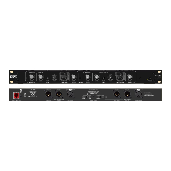
The AC 22B can be either a Stereo 2-Way or Mono 3-Way crossover. Labels above the controls refer to the unit being
operated in the 2-Way Stereo mode. Labels below the controls refer to the unit being operated in the 3-Way Mono mode.
The AC 22B is a fully balanced output version of the popular AC 22 and is equipped with 3-pin (XLR type) conectors
instead of the standard ¼" TRS jacks. All other features, specifications and operation are identical with the standard
model with an added switch. Where the AC 22 is configured somewhat automatically by using switching jacks, the AC
22B is configured by a SYSTEM MODE switch added to the back of the unit.
To operate the AC 22B in Stereo 2-Way mode, be sure that the Mode switch is set for STEREO 2-WAY. Follow the
labels above the controls and jacks.
When operated in the Mono 3-Way mode, the switch should be set in the MONO 3-WAY position. Follow the labels
below the controls and jacks. In Mono 3-Way mode the Channel 1 High Output is unusable. This output is the high-pass-
only portion of the midrange filter. The Channel 1 High Level and the Channel 2 Master Level are also defeated on the
front panel.
NEVER CONNECT ANYTHING EXCEPT AN RS 1 OR OTHER APPROVED RANE AC POWER SUPPLY
TO THE THING THAT LOOKS LIKE A TELEPHONE JACK ON THE REAR. This is an AC supply and requires
some special attention if you do not have an operational power supply EXACTLY like the one that was originally
packed with your unit.
AC 22B CONNECTION
In agreement with IEC and AES/ANSI standards, AC 23B
wiring convention is pin 2 Positive, pin 3 Negative (return),
pin 1 Signal ground (for unbalanced use), with the connector
case or shell tied to chassis ground.
BALANCED OPERATION
Use only when driving from a true balanced source and
driving to a true balanced destination—either transformer
coupled or active drive. Connect the input to pins 2 and 3
with pin 2 positive. Do not connect pin 1. Terminate the
shield to the case or shell. Connect the output to pins 2 and 3
with pin 2 positive. Do not connect pin 1. Connect the shield
to the case or shell.
OPERATORS MANUAL
ACTIVE CROSSOVER
UNBALANCED OPERATION
Connect the input between pins 2 and 1 with pin 2 positive
and pin 1 Signal ground. Short pin 3 to pin 1. Terminate the
shield to the case or shell. Connect the output between pins 2
and 1 with pin 2 Positive. Leave pin 3 open—do not short it
to pin 1. Connect the shield to the case or shell.
COMBINATION OPERATION
For combined balanced and unbalanced operation, use
whichever half of the above instructions apply for each end.
See the "Sound System Interconnection" RaneNote
included in this manual for more information on cabling and
grounding requirements.
AC 22B
Manual-1
Advertisement

Related Manuals for Rane AC 22B


Summary of Contents for Rane AC 22B
-
Page 1: Quick Start
QUICK START The AC 22B can be either a Stereo 2-Way or Mono 3-Way crossover. Labels above the controls refer to the unit being operated in the 2-Way Stereo mode. Labels below the controls refer to the unit being operated in the 3-Way Mono mode. - Page 2 FRONT PANEL: STEREO 2-WAY CONFIGURATION Observe the labels screened above the controls for stereo operation. 1. POWER switch: Self-evident. 2. POWER indicator: When this yellow LED is lit the unit is ready to operate. 3. CHANNEL 1 MASTER LEVEL: This controls the overall Level of Channel 1 without altering the relative settings of the HIGH and LOW Outputs.
- Page 3 6. SYSTEM MODE switch: Set this switch for STEREO 2-WAY operation. 7. POWER input connector: Use only an RS 1, or other remote AC power supply approved by Rane. This unit is supplied with a remote power supply for connection to this input jack. Consult the factory for replacement or substitution. This unit’s power input is designed for an AC supply, delivering 18-24 volts, from a center-tapped transformer capable of supplying at least the current demanded by this product.
- Page 4 FRONT PANEL: MONO 3-WAY CONFIGURATION Observe the labels below the controls for Mono operation. 1. POWER switch: Self-evident. 2. POWER indicator: When this yellow LED is lit, the unit is ready to operate. 3. CHANNEL 1 MASTER LEVEL: This controls the overall Level without altering the relative settings of the HIGH, MID and LOW Outputs.
- Page 5 6. SYSTEM MODE switch: Set this switch for MONO 3-WAY operation. 7. POWER input connector: Use only an RS 1, or other remote AC power supply approved by Rane. This unit is supplied with a remote power supply suitable for connection to this input jack. Consult the factory for replacement or substitution.
- Page 6 Chances are that even careful visual alignment on these will often yield a Fre- quency error greater than a full detent on the AC 22B. 3. If it is absolutely critical to obtain the exact Crossover Frequency (Mil Spec., P.A., etc.), the selector can be...
- Page 7 (see Figure 1). This gets hard to put up with, time Delay. Some references will be made to Rane RA 27 because the end result is that your speaker system will have...
- Page 8 STEP BY STEP PROCEDURE as the Rane AD 22B. The built-in Delay system in the A 3-Way mode consisting of high, mid and low drivers is AC 22B is designed to accommodate the majority of used here as an example.
- Page 9 The built-in Delay system in the AC 22B is designed to accommodate the majority of common speaker configurations; if you encounter confusion or difficulty with your particular system, it is best to consult your dealer or the Rane factory for assistance.
- Page 10 In order to phase-align two drivers you must observe only Delay vs. Frequency Table the crossover frequency, which is common to both drivers. If you do not have the equipment necessary to electroni- Pink noise can be used if all other frequencies are disre- cally align the system as described in the previous sections, garded, since room acoustics and imperfect driver response you may use the table below to obtain a rough and approxi-...
-
Page 11: Channel Two
Time Delay Transplant Modification CHANNEL TWO: 1. Refer to the board layout diagram. We have added modification jumpers to the AC 22B. 2. On the board layout locate W43 near Z203 and W45 These jumpers permit the transplanting of the Delay circuits behind the CH 2 Delay pot. - Page 12 6. Adjust the display controls on the analyzer so that it shows The Fix-lt-With-The-Crossover School. Here the the greatest number of 0 dB LED’s (green on Rane crossover knobs get a good workout, for the crossover is used equipment) below the crossover frequency.
- Page 13 Pink Noise Generator over, and check that noise is emitting from all the speaker The MUTE switches on the AC 22B make using an SPL components. The crossover should now be aligned. Make meter an easy and relatively accurate means of tuning a any overall level adjustments with the MASTER LEVEL system.
-
Page 14: Important Note
.0018 µf 4.0 kHz .0015 µf 5.0 kHz .0012 µf 6.0 kHz .001 µf ©Rane Corporation 10802 47th Ave. W., Mukilteo WA 98275-5098 TEL (425)-355-6000 FAX (425)-347-7757 WEB http://www.rane.com All features & specifications subject to change without notice. 520-438 SEP96 Manual-14...
Need help?
Do you have a question about the AC 22B and is the answer not in the manual?
Questions and answers