Advertisement
Advertisement
Table of Contents

Related Manuals for Peak FCB4N2


Summary of Contents for Peak FCB4N2
- Page 1 P P P P E E E E A A A A K K K K MIDI SWITCHING PRODUCTS FCB4N2 PROGRAMMABLE MIDI FOOT CONTROLLER OWNER’S MANUAL Document Rev.2.1.0 Feb.11.2010 www.peak2005.com...
-
Page 2: Table Of Contents
PEAK FCB4N2-Programmable MIDI foot controller Table of contents INTRODUCTION ……..…………………………………………………………………..………………..3 … Overview …………………………..…………… …………………………………………..…..3 TOP Panel ……………………………………………………………………………………….……….3 BACK Panel ………………………………………………………………………………………..4 Specification ……………………………………………….…………………………………………...4 Power connection ….……………………………………………..……………………………..5 BASIC OPERATION ………………………………………………………………………………………..6 Bank and Preset selection …………………………………..……………………………………..6 SETUP MODE AND PRESET PROGRAMMING ………………………………………………………….6 Programming Mode Entry …..……………………………………………………………………..6 Factory Restore ..………………………………………………………………………………………9... -
Page 3: Introduction
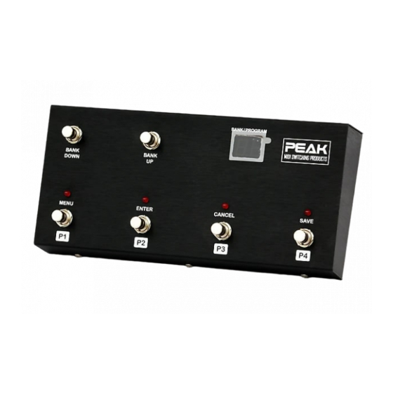
MIDI channels). The FCB4N2 has up/down bank and 4 patch selection buttons, all with high quality heavy duty foot switches that you can feel when pressed. The chassis is made of aluminum, folded by a laser cutting process and finished with a black anodized coating. -
Page 4: Back Panel
PEAK FCB4N2-Programmable MIDI foot controller Back Panel. MIDI OUT: The MIDI out port is used to transmit MIDI messages from the unit to other MIDI device/s. It is an 8 pin MIDI connector so you can supply phantom power to the unit by supply voltage between 9V – 12V to pin 6, 7 (AC or DC, it does not matter) and pin 8 is not used. -
Page 5: Power Connection
Power Connection. The FCB4N2 has flexible power requirements between 9V-12V, AC or DC, 200mA. If you are using a POD 2.0 (or XT), you can plug the 9VAC power supply to an IO port (select one) and then link the power supply to your POD 2.0 (or XT) unit via the other port. -
Page 6: Basic Operation
BASIC OPERATION Please refer to the text that appears under the switches when you are going to use the FCB4N2 unit in the basic operation mode. On power up, the latest preset will be selected and transmitted as a MIDI message via MIDI out (Initial value is Bank#1, preset#1). - Page 7 PEAK FCB4N2-Programmable MIDI foot controller Press bank up / down for select setting PC1: MIDI Channel PC1: PC# PC2: MIDI Channel PC2: PC# PC3: MIDI Channel PC3: PC# PC4: MIDI Channel PC4: PC# CC: MIDI Channel C1: Controller# C1: Value...
-
Page 8: Factory Restore
Factory Restore You can reset the FCB4N2 to the factory default settings. The data that you saved in the EEPROM memory will be erased and the unit returned back the factory default settings. You can restore the factory default by following these steps: 1. -
Page 9: Midi Cable Support
MIDI Cable Support The FCB4N2 is a standard MIDI foot controller that you can connect to any MIDI equipment you want via a standard 5 pin MIDI cable. If you want to supply phantom power into the FCB4N2 unit, it is available by using a 7 pin midi cable with pins 6 and 7 used for the power supply.
Need help?
Do you have a question about the FCB4N2 and is the answer not in the manual?
Questions and answers