Table of Contents
Advertisement
Advertisement
Table of Contents

Related Manuals for XTA dp200


Summary of Contents for XTA dp200
-
Page 3: Table Of Contents
Contents Safety Warnings .........................5 Unpacking the DP200.........................5 Introduction ..........................6 Front Panel Functions ........................8 Rear Panel Functions .........................9 Operating The DP200.......................10 DP200 Configurations ......................12 Parametric Equaliser modes ....................12 Parametric Equalisation Block diagrams ................13 Parametric Equalisation and Limit Modes................14 Crossover modes ........................16 Crossover Block diagrams ....................17... -
Page 5: Safety Warnings
Thanks Thank you for choosing the XTA DP200 for your application. Please spare a little time to digest the contents of this manual, so that you obtain the best possible performance from this unit. All XTA products are carefully engineered for world class performance and reliability. -
Page 6: Introduction
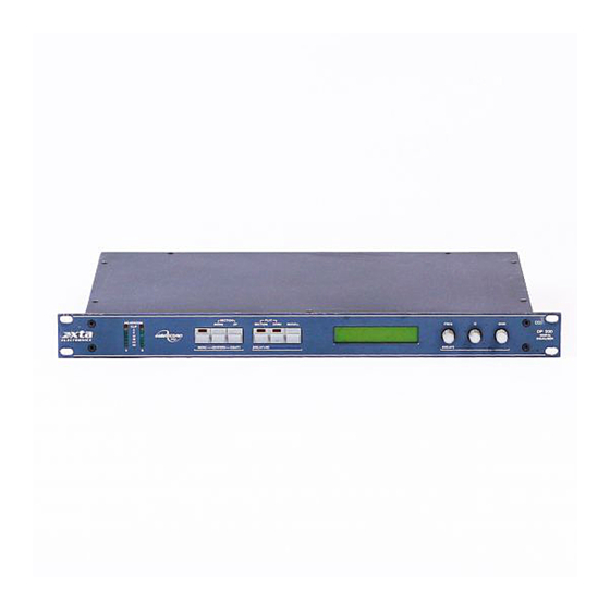
Introduction The DP200 is a compact and powerful DSP based audio processing unit, ideally suited for fixed installations, where it combines the functions of multiple conventional products in a compact 1U high unit. To achieve this the DP200 provides:- 2 input 4 output format, 10 configurations including 4 crossover modes, 4 x 8 bands of parametric equalisation, up to 682mS delay, variable High and Lowpass filters, 4 output limiters and digital level controls for each output. - Page 7 & linking master / slave units, selectable operating level and multi-level security lock-out function. • The DP200 provides exceptional audio quality with a full 103dB dynamic range, high sampling rate and minimal filtering. • Wide range digital control of level is provided for each output. This also allows mute to be applied to any output.
-
Page 8: Front Panel Functions
7. Scroll Key - Scrolls the screen through the available channels for the current configuration. 8. LCD Display - Shows menu options, output information and various parameters dependant on the menu selection. 9. Parameter Controls - The three rotary encoders allows the relevant parameter to be adjusted. DP200 Page 8... -
Page 9: Rear Panel Functions
1 and 2 via output 1's XLR connector, if the AES/EBU option is fitted. 8. Digital Input Switch - pressing this recessed switch will change XLR Input A to a 2 channel AES digital format input, if the AES/EBU option is fitted. DP200 Page 9... -
Page 10: Operating The Dp200
Operating the DP200 AudioCore Windows™ Operations The following operating information covers control of the DP200 via front panel controls only. Please see additional information despatched with AudioCore software and interface options if computer control is required. Preliminary Set-up The following procedure should be followed when first installing the DP200. - Page 11 ‘Supervisor’ to lock all main system functions e.g. configuration, crossover slopes and output E.Q., but leaving the ‘User’ access to input delay and E.Q. etc. The ‘User’ can in turn lock some or all of the functions that he has access to. DP200 Page 11...
-
Page 12: Dp200 Configurations
DP200 Configurations Introduction To simplify set-up of the DP200, 10 configurations are menu selectable. These fall into three main groups:- Parametric equalisers, Parametric equalisers with limiters and Crossover modes. For detailed information on theses modes please study the block diagrams along with the following descriptions. Within each group, stereo modes are available to provide precise 'ganged' parameter adjustment for stereo sources. -
Page 13: Parametric Equalisation Block Diagrams
Figure 2 (Dual 16 Band) - 2 Input, 2 Output, 16 Band Parametric INPUT A OUTPUT 3 INPUT B OUTPUT 1 OUTPUT 2 OUTPUT 4 GAIN DELAY Figure 3 (Stereo 16 Band) - 2 Input, 2 Output, 16 Band Parametric DP200 Page 13... -
Page 14: Parametric Equalisation And Limit Modes
30dB. Parametric filters are carefully implemented using Double Precision processing. This method is costly in terms of processing power but yields substantial benefits in terms of the DP200's exceptional noise performance and greatly improved low frequency stability. Output Limiters High performance digital limiters are provided for each output with control over attack time, release time and threshold level parameters ( see page 22 ). - Page 15 Figure 5 (Dual 14 Band + Limit) - 2 Input, 2 Output, 14 Band Parametric + Limiters INPUT A OUTPUT 3 INPUT B OUTPUT 1 OUTPUT 2 OUTPUT 4 GAIN LIMIT DELAY Figure 6 (Stereo 14 Band + Limit) - 2 Input, 2 Output, 14 Band Parametric +Limiters DP200 Page 15...
-
Page 16: Crossover Modes
It should also be noted that the turnover frequency displayed on the DP200 is the -3dB point for all slopes except 24dB Linkwitz-Riley where the -6dB point is shown. If the -6dB... -
Page 17: Crossover Block Diagrams
GAIN DELAY DELAY GAIN LIMIT OUTPUT 3 LO MID DELAY GAIN LIMIT OUTPUT 2 HI MID DELAY GAIN LIMIT OUTPUT 4 DELAY GAIN LIMIT Figure 9 (4 way Crossover) - 4 way Crossover with Limiters and Delay DP200 Page 17... -
Page 18: Input Level
In addition a powerful 6 band parametric equaliser is provided on each input. This allows full room equalisation to be performed using the DP200 saving the cost, space and wiring requirements of external units. -
Page 19: Gain, Delay And Phase Function Screen
+15dB to -40dB and mute for an output channel, 0dB to -40dB for input channels. With an output channel selected for adjustment, pressing the [Delay *10] key shows the phase, the gain control can then be used to switch the phase. DP200 Page 19... -
Page 20: High And Lowpass Filters Function Screen
(highpass greater than lowpass), attempting to do so will cause the unit to flash the message 'High / Low Conflict'. 10. Q Control - Adjusts the filter type (see 8). DP200 Page 20... -
Page 21: Parametric Equalisation Function Screen
PEQ numbers 1 and 2, which can be switched into Low and High shelf modes respectively; the mode. 10. Gain - Shows the gain of the current filter. 11. Frequency Control - Adjusts the centre frequency of the filter in 1/24 octave steps. DP200 Page 21... -
Page 22: Limiter Control Function Screen
9. Rel - Shows the limiter release time as Fast, Medium or Slow. In the Fast setting the release time will be 4 times the Attack time. For Medium and Slow it will be 8 and 16 times respectively. DP200 Page 22... -
Page 23: Limiter View Function Screen
Split 3 + 1 way crossover (1+ 2 + 3) (1 + 2 + 3 + 4) Note: When ‘Limiter Link’ function is selected, limiters will operate on all linked outputs even where ‘Limiter bypass’ is selected for that output. DP200 Page 23... -
Page 24: Memory Store
Only memory numbers containing stored information will be displayed. Frequency Control - used to select required memory. [Enter] key - Press this key to recall the memory number shown on the display. DP200 Page 24... -
Page 25: Security System
Note 2: If the security code number is inadvertently lost contact your local XTA sales office. MIDI Operation The DP200 is supplied with a MIDI interface as standard. The unit can be placed in Off, Master and Slave modes. In 'Slave' mode the DP200 will monitor MIDI messages on the MIDI input connector... -
Page 26: Rs232, Rs422 And Rs485 Operation
In 'Slave' mode the DP200 will monitor messages from either AudioCore software or another DP200 (set in 'Master' mode). In 'Master' mode the DP200 will send a memory recall command when a memory is recalled. Press 'MENU' and select Interface Set-up using menu / scroll keys or parameter control. -
Page 27: Aes/Ebu Units
AES/EBU; Inputs A and B are provided on Input A connector, Outputs 1 and 2 on Output 1 connector and Outputs 3 and 4 on Output 3 connector. Menu Selections With the AES/EBU option fitted, AES Receive and Diagnostic modes are provided. AES Receive Mode: DP200 Page 27... - Page 28 4. Reference - Input is selected to analogue, but the external AES signal is used to control the sample rate of the DP200. In this way the AES/EBU outputs are referenced-locked to the incoming AES clock.
-
Page 29: Equalisation Curves
Equalisation Curves Figure 10 - Parametric filter gain curves. Figure 11 - Parametric filter 'Q' curves. Figure 12 - Parametric filter High and Low shelf curves. DP200 Page 29... - Page 30 Figure 13 - Highpass filter curves. Figure 14 - Lowpass filter curves. Figure 15 - Parametric filter with high 'Q' to achieve notch response. DP200 Page 30...
-
Page 31: Specifications
(8way RJ45 x 2). These options also provide closed- contact memory recall via 8 pin DIN socket. Options = Transformers available. Relay bypass. Digital I/O. Due to continuing product improvement the above specifications are subject to change. DP200 Page 31... -
Page 32: Operating Notes
With any audio signal processing equipment it is necessary to ensure adequate signal level is used through the device, to avoid sacrificing noise performance. The DP200 features a menu selectable choice of operating levels to reduce this problem, (see page 10). It is suggested that the operating level chosen should give adequate level to just light the 6dB LED on the headroom meter with maximum program level being used. -
Page 33: Warranty
During the warranty period, XTA will, at it's option, either repair or replace products which prove to be defective, provided that the product is returned, shipping prepaid, to an authorised XTA service facility.
Need help?
Do you have a question about the dp200 and is the answer not in the manual?
Questions and answers