Table of Contents
Advertisement
Safe Operation Practices • Set-Up • Operation • Maintenance • Service • Troubleshooting • Warranty
O
'
M
peratOr
s
anual
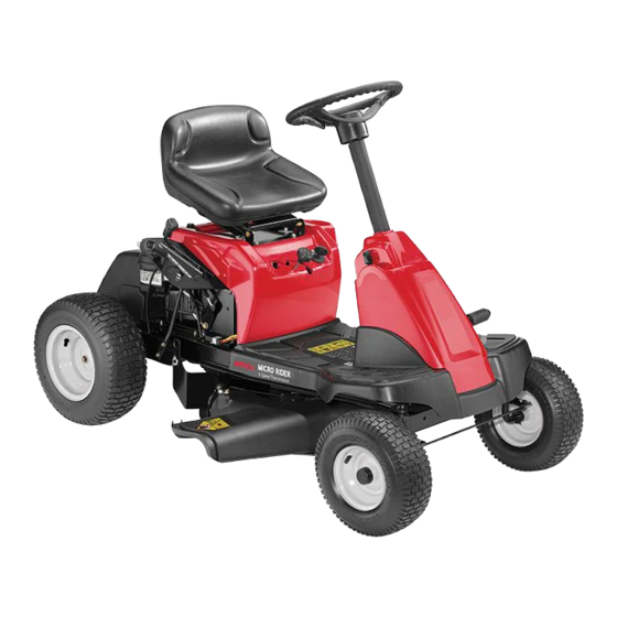
Mini-Rider with 24-inch Cutting Deck
WARNING
READ AND FOLLOW ALL SAFETY RULES AND INSTRUCTIONS IN THIS MANUAL
BEFORE ATTEMPTING TO OPERATE THIS MACHINE.
FAILURE TO COMPLY WITH THESE INSTRUCTIONS MAY RESULT IN PERSONAL INJURY.
MTD LLC, P.O. BOX 361131 CLEVELAND, OHIO 44136-0019
Printed In USA
Form No. 769-08407A
(January 16, 2013)
Advertisement
Table of Contents

Related Manuals for MTD Mini-Rider


Summary of Contents for MTD Mini-Rider
- Page 1 READ AND FOLLOW ALL SAFETY RULES AND INSTRUCTIONS IN THIS MANUAL BEFORE ATTEMPTING TO OPERATE THIS MACHINE. FAILURE TO COMPLY WITH THESE INSTRUCTIONS MAY RESULT IN PERSONAL INJURY. MTD LLC, P.O. BOX 361131 CLEVELAND, OHIO 44136-0019 Printed In USA Form No. 769-08407A...
-
Page 2: Table Of Contents
Visit us on the web at www.mtdproducts.com See How-to Maintenance and Parts Installation Videos at www.mtdparts.com/KnowledgeCenter ◊ Call a Customer Support Representative at (800) 800-7310 or (330) 220-4683 ◊ Write us at MTD LLC • P.O. Box 361131 • Cleveland, OH • 44136-0019... -
Page 3: Safe Operation Practices
Important Safe Operation Practices WARNING! This symbol points out important safety instructions which, if not followed, could endanger the personal safety and/or property of yourself and others. Read and follow all instructions in this manual before attempting to operate this machine. Failure to comply with these instructions may result in personal injury. - Page 4 Slope Operation A missing or damaged discharge cover can cause blade contact or thrown object injuries. Slopes are a major factor related to loss of control and tip-over Stop the blade(s) when crossing gravel drives, walks, or accidents which can result in severe injury or death. All slopes roads and while not cutting grass.
- Page 5 Service Children Tragic accidents can occur if the operator is not alert to the Safe Handling of Gasoline: presence of children. Children are often attracted to the machine and the mowing activity. They do not understand To avoid personal injury or property damage use extreme the dangers.
-
Page 6: Spark Arrestor
Tampering with the governor setting can lead to a runaway do not stop within the this time frame, your machine engine and cause it to operate at unsafe speeds. Never tamper should be serviced professionally by an authorized MTD with factory setting of engine governor. Service Dealer. -
Page 7: Safety Symbols
Safety Symbols This page depicts and describes safety symbols that may appear on this product. Read, understand, and follow all instructions on the machine before attempting to assemble and operate. Symbol Description READ THE OPERATOR’S MANUAL(S) Read, understand, and follow all instructions in the manual(s) before attempting to assemble and operate DANGER—... - Page 8 Symbol Description WARNING—GASOLINE IS FLAMMABLE Allow the engine to cool at least two minutes before refueling. WARNING— CARBON MONOXIDE Never run an engine indoors or in a poorly ventilated area. Engine exhaust contains carbon monoxide, an odorless and deadly gas. DANGER—...
- Page 9 2 — i ection mportant peration racticeS...
-
Page 10: Assembly & Set-Up
Assembly & Set-Up Assembly & Set-Up Contents of Crate • One Riding Mower • One Engine Operator’s Manual • One Hardware Pack • One Steering Wheel/Shaft Assembly • One Seat Assembly • One Product Registration Card • One Operator’s Manual •... - Page 11 Slide the Pedestal cap down onto the tractor (1) and slighty Position the seat assembly in place over the holes, as rotate to the right to clip into place. Secure the pedestal shown in Figure 3-5. with the pan head screw (2) previously removed. See Figure 3-3.
- Page 12 Connecting the Battery Cables Tire Pressure WARNING! Equal tire pressure should be CALIFORNIA PROPOSITION 65 WARNING maintained at all times. Never exceed the maximum Battery posts, terminals, and related accessories inflation pressure shown on the sidewall of the tire. contain lead and lead compounds, chemicals known to the State of California to cause cancer and The recommended operating tire pressure is: reproductive harm.
-
Page 13: Controls & Features
Controls & Features Clutch/Brake Pedal Speed Control & Parking Brake Lever Ignition Switch Shift Lever Deck Lift Lever Cup Holder Oil Fill Cap PTO (Blade Engage) Lever Fuel Fill Cap Figure 4-1 Lawn Tractor controls and features are illustrated in Figure 4-1 and described on the following pages. WARNING! Read and follow all safety rules and instructions in this manual, including the entire Operation section, before attempting to operate this machine. - Page 14 Ignition Switch The ignition switch is located below the operator’s seat on the lefthand side of the tractor as seen from the operator’s position. Activate the Ignition Switch to start the engine by inserting the key into the ignition switch and turn clockwise to the START position.
- Page 15 Deck Lift Lever Found on your tractor’s right fender, the deck lift lever is used to change the height of the cutting deck. To use, move the lever to the left, then place in the notch best suited for your application. PTO (Blade Engage) Lever Found on the tractor’s right fender, the PTO (blade engage) lever is used to engage power to the cutting deck.
-
Page 16: Operation
If the interlock system should ever malfunction, do not operate the tractor. Contact an authorized NOTE: Refer to the Assembly & Set-Up section of this manual for MTD service dealer. gasoline and oil fill-up instructions. •... -
Page 17: Stopping The Engine
Stopping the Engine IMPORTANT: When stopping the tractor for any reason while on a grass surface, always: WARNING! If you strike a foreign object, stop the Place the shift lever into neutral. engine, disconnect the spark plug wire(s) and Engage the parking brake, ground against the engine. -
Page 18: Engaging The Blade
Engaging the Blade Engaging the PTO (Blade Engage) transfers power to the cutting deck. To engage the blade, proceed as follows: Grasp the PTO (Blade Engage) lever and pivot it all the way forward into the engaged (ON) position. IMPORTANT: The PTO (Blade Engage) lever must be in the disengaged (OFF) position when starting the engine, when traveling in reverse, and if the operator leaves the seat. -
Page 19: Maintenance & Adjustment
Maintenance & Adjustments Maintenance Steering Rack & Pinion Once per season, or every 25 hours of operation, it will be WARNING: Before performing any maintenance or necessary to lubricate the steering rack and pinion gear located repairs, disengage PTO, move shift lever into neutral under the front of the unit. - Page 20 Muffler Front To Rear It is possible to adjust the pitch of the cutting deck. The front of WARNING! Temperature of muffler and nearby the deck should be between 0” (level) and 1⁄4” lower than the engine areas may exceed 150˚ F (65˚C). Avoid rear of the deck.
- Page 21 Off Season Storage WARNING! Gasoline is a toxic substance. Dispose of gasoline properly. Contact your local authorities Before storing the machine for an extended period: for approved disposal methods. • Refer to the Maintenance Schedule later in this section and perform all items in the Prior to Storing column. •...
-
Page 22: Maintenance Schedule
Maintenance Schedule Before Every Every Every Every Prior Each use 10 Hours 25 Hours 50 Hours 100 Hours to Storing Check Engine Oil Level Check Air Filter for Dirty, Loose or Damaged Parts Clean and Re-oil Air Filter’s Foam Pre-cleaner (if Equipped) Replace Air Filter Element Change Engine Oil... -
Page 23: Service
Service Cutting Deck Removal Remove the remaining bow-tie cotter pins securing the deck to the unit, as shown in Figure 7-3. To remove the cutting deck, proceed as follows: Place the PTO (Blade Engage) lever in the disengaged (OFF) position and engage the parking brake. Lower the deck by moving the deck lift lever into the bottom notch on the right fender. - Page 24 Changing the Deck Belt Idler Pulley NOTE: It is possible to change the deck belt with the cutting Flange Lock Nut deck still installed on the tractor, however it is much easier to remove the deck first, change the deck belt, then reinstall the cutting deck.
-
Page 25: Cutting Blade
Jump Starting WARNING! Never jump start a damaged or frozen battery. Be certain the vehicles do not touch, and ignitions are off. Do not allow cable clamps to touch. Connect positive (+) cable to positive post (+) of your tractor’s discharged battery. Connect the other end of the cable to the (positive +) post of the jumper battery. -
Page 26: Dealer
Using a block of wood or 2 x 4, insert it into the deck Test the blade’s balance using a blade balancer. Grind opening and rotate the blade around until it wedges the metal from the heavy side until it balances evenly. wood between the deck opening and the cutting blade, as NOTE: When replacing the blade, be sure to install the shown in Figure 7-8. -
Page 27: Troubleshooting
Troubleshooting Problem Cause Remedy Engine fails to start 1. PTO/Blade engaged 1. Place blade engage lever in disengaged (OFF) position. 2. Spark plug wire disconnected 2. Connect wire to spark plug. 3. Fuel tank empty, or stale fuel 3. Fill tank with clean, fresh (less than 30 days old) gas. -
Page 28: Replacement Parts
Replacement Parts Component Part Number and Description 954-05001 Drive Belt (Mowing Deck) 918-06032 Deck Spindle 942-0760 Cutting Blade (24”) 725-04903 Battery 625-05002 734-0298 Tire (Front), 13.0 x 5.0-6.00 734-04641 Tire (Rear), 16.0 x 6.50-8.00 Discharge Chute Assembly 731-2477 NOTE: Download a complete Parts Manual free of charge at www.mtdproducts.com or phone (800) 800-7310 to purchase a Parts Manual. -
Page 29: Attachments & Accessories
Attachments & Accessories The following attachments and accessories are compatible for Mini-Rider Lawn Tractors. See the retailer from which you purchased your tractor, an authorized MTD Service Dealer or phone (800) 800-7310 for information regarding price and availability. CAUTION: Lawn Tractors are NOT designed for use with any type of ground-engaging attachments (e.g. tiller The Mini-Rider or plow). -
Page 30: Emissions Statement
MTD Consumer Group Inc’s application for certification. - Page 31 Add-on or modified parts that are not exempted by the Air Resources Board may not be used. The use of any non-exempted add-on or modified parts by the ultimate purchaser will be grounds for disallowing a warranty claims. MTD Consumer Group Inc will not be liable to warrant failures of warranted parts caused by the use of a non-exempted add-on or modified part.
-
Page 32: Warranty
MANUFACTURER’S LIMITED WARRANTY FOR The limited warranty set forth below is given by MTD LLC with Log splitter pumps, valves, and cylinders have a separate respect to new merchandise purchased and used in the United one- year warranty. States and/or its territories and possessions, and by MTD Products...
Need help?
Do you have a question about the Mini-Rider and is the answer not in the manual?
Questions and answers
how to push when will not start
To push an MTD Mini-Rider when it will not start:
1. Place the shift lever in NEUTRAL.
2. Release the clutch-brake pedal fully.
3. Ensure the parking brake is not engaged.
This allows the tractor to roll freely without the engine running.
This answer is automatically generated
Hi I've bought a used minirider 60RDE with no manual and can't seem to find the engine oil capacity. Can you help please? Regards Steve
HVORFOR KAN MAN IKKE FÅ ET ELDIAGRAM MDT 76 SDE
min plænerklipper kan ikke kører i andet hastighed end lav kan ikke skifte hastighed. JEG SØGER ET EL DIAGRAM MTE 76 SDE