Advertisement
Quick Links
Installing a central vacuum system is a straightforward do-it-
yourself project that doesn't require special tools or skills.
Read the instructions thoroughly before you begin. Take your
time and follow the instructions carefully. Make sure you have
chosen the right installation location and that you are not cut-
ting into any hidden electrical wires or plumbing.
This kit contains all the materials required to install the vacu-
um system including the Vaculine fittings. Vaculine fittings
are manufactured to exacting standards to provide positive
seals, easy installation, and superior airflow characteristics.
Recommended Tools
•
1/2" (1.3 cm) Right Angle Heavy Duty Electric Drill
•
Battery Drill
•
2-1/4" to 2-9/16" Self Feed Drill Bit
•
1/4" (6.4 mm) Masonry Drill Bit
•
Common Hacksaw or Small Handsaw with 18 teeth
per inch blade or 2" PVC Pipe Cutter
•
Mitre Box
•
Pocket or Utility Knife
•
Steel Tape Measure
•
Screwdriver (Slot and Phillips)
•
Electrical Tape or Duct Tape
•
Tie Wraps
•
Wire Coat Hanger
•
Hammer and Nail Puller
•
Side Cutters
•
Wire Connectors for #18 (1.00 mm) wire
•
Flashlight
•
Drywall Saw
•
Wire Stripper
•
Crimping Tool
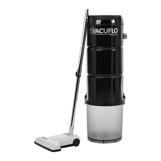
Central Vacuum
System
INSTALLATION MANUAL
Plan Ahead!
Planning is the key to the suc-
cessful installation of a central
vacuum system. Strive to obtain
a balance between the best loca-
tions for the inlet valves and the
practicality of servicing these
locations. Always fully consider
the implications before you cut
into a wall.
Advertisement

Related Manuals for Vacuflo 760 Dual Motor

Summary of Contents for Vacuflo 760 Dual Motor
- Page 1 Central Vacuum System INSTALLATION MANUAL Installing a central vacuum system is a straightforward do-it- Plan Ahead! yourself project that doesn’t require special tools or skills. Read the instructions thoroughly before you begin. Take your Planning is the key to the suc- cessful installation of a central time and follow the instructions carefully.
- Page 2 Planning the Central Vacuum System HOW TO DETERMINE LOCATION FOR POWER UNIT The power unit can be located in the garage, basement, utility room, or any other area that is dry and remote enough that living areas will not be affected by the sound of the electric motor.
- Page 3 Planning the Central Vacuum System (Continued) HOW TO PLAN THE TUBE SYSTEM The amount of airflow that reaches the hose is depend- ent on the efficiency of the tubing system layout. Lines are to be kept as straight as possible. Tight 90-degree fittings are to be used only at inlet valve locations and Multi-Story Houses...
- Page 4 Planning the Central Vacuum System (Continued) HOW TO CUT AND CEMENT PVC TUBING AND FITTINGS Measuring: Measurements should be taken from the molecules from each surface to produce an airtight seal. base of the pipe-stop, which is on the inside of the fit- Before cementing, both the tubing and the fitting must ting hub.
- Page 5 .Electrical Requirements to minimize the length of the exhaust line. Mount the All Vacuflo Power Units are supplied with a power supply unit at a height that will provide convenient access to cord for connection to a grounded receptacle. All wiring the dirt receptacle, or about 6 feet (1.8 m) from the...
- Page 6 How to Install the System (Continued) Step 2 INSTALLATION OF INLET VALVES - EXISTING HOMES (C0NTINUED) Having determined that there are no obstructions in tabs on adapter elbow; then rotate mounting plate into the wall, cut a hole 2 1/4" (57 mm) wide by 3 3/4" (95 an upright position.
- Page 7 How to Install the System (Continued) Step 3 SPECIAL SITUATIONS - EXISTING HOMES Closet Wall Installation of Inlet Valve Floor Installation of Inlet Valve If obstructions make it impossible to run vertical tube While the normal installation of inlet valves is in parti- lines through partition walls, the best and easiest alter- tion walls, occasionally one must be installed in the native is to go through the insides of closets.
- Page 8 How to Install the System (Continued) Helpful Hint Step 4 INSTALLATION OF INLET VALVES - NEW CONSTRUCTION Take measurement from floor to bottom of electrical box. Add 1-7/8” to get Center Point Vertical tube lines and low voltage wiring for inlet of Vac Mounting Plate.
- Page 9 How to Install the System (Continued) Step 5 SPECIAL SITUATIONS - NEW & EXISTING HOMES (CONTINUED) Center VacPan under cabinet so as to avoid standards and cabinet supports. Use a 1x4 and a 2x4 under pipe to get correct height. Dry fit horizontal pipe into sweep 90 that comes up under cabinet.
- Page 10 How to Install the System (Continued) Step 6 COMPLETION OF TUBING SYSTEM (NEW AND EXISTING HOMES) With the inlet valves installed, start at the most distant for dirt to drop into. Always run a branch line out of valve and extend the trunk line toward the power unit. the side or top of the trunk line.
Need help?
Do you have a question about the 760 Dual Motor and is the answer not in the manual?
Questions and answers