Pioneer PD-M427 Service Manual
Multi compact disc player
Hide thumbs
Also See for PD-M427:
- Servise manual (32 pages) ,
- Service manual (32 pages) ,
- Operating instructions manual (40 pages)
Table of Contents
Advertisement
Quick Links
MULTI COMPACT DISC PLAYER
PD-M427
THIS MANUAL IS APPLICABLE TO THE FOLLOWING MODEL(S) AND TYPE(S).
Type
Model
RFXJ
AC110-127V/ 220-240V
PD-M427
For details, refer to "Important symbols for good services" .
PIONEER CORPORATION
PIONEER ELECTRONICS (USA) INC. P.O. Box 1760, Long Beach, CA 90801-1760, U.S.A.
PIONEER EUROPE NV Haven 1087, Keetberglaan 1, 9120 Melsele, Belgium
PIONEER ELECTRONICS ASIACENTRE PTE. LTD. 253 Alexandra Road, #04-01, Singapore 159936
PIONEER CORPORATION 2004
STANDBY/ON
Power Requirement
4-1, Meguro 1-chome, Meguro-ku, Tokyo 153-8654, Japan
MULTI COMPACT DISC PLAYER
DISC
TRACK
MIN
SEC
RANDOM
'
TRACK/MANUAL
EJECT
REPEAT PROGRAM
DISC
STOP PLAY/PAUSE
-DISC
MULTI CD
0
4 1
¡
¢
7
1-BIT•DLC
DIRECT LINEAR CONVERSION
PD-M427
The voltage can be converted by the following method.
With the voltage selector
HI–LITE
ORDER NO.
6
RRV2905
RFXJ
T – ZZR MAR. 2004 Printed in Japan
Advertisement
Table of Contents

Related Manuals for Pioneer PD-M427


Summary of Contents for Pioneer PD-M427
- Page 1 PIONEER CORPORATION 4-1, Meguro 1-chome, Meguro-ku, Tokyo 153-8654, Japan PIONEER ELECTRONICS (USA) INC. P.O. Box 1760, Long Beach, CA 90801-1760, U.S.A. PIONEER EUROPE NV Haven 1087, Keetberglaan 1, 9120 Melsele, Belgium PIONEER ELECTRONICS ASIACENTRE PTE. LTD. 253 Alexandra Road, #04-01, Singapore 159936 PIONEER CORPORATION 2004 T –...
-
Page 2: Safety Information
(fault condition). 2. When the cover is opened, close viewing of the objective lens with the naked eye will cause exposure to a Class 1 laser beam. * : Refer to page 23. on the service manual RRV2905. PD-M427... - Page 3 By following the instructions in this manual, be sure to apply the prescribed grease or glue to proper portions by the appropriate amount.For replacement parts or tools, the prescribed ones should be used. PD-M427...
-
Page 4: Table Of Contents
5. PCB PARTS LIST ............................... 19 6. ADJUSTMENT ..............................22 6.1 PREPARATIONS ......................................................6.2 ADJUSTMENT ......................................................7. GENERAL INFORMATION ..........................30 7.1 DISPLAY ..............................30 7.2 CLEANING ............................31 7.3 BLOCK DIAGRAM ............................ 31 8. PANEL FACILITIES ............................32 PD-M427... -
Page 5: Specifications
HI–LITE PROGRAM DELETE CHECK CLEAR Î MULTI COMPACT DISC PLAYER REMOTE CONTROL UNIT CU-PD104 Remote control unit Output cable Control cable Dry cell batteries (PWW1149) 6-Compact disc magazine (PDE1315) (PDE-319) (AAA/R03) (CU-PD104) (PXA1617) (L= 1 m) (L= 1 m) PD-M427... -
Page 6: Exploded Views And Parts List
Screws adjacent to mark on product are used for disassembly. For the applying amount of lubricants or glue, follow the instructions in this manual. (In the case of no amount instructions, apply as you think it appropriate.) 2.1 PACKING PD-M427... - Page 7 (CU-PD104) Battery Cover PZN1010 6-Compact Disc Magazine PXA1617 Operating Instructions PRE1298 (English, Trad-Chinese) Styrol Protector (F) PHA1276 Styrol Protector (R) PHA1277 CD Packing Case PHG2373 Mirror Mat Sheet Z23–007 (750X600X0.5) Dry Cell Battery (AAA/R03) VEM-022 Caution 220V Label ARR1003 PD-M427...
-
Page 8: 2.2 Exterior (1/2)Section
2.2 EXTERIOR (Refer to "2.3 MULTI MECHANISM ASSY".) PD-M427... -
Page 9: Exterior (2/2)Section
Name Plate PAM1776 Caution Label DRW2168 Power Button PAC1719 Locking Card Spacer AEC7492 ………………… Binder ZCA-SKB90BK Track Button PAC1765 Display Window PAM1855 Spring (Door) PBH1022 Earth Lead Unit DE007VF0 Door PNW2598 FUNCTION BOARD Assy PWZ2769 MOTHER BOARD Assy PNW2155 PD-M427... - Page 10 ∗ 2 Label 12 36 *2: Fix the motor (No. 59) on the top guide N (No. 6) so that the label attached on the motor faces the direction illustrated. PD-M427...
- Page 11 Guide Bar PLA1094 Disc Table Spacer Disc Table PNW1067 6.9mm Yoke M Gear 1 PNW2052 Spacer Setting 0.9mm Gear 2 PNW2053 Position ±0.05mm Gear 3 PNW2054 Carriage Base 1.2mm Pinion Gear PNW2055 Spindle Motor FFC Holder M PNW2746 Spacer Stopper PD-M427...
-
Page 12: Schematic Diagram
: AUDIO SIGNAL(KU,KC,RD) PDD1041 : FOCUS SERVO LOOP : TRACKING SERVO LOOP : CARRIAGE SERVO LOOP : SPINDLE DRIVE : LOADING DRIVE Holder PNB1285 FUNCTION BOARD ASSY ( PWZ2769 ) S801 D801 A B C D E F G PD-M427... - Page 13 50/60Hz /MANUAL SEARCH REV S706 : TRACK /MANUAL SEARCH FWD S707 : STOP S709 : RANDOM S710 : HI-LITESCAN SW BOARD ASSY S801 : POWER STANDBY/ON POWER TRANSFORMER PTT1238 : The power supply is shown with the marked box. PD-M427...
-
Page 14: Waveforms Mother Board Assy
100mV/div 10msec/div (SPDR) 1V/div 1msec/div 2V/div 50msec/div – GND – VC – GND TP1-Pin 2: PLAY MODE (TRER) IC202-Pin 3: PLAY MODE (TRDR) IC202-Pin 9: PLAY MODE (CADR) 200mV/div 1msec/div 500mV/div 1msec/div 0.2V/div 2sec/div – GND – GND – VC PD-M427... - Page 15 IC301-Pin 38 : PLAY MODE (LOUT 1) (PCMD) (PCO) 1V/div 200msec/div 2V/div 10 µsec/div 2V/div 500nsec/div – GND – GND – GND TRACK SEARCH MODE Upper : TP1-Pin 1 (RF) 1V/div Lower : IC151-Pin 23 (C.OUT) 2V/div 50 µsec/div – GND – GND PD-M427...
-
Page 16: Pcb Connection Diagram
MECHANISM BOARD ASSY SIDE A MULTI MECHANISM ASSY (PXA1592) SERVO MECHANISM ASSY M (PXA1595) CN131 CN102 CARRIAGE MECHANISM BOARD ASSY MOTOR PICKUP ASSY (PEA1335) SPINDLE INSIDE MOTOR SELECT BOARD ASSY CN202 LOADING BOARD ASSY CN203 MOTOR BOARD ASSY CN204 PNP1331-A PD-M427... -
Page 17: Mother Board Assy
3. The parts mounted on this PCB include all necessary parts for several destinations. For further information for respective destinations, be sure to check with the schematic diagram. 4. View point of PCB diagrams. Capacitor Connector SIDE A SIDE B Chip Part P.C.Board PD-M427... - Page 18 4.3 MOTHER BOARD ASSY SIDE A MOTHER BOARD ASSY Q391 Q452 Q454 Q404 Q403 Q453 Q451 Q405 IC406 IC405 IC31 VR151 VR152 IC401 IC34 IC202 IC21 Q321 VR155 VR156 Q341 VR153 VR154 Q151 CN610 Q152 CN602 CN601 Q201 PNP1424–B CN701 PD-M427...
- Page 19 SIDE B MOTHER BOARD ASSY IC301 IC151 IC351 PNP1424–B PD-M427...
-
Page 20: Pcb Parts List
LOADING BOARD ASSY PWZ2038 MOTOR BOARD ASSY PWZ2040 SELECT BOARD ASSY PWZ2533 SERVO MECHANISM ASSY M PXA1595 MECHANISM BOARD ASSY PWX1192 7 PARTS LIST FOR PD-M427/RFXJ Mark No. Description Parts No. Mark No. Description Parts No. D359 MTZJ5.1B MOTHER BOARD ASSY D218 MTZJ6.2B... - Page 21 RKC–061 CN201 CONNECTOR 6P RKP–533 SWITCH X351 CERAMIC RES(4.19 MHz) VSS1014 S610 DSG1016 Voltage Selector PSB1006 OTHER JA391, JA392 SR JACK RKN1004 CN610 MT 4P CONNECTOR 173979–4 FUNCTION BOARD ASSY SEMICONDUCTOR D701– D703 1SS133X SWITCHES S701– S710 PSG1006 OTHERS PD-M427...
-
Page 22: Adjustment
6.1.2 Necessary Adjustment Points When Adjustment points Exchange 1.2.3.4.5.6.7. = Page 24~29 8.9.10.11.12 PICKUP Exchange 1.3.5.6.7.8. = Page 24~29 9.10.11.12 MAIN BOARD ASSY Exchange 1.2.3.4.5.6.7. = Page 24~29 8.9.10.11.12 SERVO MECH ASSY Exchange ADJ = Page 11 SPINDLE MOTOR PD-M427... -
Page 23: Adjustment
5 FI 6 FE VR155 VR156 PICKUP ASSY Adjustment screw VR151 : TR GAIN (Tangential tilt direction) VR154 VR153 VR152 : FO GAIN VR153 : RF LEVEL VR154 : FO OFFSET VR155 : TR BAL VR156 : FO BEST FRONT PD-M427... - Page 24 CLOSE FOCUS servo CLOSE TRKG servo OPEN Counterclockwise, Maximum amplitude. Innermost TEST DISC circumference (1 TRK) PICKUP PLAY Oscilloscope DC Mode V: 10mV/div H: 5mSec/div Player START Low pass filter 1 (CN201) Prove (10:1) 39kΩ 0.001µF MOTHER BOARD ASSY PD-M427...
- Page 25 OK (Smooth) Position where the screw is Remove lock tight. visible through adjustment hole of the float base after moving toward the outer peripheral. Oscilloscope AC Mode V: 20mV/div H: 200nSec/div Player START (CN201) Probe (10:1) MOTHER BOARD ASSY PD-M427...
- Page 26 TEST DISC circumference VR156 (1 TRK) Adjust the RF level to maximum, with the PLAY focus error voltage within ±150mV. MOTHER BOARD ASSY Oscilloscope DC Mode CH1: 5mV/div CH2: 20mV/div H: 200ns/div START Player (CN201) Prove(10:1) Prove(10:1) MOTHER BOARD ASSY PD-M427...
- Page 27 JUST circumference VR152 (1 TRK) PLAY Lissajous Waveform MOTHER BOARD ASSY Oscilloscope X-Y Mode X: 20mV/div Y: 5mV/div START Low-frequency Player Prove (10:1) oscillator 1.2kHz (CN201) 1Vp-p Prove (10:1) 56kΩ 100kΩ 0.001µF MOTHER BOARD ASSY Low pass filter 2 PD-M427...
- Page 28 PLAY Lissajous Waveform MOTHER BOARD ASSY Oscilloscope X-Y Mode Readjust if X: 20mV/div adjustment Y: 5mV/div is incorrect. Low-frequency START Player Prove (10:1) oscillator 1.2kHz (CN201) 1Vp-p Prove (10:1) 56kΩ 100kΩ 0.001µF MOTHER BOARD ASSY Low pass filter 2 PD-M427...
- Page 29 TRKG servo CLOSE Innermost TEST DISC JUST circumference VR151 (1 TRK) PLAY Lissajous Waveform MOTHER BOARD ASSY Oscilloscope X-Y Mode X: 20mV/div Y: 10mV/div START Low-frequency Player Prove (10:1) oscillator 1.2kHz (CN201) 1Vp-p Prove (10:1) 100kΩ MOTHER BOARD ASSY PD-M427...
-
Page 30: General Information
7. GENERAL INFORMATION 7.1 DISPLAY 7 PEL1084 (V701: FUNCTION BOARD ASSY) 7 FL INDICATOR TUBE ¶ Pin Assignment ¶ Pin Connection ¶ Grid Assignment ¶ Anode Connection PD-M427... -
Page 31: Cleaning
Cleaning liquid : GEM1004 Cleaning paper : GED-008 7.3 BLOCK DIAGRAM SERVO DECODER PICKUP AUDIO CONTROLLER IC405 IC301 Assembly SIGNAL IC151 NJM4558D-D CXD2519Q CXA1782CQ Focus Tracking IC351 IC201 PD4836A IC202 Spindle LA6520 Carriage Loading etc DISPLAY POWER SUPPLY FUNCTION KEY PD-M427... -
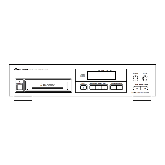
Page 32: Panel Facilities
1 , ¡ ¡ ¡ ) 10 MANUAL search buttons (1 4 , ¢ ¢ ¢ ¢ ¢ ) Î 11 TRACK search buttons (4 MULTI COMPACT DISC PLAYER REMOTE CONTROL UNIT 12 DELETE button CU-PD104 13 CLEAR button PD-M427...
Need help?
Do you have a question about the PD-M427 and is the answer not in the manual?
Questions and answers