Fujitsu ASU24CL1 Design & Technical Manual
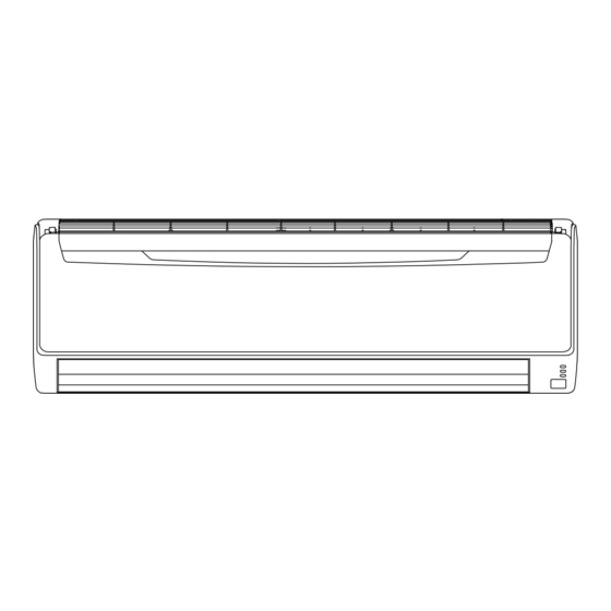
Wall mounted type
Hide thumbs
Also See for ASU24CL1:
- Operating manual (18 pages) ,
- Service manual (14 pages) ,
- Manual (48 pages)

Related Manuals for Fujitsu ASU24CL1


Summary of Contents for Fujitsu ASU24CL1
-
Page 1: Wall Mounted Type
AIR CONDITIONER Wall Mounted type DESIGN & TECHNICAL MANUAL INDOOR ASU24CL1 OUTDOOR AOU24CL1... -
Page 2: Indoor Unit
1. INDOOR UNIT WALL MOUNTED TYPE : ASU24CL1 DTR_AS046E_02 2010.12.02... -
Page 3: Table Of Contents
CONTENTS 1. INDOOR UNIT 1. FEATURE ........................01 - 01 2. WIRELESS REMOTE CONTROLLER ..........01 - 03 3. SPECIFICATIONS ....................01 - 05 4. DIMENSIONS ......................01 - 06 5. WIRING DIAGRAMS ..................01 - 07 6. CAPACITY TABLE .................... -
Page 4: Feature
FEATURE MODEL „ „ ASU24CL1 / AOU24CL1 FEATURES „ „ ALL DC „ High efficiency layout Large air flow and quiet DC fan motor operation by new air flow path fan motor PAM control PAM technology makes a compressor more powerful. - Page 5 Power diffuser „ “Healthy horizontal air flow” does not blow cool air directly at the occupants in the room. (ft.) Power diffuser 40 (ft.) Outside air conditions: 95 F 40% Operation contents: Cooling, Set temperature (Min set temp) ( F) F, Air flow Hi, Vertical flap : Upward Horizontal flap : Center...
-
Page 6: Wireless Remote Controller
WIRELESS REMOTE CONTROLLER FEATURES „ „ Four kinds of timer setup ¾ „ (On / Off / Program / Sleep) are possible. Four kinds of timers. Easy operation. ¾ „ Easy to change transmission code (4 patterns) by button operation. ¾... - Page 7 FUNCTIONS „ „ SLEEP button MASTER CONTROL button SET TEMP. button ( Signal transmitter TIMER MODE button TIMER SET ( ) button FAN CONTROL button START/STOP button SET button (Vertical) SET button (Horizontal) SWING button RESET button TEST RUN button •...
-
Page 8: Specifications
SPECIFICATIONS WALL MOUNTED Type COOLING ONLY INVERTER Model name ASU24CL1 Power source 202/230V ~ 60Hz Available voltage range 187-253V ~ 60Hz kW (W) 7.03 Rated BTU/h 24,000 Capacity Cooling 0.9 - 7.3 Min.-Max. BTU/h 3,100 - 25,000 Rated 2.40 Input power Cooling Min.-Max. -
Page 9: Dimensions
DIMENSIONS MODEL : ASU24CL1 „ „ Unit : in. (mm) 8-31/32 39-9/32 (998) (228) INSTALLATION PLACE „ „ Unit : in. (mm) Outline of unit 2-1/16 (52) or more 2-3/32 (53) or more 3-5/32 (80) or more 4-23/32 (120) or more... -
Page 10: Wiring Diagrams
WIRING DIAGRAMS MODEL : ASU24CL1 „ „ TEST CN13 EX.OUT (OPTION) EX.IN (OPTION) BLACK WHITE TO OUTDOOR UNIT - (01 - 07) -... -
Page 11: Capacity Table
CAPACITY TABLE 6-1. COOLING CAPACITY MODEL : ASU24CL1 „ „ Indoor temperature °FDB °FWB °FDB 15.0 19.7 15.7 1.04 21.9 15.8 1.05 22.7 17.1 1.05 24.9 18.6 1.07 26.4 18.5 1.07 27.9 19.7 1.08 19.7 15.3 1.20 21.1 15.4 1.22 21.8... -
Page 12: Fan Performance
FAN PERFORMANCE 7-1. AIR VELOCITY DISTRIBUTION Note: Fan speed : HIGH MODEL : ASU24CL1 „ „ Operation mode : FAN Unit : ft/s (m/s) (ft) 7(2) 3(1) 2(0.5) TOP VIEW Vertical flap : Up Horizontal flap : Center (ft) (ft) -
Page 13: Air Flow
7-2. AIR FLOW MODEL : ASU24CL1 „ „ Cooling „ Number of Fan speed rotations Air flow (r.p.m.) 1120 HIGH 1480 1220 1020 QUIET - (01 - 10) -... -
Page 14: Operation Noise
OPERATION NOISE 8-1. NOISE LEVEL CURVE MODEL : ASU24CL1 „ „ Cooling „ NC-65 NC-60 NC-55 NC-50 High NC-45 NC-40 NC-35 NC-30 NC-25 NC-20 Quiet NC-15 1,000 2,000 4,000 8,000 Octave band center frequency,Hz - (01 - 11) -... -
Page 15: Sound Level Check Point
8-2. SOUND LEVEL CHECK POINT 39-3/8 in. (1m) - (01 - 12) -... -
Page 16: Electric Characteristics
ELECTRIC CHARACTERISTICS Model name ASU24CL1 Voltage 208/230~ Power supply Frequency Max. operating current Connection cable *)Wiring Spec. Limited wiring length *) Wiring Spec. Selected Sample (Selected based on Japan Electrotechnical Standard and Codes Committee E0005) - (01 - 13) -... -
Page 17: Safety Devices
SAFETY DEVICES Model Protection form ASU24CL1 Circuit protection Current fuse (PCB) 3.15A 250V Terminal protection Current (thermal) fuse 3A 250V 215°F (102°C) °F (100 °C) OFF Fan motor protection Thermal protector program °F (95 °C) ON - (01 - 14) -... -
Page 18: External Input & Output
EXTERNAL INPUT & OUTPUT Connector INPUT OUTPUT REMARKS Control input See external CN14 (Operation / stop) input/output settings for details. CN16 Operation status output 11-1. EXTERNAL INPUT CONTROL INPUT (Operation/Stop) „ „ The air conditioner can be remotely operated by means of the following on-site work. Operation is started at the following contents by adding the contact input of a commercial ON/OFF switch to a connector on the external control PC board and turning it ON. -
Page 19: External Output
11-2. EXTERNAL OUTPUT OPERATION STATUS OUTPUT „ „ An air conditioner operation status signal can be output. Circuit diagram example „ Indoor Connected unit control PC board Connector Ex.)Relay unit Ex.)Display 24V DC Relay power supply *33 ft. (10 m) Signal Field supply * Make the distance from the PC board to the connected unit within 33ft. -
Page 20: Function Setting
FUNCTION SETTING 12-1. INDOOR UNIT INDOOR UNIT JM 5 Auto restart JM 6 Room temperature correction Jumper Wire JM 7 JM 8 Remote controller signal code JM 10 SWITCH POSITION „ „ MAIN PCB JM10 JM10 - (01 - 17) -... - Page 21 JUMPER WIRE SETTING „ „ Auto restart setting (JM5) „ ( Factory setting) JM 5 Auto restart Connect Validity Disconnect Invalidity Room temperature correction setting (JM6, JM7) „ ( Factory setting) Room temperature correction JM 6 JM 7 Cooling Drying Connect Connect...
-
Page 22: Optional Parts
OPTIONAL PARTS Exterior Parts name Model No. Summary SU MO TU WE TH FR SA Wired remote Unit control is performed by 3 6 9 12 15 18 21 UTB-UUB wired remote controller. controller Fine dust, invisible mold spores, and harmful microorganisms are absorbed Apple-catechin onto the filter by static... -
Page 23: Outdoor Unit
2. OUTDOOR UNIT SINGLE TYPE : AOU24CL1 DTR_AO068E_02 2010.12.02... - Page 24 CONTENTS 2. OUTDOOR UNIT 1. SPECIFICATIONS ....................02 - 01 2. DIMENSIONS ......................02 - 02 3. REFRIGERANT CIRCUIT ................02 - 03 4. WIRING DIAGRAMS ..................02 - 04 5. CAPACITY COMPENSATION RATE FOR PIPE LENGTH AND HEIGHT DIFFERENCE ..............
-
Page 25: Specifications
SPECIFICATIONS Type COOLING ONLY INVERTER Model name AOU24CL1 Power source 208/230V ~ 60Hz Available voltage range 187-253V ~ 60Hz Starting current 10.5 Airflow Cooling 1,554 (2,640) rate Type × Q'ty Propeller fan×1 Motor output Sound pressure level Cooling dB(A) inch 23-1/8 ×... -
Page 26: Dimensions
DIMENSIONS MODEL : AOU24CL1 „ „ Unit : in. (mm) Top view Front view Side view Air flow Bottom view INSTALLATION PLACE „ „ 3-15/16 (100) or more 3-15/16 (100) or more 11-13/16 (300) or more If the space is larger that is stated, the condition will be the same as that are no obstacles. - (02 - 02) -... -
Page 27: Refrigerant Circuit
REFRIGERANT CIRCUIT MODEL : AOU24CL1 „ „ Heat exchanger 3-Way ( INDOOR ) valve 2-Way valve Expansion valve Heat exchanger Strainer ( OUTDOOR ) Muffler Cooling Refrigerant pipe diameter Liquid : 1/4" (6.35 mm) Gas : 5/8" (15.88 mm) - (02 - 03) -... -
Page 28: Wiring Diagrams
WIRING DIAGRAMS MODEL : AOU24CL1 „ „ - (02 - 04) -... -
Page 29: Capacity Compensation Rate For Pipe Length
CAPACITY COMPENSATION RATE FOR PIPE LENGTH AND HEIGHT DIFFERENCE MODEL : AOU24CL1 „ „ Pipe length (m) COOLING 16ft. 25ft. 33ft. 49ft. 66ft. 82ft. 98ft. 66ft. 0.951 0.951 0.950 Û 1 33ft. 0.980 0.966 0.967 0.967 0.966 Indoor unit is upper than 25ft. -
Page 30: Additional Charge Calculation
ADDITIONAL CHARGE CALCULATION MODEL : AOU24CL1 „ „ Refrigerant type R410A lb. oz. 2lb. 13.9oz. Refrigerant amount 1300 Refrigerant charge „ ~ 49 Pipe length ~ 15 0.22oz./ft. (20g/m) 0 (Charge less) 10.6 Additional charge 0 (Charge less) +100 +200 +300 - (02 - 06) -... -
Page 31: Air Flow
AIR FLOW MODEL : AOU24CL1 „ „ Cooling „ Number of rotations Air flow (r.p.m.) 2640 m³/h 1100 1554 - (02 - 07) -... -
Page 32: Operation Noise
OPERATION NOISE 8-1. NOISE LEVEL CURVE MODEL : AOU24CL1 „ „ Cooling „ NC-65 NC-60 NC-55 NC-50 NC-45 NC-40 NC-35 NC-30 NC-25 NC-20 NC-15 1,000 2,000 4,000 8,000 Octave band center frequency,Hz - (02 - 08) -... -
Page 33: Sound Level Check Point
8-2. SOUND LEVEL CHECK POINT 39-3/8 in. (1m) - (02 - 09) -... -
Page 34: Electric Characteristics
ELECTRIC CHARACTERISTICS Model name AOU24CL1 Voltage 208/230 ~ Power supply Frequency *1) Max operating current 11.5 Starting Current 10.5 Main Fuse (Circuit breaker) Current *2) Wiring spec. Power Cable *3) Limited wiring length *1) The maximum current is the total current of indoor unit and outdoor unit. *2)Wiring spec. -
Page 35: Safety Devices
SAFETY DEVICES Model Protection form AOU24CL1 20A 250V Current fuse (NEAR THE TERMINAL) 5A 250V Circuit protection Current fuse 15A 250V (MAIN PRINTED CIRCUIT 3.15A 250V BOARD) OFF : 212±50°F (100±10°C) Fan motor protection Thermal protection program ON : 203±50°F (95±10°C) Compressor Thermal protection program OFF : 230°F (110°C)
Need help?
Do you have a question about the ASU24CL1 and is the answer not in the manual?
Questions and answers