Table of Contents
Advertisement
Quick Links
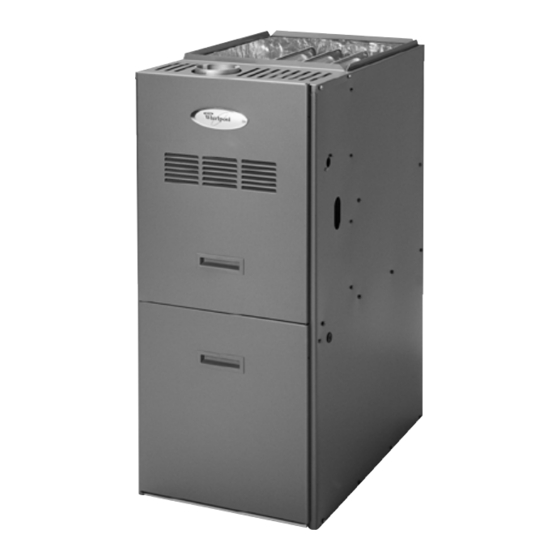
80% GAS FURNACE INSTALLATION INSTRUCTIONS
GAS FURNACE SAFETY................................................................1
INSTALLATION REQUIREMENTS ................................................3
Tools and Parts ............................................................................3
Location Requirements................................................................3
Installation Configurations ...........................................................4
Duct Work Requirements.............................................................6
Electrical Requirements ...............................................................6
Gas Supply Requirements ...........................................................6
Venting Requirements..................................................................6
INSTALLATION INSTRUCTIONS ..................................................8
Inspect Shipment .........................................................................8
Plan Vent System .........................................................................8
Connect Venting.........................................................................11
We have provided many important safety messages in this manual and on your appliance. Always read and obey all
safety messages.
This is the safety alert symbol.
This symbol alerts you to potential hazards that can kill or hurt you and others.
All safety messages will follow the safety alert symbol and either the word "DANGER" or
"WARNING." These words mean:
All safety messages will tell you what the potential hazard is, tell you how to reduce the chance of injury, and tell you
what can happen if the instructions are not followed.
Models WFAU, WFAR, WFAT
WFLU, WFLR, WFLT
46924D003
Table of Contents
GAS FURNACE SAFETY
Your safety and the safety of others are very important.
Install Duct Work ........................................................................11
Filter Specifications ....................................................................11
Make Electrical Connections .....................................................12
Make Gas Connections..............................................................13
Check the Furnace Input Rate ...................................................13
Adjust the Furnace Input Rate ...................................................14
Complete Installation..................................................................15
Sequence of Operation ..............................................................16
Controls ......................................................................................16
TROUBLESHOOTING ..................................................................17
ASSISTANCE OR SERVICE .........................................................20
Accessories ................................................................................20
You can be killed or seriously injured if you don't
immediately follow instructions.
You can be killed or seriously injured if you don't
follow instructions.
Whirlpool
®
Home Cooling and Heating
7901 S.W. 6th Court
Plantation, Florida 33324
Advertisement
Table of Contents

Related Manuals for Whirlpool WFAU


Summary of Contents for Whirlpool WFAU
-
Page 1: Table Of Contents
All safety messages will tell you what the potential hazard is, tell you how to reduce the chance of injury, and tell you what can happen if the instructions are not followed. Whirlpool ® Home Cooling and Heating Models WFAU, WFAR, WFAT 7901 S.W. 6th Court WFLU, WFLR, WFLT Plantation, Florida 33324 46924D003... -
Page 2: Save These Instructions
IMPORTANT SAFETY INSTRUCTIONS Use only with type of gas approved for this furnace. When a furnace is installed so that supply ducts carry Refer to the furnace rating plate. air circulated by the furnace to areas outside the space containing the furnace, the return air shall also Install this furnace only in a location and position as be handled by duct(s) sealed to the furnace casing specified in the Location Requirements section of... -
Page 3: Installation Requirements
Location Requirements INSTALLATION REQUIREMENTS These instructions are intended as a general guide only for use by qualified persons and do not supersede any national or local codes in any way. Compliance with all local, state, or national codes pertaining to this type of equipment should be determined prior to installation. -
Page 4: Installation Configurations
24.5 Installation Configurations Horizontal Installations Models WFAU and WFLU must be installed only as an upflow (Models WFAT and WFLT only) furnace. Models WFAT and WFLT may be installed as an upflow or horizontal furnace. Models WFAR and WFLR may be installed Airflow as either a counterflow or a horizontal furnace. - Page 5 Horizontal Installations Installation for Counterflow (Downflow) Models WFAR, WFLR, WFAT and WFLT model furnaces can be horizontally installed for airflow right to left or left to right. To WARNING ensure access to parts for servicing, install upflow and counterflow furnaces so that the burner and blower access panels are readily accessible.
-
Page 6: Duct Work Requirements
Combustible Floor Installation (Counterflow Models only) In all instances, other than wiring for the thermostat, the wiring to be done and any replacement of wire shall conform with the temperature limitation for Type T wire – 63°F (35°C) rise. The line voltage supply should be routed through a readily accessible disconnect located within sight of the furnace. - Page 7 Equipment in Confined Space (All Air from Inside) Equipment in Confined Space - All Air from Outside (All air through ventilated attic) 1. Chimney or gas vent 4. Outlet air 2. Furnace 5. Inlet air (Ends 12“ above bottom) 3. Ventilation louvers 6.
-
Page 8: Installation Instructions
Indoor air as the source of combustion air Inspect Shipment Indoor air as the source of combustion air is acceptable in most applications if the following guidelines are met: All provisions for indoor combustion air must meet the WARNING requirements for combustion air indicated in the National Fuel Gas Code, ANSI Z223.1/NFPA 54 (latest edition), and/or any Excessive Weight Hazard applicable local codes. - Page 9 Vent Option - Vent Through Roof Sidewall Venter Limitations Chart Vent pipe diameter 4 in. Less Than 10 Ft.(3048 mm) Minimum vent pipe length 4 ft 2 Ft. (610 mm) Maximum vent pipe length 25 ft * 3 Ft. Min. (914 mm) Maximum number of 90°...
- Page 10 Factory-Built Chimney Venting Existing Venting Systems When an existing furnace is removed or replaced, the original venting system may no longer be sized to properly vent the attached appliances. An improperly sized venting system can result in spillage of flue products into the living space, the formation of condensate, leakage, etc.
-
Page 11: Connect Venting
Connect Venting Filter Specifications 1. Using a ¹⁄₄ in. sheet metal screw, secure the vent pipe to the Filters are not supplied with these furnaces. It is the furnace inducer blower outlet. installer’s responsibility to install properly sized filters in accordance with the Minimum Filter Requirements chart. -
Page 12: Make Electrical Connections
5. Using UL listed wire nuts, connect the field supply wires to Make Electrical Connections the furnace (black to black and white to white). WARNING Electrical Shock Hazard Disconnect power before servicing. Replace all parts and panels before operating. Failure to do so can result in death or electrical shock. WARNING Thermostat Install a room thermostat according to the instructions furnished... -
Page 13: Make Gas Connections
7. Remove the inlet pressure tap plug on the gas control valve and connect pressure gauge to the ¹⁄₈ in. NPT inlet Make Gas Connections pressure tap. IMPORTANT: This furnace requires conversion for use with 8. Turn on the gas supply at the manual gas shutoff valve. propane. -
Page 14: Adjust The Furnace Input Rate
2. Regulator adjusting cap Manifold Pressure vs. Altitude Chart 3. Diagnostic LED ¹⁄₈ (Model WFAU 150 only) ” NPT Outlet pressure tap 5. Gas control switch Natural Gas 4. Be sure the gas control switch has been in the OFF position for at least 5 minutes before starting the unit. -
Page 15: Complete Installation
Adjust Blower Speed Complete Installation IMPORTANT: Do not use this furnace if any part has been under water. Immediately call a qualified person to inspect the furnace WARNING and to replace any part of the control system and gas control which has been under water. -
Page 16: Sequence Of Operation
Rollout Switch(es) Sequence of Operation The rollout switch(es) are normally closed switch(es) that open Heating when abnormal temperatures exist in the burner area. This can be caused by a restricted heat exchanger causing main burner A call for heat from the thermostat closes R to W on the blower flame to “roll out”... -
Page 17: Troubleshooting
Failure Codes TROUBLESHOOTING LED Status Fault Description (Flash Codes) No Power to the System Control Furnace Fails to Operate Properly Steady Flash* Normal Operation (Standby or call for heat) Review “Sequence of Operation” and visually inspect the following before troubleshooting: 2 Flashes Pressure switch closed when it should be Is the power to the furnace on? - Page 18 Wiring Connection Diagram - Honeywell ® SmartValve II ® Ignition System LINE VOLTAGE - FACTORY LINE VOLTAGE - FIELD LOW VOLTAGE - FACTORY LOW VOLTAGE - FIELD ROLLOUT ROLLOUT HIGH INDUCED SWITCH LIMIT SWITCH DRAFT (IF USED) BLOWER PRESSURE SWITCH SMARTVALVE LIMIT LIMIT...
- Page 19 Wiring Schematic - Honeywell ® SmartValve II ® Ignition System EAC(S) NEUTRALS (IF USED) INTERLOCK SWITCH CLEANER CONSTANT NEUTRALS HEAT CIRCULATION COOL NEUTRALS INDUCED HUMIDIFIER DRAFT BLOWER SMVII (IF USED) IGNITION CONTROL IGNITER (120 VAC) NEUTRALS 120 VAC TRANSFORMER 24 VAC BLOWER CONTROL CENTER T’STAT CONDENSER...
-
Page 20: Assistance Or Service
Combustible Floor Base (24.5" cabinets) Honeywell and SmartValve are trademarks of Honeywell International, Inc. 46924D003 ®/TM Whirlpool and all other trademarks are owned by Whirlpool, U.S.A., 4/03 © 2003. All rights reserved. used under license by Tradewinds Distributing Company, LLC.