
Related Manuals for Samsung B1445AVGW/YLW


Summary of Contents for Samsung B1445AVGW/YLW
-
Page 1: Table Of Contents
WASHING MACHINE B1445AVGW/YLW B1245AVGW/YLW B1045AGW/YLW SERVICE Manual WASHING MACHINE CONTENTS Caution for the safety during servicing 1. SPECIFICATIONS 2. SAFETY DEVICES 3. OVERVIEW OF THE WASHING MACHINE 4. OVERVIEW OF THE CONTROL PANEL 5. MAIN FUNCTION 6. TECHNICAL POINT 7. GENERAL ERROR FUNCTION 8. -
Page 2: Caution For The Safety During Servicing
CAUTION FOR THE SAFETY DURING SERVICING 1. Do not allow the customer to repair the product. ☞ The person may be injured or the product life may be shortened. 2. Execute A/S after unplugging the power supply unit. ☞ Be care of the electric shock. 3. -
Page 3: Specifications
1. SPECIFICATIONS WASH TYPE FRONT LOADING TYPE GROSS W 680mm X D 665mm X H 890mm DIMENSION W 598mm X D 550mm X H 844mm WATER PRESSURE 50 kPa ~ 800 kPa GROSS 78 kg WEIGHT 75 kg WASH and SPIN CAPACITY 6.0 kg (DRY LAUNDRY) 220 V 180 W... -
Page 4: Safety Devices
2. SAFETY DEVICES ※ We adapt 6 safety devices for users to use this wash machine safely. 1) Balancing device (ASSY-Main PCB) → When the laundry is out of balance, to prevent the noises and vibrations, the unbalance detecting sensor helps the laundry laid even and continue the dehydrating process. 2) Door locking device (DOOR-LOCK S/W) →... -
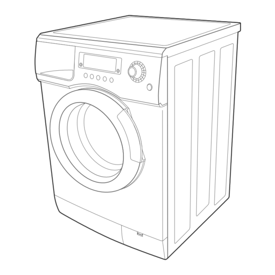
Page 5: Overview Of The Washing Machine
3. OVERVIEW OF THE WASHING MACHINE... -
Page 6: Overview Of The Control Panel
4. OVERVIEW OF THE CONTROL PANEL 1. Deterg ent disp enser 2. Disp lay panel Displays the remaining wash cycle time and error messages. 3. Silver Nano selection button Silver Nano water is supplied in washing as well as the last rinse, featuring sterilization and antibacterial coating. -
Page 7: Main Function
5. MAIN FUNCTION 1) Auto power S/W off function ● After power on, the auto power S/W off function automatically switches power off for you if you do not press selection button for 10 minutes ● After selecting the function, the auto power S/W off function automatically switches power off for you if you do not press start/pause button for 10 minutes ●... - Page 8 5. MAIN FUNCTION 8) Power-out compensation function ● If power is out on selected process, the process before power out is stored to EEPROM, once power is back the process before power out continues. ● When power is back, washing process starts from the process at the point of the power out, rinse/drain process starts from the initial process.
- Page 9 5. MAIN FUNCTION 10) Fuzzy washing function (weight-sensing) ☞ After finishing initial water supply, when the fall of the water level needs supplementary water supply, Sensing function perceives the weight with the supplementary water supply numbers and starts to work. Under the course of Cotton, or Coloureds, if the supplementary water supply numbers become over 2 times the function is going at default condition ( high water level ), if 1 time that is going at middle level, if 0 below low water level, heating hours and rinse hours depend on the above data.
- Page 10 5. MAIN FUNCTION 12) Unbalance detecting & laundry balance positioning system ① Just before the hydrating process and just after reversal rotation for balancing laundry position, this function is carried out ② The initial 6 sec is the period of reversal rotation for balancing laundry position , Drum rotates 50rpm for initial 6 sec ③...
-
Page 11: Technical Point
6. TECHNICAL POINT unit:sec 1) Motor on/off time at each course Washing Course Motor r.p.m Cotton Coloureds Synthetics Delicates Wool Handwash Quick B-Cotton B-Coloureds B-Delicates B-Stain 2) Final dehydrating r.p.m at each course unit:rpm Model B1445AV B1245AV B1045A Course 1400 1200 1000 Baby Cotton... - Page 12 6. TECHNICAL POINT 3) The water supply control at each process cycle Model B1445AV,B1245AV,B1045 Process cycle Pre Washing Cold water 5L/min Washing Cold water 10L/min + (Hot water 10L/min) Cold water 10L/min Rinse Final rinse Cold water 10L/min + Cold water 5L/min 4) The water level data at each course unit:Khz Water level...
- Page 13 6. TECHNICAL POINT 5) The other water level data unit:Khz The water data unter each conditon B1445AV , B1245AV, B1045A 25.50 1st water supply level to washing tub 1st water supply (only preparation) 21.50 The water supplied reach 2/3 of door Overflow error Bubble 24.50...
-
Page 14: General Error Function
7. General Error Function 1. An occurrence of an Error will make a sound of error melody for 5sec and continuously show one of the Error Displays from the following errors. (But, Fault Check Led will flash for 0.5sec.) 2. All of the steering parts will be off at that time until that error was released. 3. - Page 15 7. General Error Function 11. Natural Drain/Water Leak Error - If more than 4 times of water supply and safe water level of Heater are sensed for each course, this error will occur. - Display : "LE - This error will be released by turning off Power S/W. 12.
-
Page 16: Trouble Diagnosis
8. TROUBLE DIAGNOSIS - As the micom wash machine is configured of the complicate structure, there might be the service call. Below information is prepared for exact trouble diagnosis and suitable repair guide. Caution for the Repair and Replacement Please follow below instruction for the trouble diagnosis and parts replacement. 1) As some electronic components are damaged by the charged static electricity from the resin part of wash machine or the human body, prepare the human body earth or remove the potential difference of the human body and wash machine by contacting the power supply plug when the work contacting to PCB is... - Page 17 8-1. TROUBLE DIAGNOSIS Item Cause and treatment - Is the PCB connector connected well? - Is the voltage normal? - Is the power supply plug connected well? - Is the noise filter connected well? The power is not supplied - Is the secondary output of the power supply transformation normal? - Is the fuse disconnected? (option) •...
-
Page 18: Problem Checking And Method Of Pcb
8-2 . Problem Checking And Method Of PCB 8-2-1 The Part Of Power Source NO Power On The Voltage Of Between ⓐ and ⓑ Is Check The Trans As Big As 12V? The Voltage Of Check The Diode Between ⓒ and ⓓ Is (D11,D12,D16,D17,D18) As Big As 12V? And Condenser(CE3) - Page 19 8-2-2. Reset Part The Value Of Measurement Result Of Check The Power Source Between Micom 25 And Gnd Is 5V? Check IC4 7533 R40 100 CE7 1UF 8-2-3. Interrupt Part Check The Curve Check D11,12,16,17,18 Output Of ⓐ ? Check The Micom Check TR2,R35 Number 67 ? Check The Part Of...
- Page 20 8-2-4. Checking The Part Of An Oscillator When The Micom 22,23 Check, The Value Is Check Resonator 16Mhz? Exchange Micom And Check R42,R41 R41 68 RESO1 16MHz 8-2-5. Check The Part Of Buzzer ⓐ Part Confirm DC12V ? Check The Part Of Power Source Exchange BUZZER1, Check R5,R46 BUZZER1...
- Page 21 8-2-6. Driving Part Checking ◆ Confirm The Output Of DC5V, When The Every Part Of Micom Number Check, According To The Some Problem Condition ex) When The Drain Is Not Operating But Pump Motor Is Operating, Check The 5Voltage Of Micom Micom Number, 10 Is Micom Bad 5Voltage?
- Page 22 8-2-7. Confirm The Driving Part Of Motor Motor Is Not Spinning Check BD1, TRIAC5 Motor Is Not Turning Check RELAY1 Right And Left Check The Tacho Part MICOM IC 65003 COIL1 TRIAC5 1W 300 RELAY1...
- Page 23 8-2-8. Checking The Tacho Part Have The Motor Turn In Hand Is The Rectangular Check The Surroundings Curve In The Micom 66? Circuit And TR1,IC7 Exchange The Motor MICOM...
-
Page 24: Test Mode
9. TEST MODE 1. Driving Compartment Test Mode A. Hold down “ 1” and “ 2” keys simultaneously and then press POWER S/W “ 4” on. (Whole lamps turn on and display show “ t1” after 3 Seconds.) B. The driving compartment can be tested when you press “ 3” key right after entering into the initial stage of the TEST MODE. -
Page 25: Designation Of Main Components
10. DESIGNATION OF MAIN COMPONENTS 10-1 Normal / Reverse Revolution of Motor and R. P. M. Control 1 2 3 4 5 6 7 8 9 10 Rotor Stator coil Rotor Stator coil STATOR WASHING MOTOR <Figure1> <Figure2> ( ± 7%) STATOR(5.1) STATOR(5.1) ROTOR(8.9) TACHO(3.4) PROTECTOR(6.7) "H"(mm) Code-No. - Page 26 10-3 Heater 1) Capacity : AC 230V/2000W 2) Location : Bottom of TUB 3) Function : Raise the water temperature Thermistor supplied at the wash process. 4) Resistance value : 23~29 5) Thermal Fuse : 128° C 10-4 Detergent tub and water supply value A Detergent tub is composed of housing and 3 drawers .
- Page 27 10-6 Assy-tub Back INNER-BEARING OUT-BEARING OIL-SEAL (unit : mm) TYPE INNER-BEARING(A) OUT-BEARING(B) OIL-SEAL(C) Assy-Tub Back REMARK ø 30 ø 25 ø 34.1 DC97-00214E B1245AV,B1045A ø 30 ø 25 ø 34.1 DC97-00214D B1445AV 10-7 Assy- Drum (unit : mm) TYPE CODE-NO. REMARK ø...
-
Page 28: Pcb Schematic Diagram
11. PCB SCHEMATIC DIAGRAM... -
Page 29: Pcb Circuit Diagram
11-1. PCB CIRCUIT DIAGRAM This Document can not be used without Samsung's authorization. DGND 2.2K +12V LVT1 450mA 4.7K 1N4007 1N4007 KA7805A DGND 2.2K MMBT3904 100nF 1N4007 1N4007 1N4007 VAR3 MICOM1 10nF 4.7K 10nF 2200u 100K 470uF 100nF 100nF 100nF... -
Page 30: Pcb Circuit Diagram
11-2. PCB CIRCUIT DIAGRAM (AG-KIT) 90019WS-03... -
Page 31: Setting Up A Wash Machine
12. SETTING UP A WASH MACHINE 12-1 Remove the safety device for carriage 1) Remove 5 safety device volts with a enclosed wrench for safety device remove 2) Plug the 5 holes with 5 caps after removing the 5 safety device volts. * Take care of 5 safety device volts and a wrench , you need these when you move wash machine safely. - Page 32 12. SETTING UP A WASH MACHINE 3) Even though adjustment legs came out all the way, if machine is not leveled , prop up the machine with the wood or brick to make it even. (Do not use fragile material or slippery material such as laminated paper) 12-2-2 The condition of setting up sink( Disassembled Ass'y- Cover Top) 1) Spin the adjustment leg to the left and remove them from the front and rear side of the machine.
- Page 33 12. SETTING UP A WASH MACHINE Door Opening Dimension 12-3. 950 mm ② Side ① ● (When The Door Vertically Open ) The distance between door and the rear side is 760mm ① ② Upper ② ③ ① 340 mm 110 mm ●...
-
Page 34: Assemble And Disassemble
13. ASSEMBLE AND DISASSEMBLE 1. ASS’ Y-COVER TOP 1) Remove two screws fixing the top-cover on back side. 2) Push the top-cover back about 15mm and pull it up. SCREW 3) It’ s possible to exchange and service Assy-Panel (PCB), the pressure-sensor, the noise-filter, the water valve and trans(option). - Page 35 13. ASSEMBLE AND DISASSEMBLE 3. BELT 1) Remove the top-cover. 2) Disassemble and assemble the belt. 3) Check the belt is located at center of the motor-pulley. <When assemble the belt> Hook the belt on the motor pulley 1) and place it PULLEY around the pulley 2).
-
Page 36: Tools For Disassembly And Assembly
14. TOOLS FOR DISASSEMBLY AND ASSEMBLY TOOL 10mm Heater (1) Box driver 13mm Motor (1), Balance (5), 2 holes of each left and right of the shock absorber 19mm 1 Pulley hole Replaceable for the box driver. Double-ended 10, 13,19mm Since the bolt runs idle when the box driver is used, use the box spanner driver 17mm. - Page 37 15. TOP(FRONT) - EXPLODED VIEW P011 J014 C051 G007 Y001 G027 C010 G012 G013 V030 J006 G040 C062 G034 V010 G028 C053 V031 P002 V009 V001 V004 F004...
- Page 38 15. TUB - EXPLODED VIEW R070 R014 R020 R008 T031 R015 R018 V022 R016 R071 R003 R028 R013 V007 R021 R005 R007 R024 R010 R074 R006...
- Page 39 15. CASE - EXPLODED VIEW J001 M015 C007 J008 T024 J011 J012 J010 R030 C080 J012 G002 C023 R017 G003 P007 G018 R012 R012 G025 B006 G023 G020 G009 G015...
- Page 40 F004 DC64-00561D HANDLE-DOOR;Q1636V,ABS,-,-,-,-,SIL-SPRAY B1245AV,B1245AV F004 DC64-00561A HANDLE-DOOR;Q1636,ABS,-,-,-,-,WHT,TS-2 P B1045A G002 DC91-12102A ASSY-FIXER TUB;SWF-P12,- G003 DC97-00139F ASSY-HOSE DRAIN(O);P-PJT,PP/L1970/CHINA G007 DC97-05128A ASSY-PANEL FRONT;Q1636V/WHT,SAMSUNG/STAM B1245AV,B1245AV G007 DC97-05128B ASSY-PANEL FRONT;Q1636,WHT/SAMSUNG,NO-ST B1045A G009 DC90-11110K ASSY-PUMP DRAIN;SWF-P12,220V~240V/50Hz G012 DC64-00559C BUTTON-ENCODER;Q1636V,ABS,-,-,WHT,ICON G013 DC64-00565A BUTTON-PUSH;Q1636,ABS,-,-,WHT,TS-2 PJT G015 DC61-10673A CAP-DRAIN;SWF-P12,PP(TB53),-,-,-,WHT,-,...
- Page 41 15. PARTS LIST CODE NO. DESCRIPTION;SPECIFICATION REMARK P007 DC99-00524A ASSY-PAINT FRAME;B1445AV,CLON-PJT/WHT P011 DC61-01245A FRAME-PLATE(U);MW24-PJT,EGI,-,-,-,T0.8,- R003 DC91-12077A ASSY-CLAMP DIAPHGRAM;SWF-P12,TUB R005 DC97-01463F ASSY-DRUM;P1205/KRNJM,LEFTER TYPE/NEW-DR R006 DC47-00007A HEATER;-,DRUM-MDL,SUS316L,-,-,230V,20,-, R007 DC97-00214E ASSY-TUB BACK;SWF-P12/10,BACK/1200/INSID B1245AV,B1045A R007 DC97-00214D ASSY-TUB BACK;SWF-P14,BACK/1400/INSIDE-A B1445AV R008 6602-001072 BELT-TIMING GEAR;POLYURETHAN,L1270,J5,ME R010 DC61-00856A BRACKET-HEATER;SB-PJT,STS430,-,-,-,-,- R012...
- Page 42 16. SCREW BOLT LIST CODE NO. DESCRIPTION SPECIFICATION REMARK 6002-000471 SCREW-TAPPING TH,+,1,M4,L12,PASS,STS304 D-S/W+FRM-FRONT 6001-001773 SCREW-MACHINE TH,+,M5,L12, HINGE+FRAME 6002-001286 SCREW-TAPPING FH,+,1,M4,L16,NTR,STS304 C-DOOR+H-GLASS 6002-000213 SCREW-TAPPING TH,+,1,M4,L12,ZPC(YEL),SWRCH18 HOUSING-DRAWER 6002-000213 SCREW-TAPPING TH,+,1,M4,L12,ZPC(YEL),SWRCH18 SUB PCB-ASSY+FRAME 6002-000445 SCREW-TAPPING TH,+,2S,M4,L18,NTR,STS304 PANEL+FRM+HOUSING-D 6002-000554 SCREW-TAPPING PH,+,2S,M4,L12,ZPC(YEL),SWRCH1 HOUSING-DRAWER 6002-001327 SCREW-TAPPING PWH,+,1,M4,L12,NI PLT C/TOP+FRAME 6003-000226...
- Page 43 ELECTRONICS ©Samsung Electronics Co., Ltd. SEP. 2004 This Service Manual is a property of Samsung Electronics Co.,Ltd. Printed in Korea Any unauthorized use of Manual can be punished under applicable International and/or domestic law. Code No. : DC68-02290A...
- Page 44 15. TOP(FRONT) - EXPLODED VIEW P011 J014 C051 G007 Y001 G027 C010 G012 G013 V030 J006 G040 C062 G034 V010 G028 C053 V031 P002 V009 V001 V004 F004...
- Page 45 15. TUB - EXPLODED VIEW R070 R014 R020 R008 T031 R015 R018 V022 R016 R071 R003 R028 R013 V007 R021 R005 R007 R024 R010 R074 R006...
- Page 46 15. CASE - EXPLODED VIEW J001 M015 C007 J008 T024 J011 J012 J010 R030 R0021 J012 J010 G002 C023 R017 G003 P007 G018 R012 R012 G025 B006 G023 G020 G009 G015...
- Page 47 F004 DC64-00561D HANDLE-DOOR;Q1636V,ABS,-,-,-,-,SIL-SPRAY B1245AV,B1245AV F004 DC64-00561A HANDLE-DOOR;Q1636,ABS,-,-,-,-,WHT,TS-2 P B1045A G002 DC91-12102A ASSY-FIXER TUB;SWF-P12,- G003 DC97-00139F ASSY-HOSE DRAIN(O);P-PJT,PP/L1970/CHINA G007 DC97-05128A ASSY-PANEL FRONT;Q1636V/WHT,SAMSUNG/STAM B1245AV,B1245AV G007 DC97-05128B ASSY-PANEL FRONT;Q1636,WHT/SAMSUNG,NO-ST B1045A G009 DC90-11110K ASSY-PUMP DRAIN;SWF-P12,220V~240V/50Hz G012 DC64-00559C BUTTON-ENCODER;Q1636V,ABS,-,-,WHT,ICON G013 DC64-00565A BUTTON-PUSH;Q1636,ABS,-,-,WHT,TS-2 PJT G015 DC61-10673A CAP-DRAIN;SWF-P12,PP(TB53),-,-,-,WHT,-,...
- Page 48 15. PARTS LIST CODE NO. DESCRIPTION;SPECIFICATION REMARK P007 DC99-00524A ASSY-PAINT FRAME;B1445AV,CLON-PJT/WHT P011 DC61-01245A FRAME-PLATE(U);MW24-PJT,EGI,-,-,-,T0.8,- R003 DC91-12077A ASSY-CLAMP DIAPHGRAM;SWF-P12,TUB R005 DC97-01463F ASSY-DRUM;P1205/KRNJM,LEFTER TYPE/NEW-DR R006 DC47-00007A HEATER;-,DRUM-MDL,SUS316L,-,-,230V,20,-, R007 DC97-00214E ASSY-TUB BACK;SWF-P12/10,BACK/1200/INSID B1245AV,B1045A R007 DC97-00214D ASSY-TUB BACK;SWF-P14,BACK/1400/INSIDE-A B1445AV R008 6602-001072 BELT-TIMING GEAR;POLYURETHAN,L1270,J5,ME R010 DC61-00856A BRACKET-HEATER;SB-PJT,STS430,-,-,-,-,- R012...
- Page 49 16. SCREW BOLT LIST CODE NO. DESCRIPTION SPECIFICATION REMARK 6002-000471 SCREW-TAPPING TH,+,1,M4,L12,PASS,STS304 D-S/W+FRM-FRONT 6001-001773 SCREW-MACHINE TH,+,M5,L12, HINGE+FRAME 6002-001286 SCREW-TAPPING FH,+,1,M4,L16,NTR,STS304 C-DOOR+H-GLASS 6002-000213 SCREW-TAPPING TH,+,1,M4,L12,ZPC(YEL),SWRCH18 HOUSING-DRAWER 6002-000213 SCREW-TAPPING TH,+,1,M4,L12,ZPC(YEL),SWRCH18 SUB PCB-ASSY+FRAME 6002-000445 SCREW-TAPPING TH,+,2S,M4,L18,NTR,STS304 PANEL+FRM+HOUSING-D 6002-000554 SCREW-TAPPING PH,+,2S,M4,L12,ZPC(YEL),SWRCH1 HOUSING-DRAWER 6002-001327 SCREW-TAPPING PWH,+,1,M4,L12,NI PLT C/TOP+FRAME 6003-000226...
- Page 50 ELECTRONICS ©Samsung Electronics Co., Ltd. SEP. 2004 This Service Manual is a property of Samsung Electronics Co.,Ltd. Printed in Korea Any unauthorized use of Manual can be punished under applicable International and/or domestic law. Code No. : DC68-02290A...
Need help?
Do you have a question about the B1445AVGW/YLW and is the answer not in the manual?
Questions and answers