
Related Manuals for OJ Electronics WLM3


Summary of Contents for OJ Electronics WLM3
- Page 1 67345 02-15 (HKT) Installation Manual WLM3 WLTA3 WLTD3 WLDT3 WLCT3 www.ojelectronics.com © 2015 OJ Electronics A/S...
- Page 2 Area control for easy operation Flexible installation with wired and wireless connection Network communication for large applications Easy installation with plug and lead connections Outdoor temperature compensation (optional) Smart access with OJ FMS Gateway for FS Master (optional) © 2015 OJ Electronics A/S...
-
Page 3: Table Of Contents
Manual ContEnts WlM3 underfloor Heating Controller ..........4 Waterline add on Module - type WlM3-xao ......33 Description ..................7 Overall system configuration ............33 Product programme ................7 Technical specifications ..............33 Overall system configuration .............. 8 Waterline outdoor Compensation Module - type WloC3 ..34 installation .................. -
Page 4: Wlm3 Underfloor Heating Controller
WlM3 underfloor Heating Controller Wiring diagram WLM3-FS Continuously PE only COOLING SWITCH B1 B2 C1 C2 WLOC3 Top PCB String Unit number number To control X-OUTPUT (X-relay) DIP-5 DIP-6 DIP-7 (1-F) (1-9) for: ON / OFF Control WLM2 Compatible Boiler pump... - Page 5 1 2 3 4 5 6 7 8 9 10 X-RELAY Cooling device/module Commission mode Cooling device/module, Learn mode alternative Boiler test Differential thermostat Install mode * ON = Actuator output no. 1 is used as an ON/OFF signal for a dehumidifier © 2015 OJ Electronics A/S...
- Page 6 Wiring diagram WLM3-AO Continuously PE only WLOC3 © 2015 OJ Electronics A/S...
-
Page 7: Description
Description The WLM3 underfloor heating controller is suitable for connecting multiple room controllers/sensors and electric actuators (thermoheads) for an underfloor or radiator-based heating system. only oJ room controllers/sensors type Wlxx3 that are prepared for 2 wire or wireless communication can be used. For information on previous generations, see “special Features - replacing old masters”. -
Page 8: Overall System Configuration
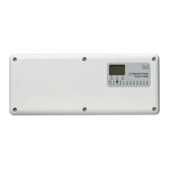
X-OUTPUT function active (see “Free relay function (X-OUTPUT)”). Type WLM3-xFS Secondary UFH pump running Boiler enabling signal active 1..8 Zones 1 to 8, indicating channel is active OJ Waterline Add-On WLM3 AO 9 10 11 12 13 14 Type WLM3-xAO © 2015 OJ Electronics A/S... -
Page 9: Installation
Attach the WLM3 master to a suitable wall. It will generally be convenient if the unit is situated within 0.8 m of the manifold, as most thermal actuators are supplied with 1 m cable. Cables can be run across the surface to the terminals using either the cable releases in the cover or by pressing out the cable entries in the lower part of the cover. -
Page 10: Pump Output
Delay times: Secondary UHF pump 180 sec. X-OUTPUT (configured as main pump) 190 sec. Free relay function (X-outPut) All WLM3 masters have a relay which can be to control X-outPut for: DiP-5 DiP-6 DiP-7 Fig. 6a utilized for a number of different purposes. - Page 11 X-relay to select the alternative energy source via a valve and/or pump. Fig. 6d High limit zone valve Bypass Application Sensor (High limit sensor) Supply water sensor (if fitted) MANIFOLD BOILER WLM3-BA/FS MASTER MANIFOLD © 2015 OJ Electronics A/S...
-
Page 12: Thermal Actuators (Thermoheads)
The voltage of the thermal actuators, 230V or 24V, must correspond that of the master. WLM3-xBA masters are for 230V thermal actuators, while WLM3-xFSmasters/add-on modules are for 24V thermal actuators. Up to 8 different zones can be controlled by the master. Connect the thermal actuator(s) on the loop(s) for each zone to the corresponding terminals on the master. -
Page 13: Room Sensors - Bus Connection
*) Up to 300 m if operation without backlight is acceptable. SENSORS/CONTROLLERS CONNECTED IN STAR SENSOR/CONTROLLERS CONNECTED IN BUS MODE SENSORS/CONTROLLERS CONNECTED IN BUS MODE SENSORS/CONTROLLERS CONNECTED IN STAR (DAISY CHAIN) (DAISY CHAIN) Fig. 9b Fig. 9c © 2015 OJ Electronics A/S... -
Page 14: Setting The Channel
(i.e. its channel number) can be set with a screwdriver (see fig. 10). Up to 14 channels can be set on the selector, and there are two auxiliary channels (see later). A WLM3 master has 8 outputs. It can be connected with an add-on slave module with an additional 6 outputs, creating a system with 14 individual zones. -
Page 15: Room Sensors - Wireless Setup
- wireless setup Fig. 11a WLxx3-29 wireless room sensors/controllers must be paired with a WLM3 master for wireless communication. To achieve this: 1. On the master, switch on DIP-3 to activate learning mode. 2. Initialize all wireless room controllers/sensors:... -
Page 16: Supply Water Sensor And Mixing Valve
Fig. 12a This feature, which limits supply water temperature, is available on full system masters, WLM3-xFS. The supply water sensor should be connected directly to the master via the terminals marked Supply Sensor. A temperature sensor of type ETF-522 must be used. -
Page 17: Interconnection Of Wlm3 Products
Similarly, a WLRC3 wireless receiver is connected to a WLM3 master using the plug-in connector provided with the receiver. For connecting a WLM3 master to another master in a network, a plug-in connector kit (WLM-NET) is available. CAT5 cable should always be used. -
Page 18: Special Functions
WLM3-BA/FS All masters must be interconnected using special cable via RJ14 socket 1 or 2. 4-port (For further information, see “Interconnection of WLM3 products”.) Network communication valve All masters must be connected in a daisy chain, NOT in a star formation (see WLM3-FS fig. -
Page 19: Using Cooling Functions
NOTE: For instructions on testing a network, see “Power-up recommendations”. using cooling functions WLAC 3 In addition to controlling heating, all WLM3 masters have the ability to control the cooling system. • T o enable the cooling function, a remote heating/cooling changeover module, WLAC3, and optional humidity sensor, WLHX3, must be connected. -
Page 20: Radiator Mode
• I f a dehumidifier is used, it can be connected via a relay using output 1 on the master and setting DIP-7 to “ON”. (NOTE: This output gives either 24V AC or 230V AC depending on the type of WLM3 master. -
Page 21: Hot Water Mode
• T he next numerical output on the WLM3 master MUST be used for the secondary/boost function. • When the system is in cooling mode, 2-step control will be disabled. • The 2-step controller is available in wired or wireless version. NOTE: To avoid overloading the WLM3 master, we recommend that the secondary output is used as a signalling function for a remote relay. -
Page 22: Commissioning Mode
Learn mode NOTE: This function conforms to BS/EN-1264 Part 4. Boiler test NOTE: Commissioning mode can only be activated on a WLM3-xFS master, and only if a supply water Install mode sensor is mounted. Otherwise, the function will be interrupted immediately. -
Page 23: Replacing Units
See “Installation” under “Waterline Room Sensors - Type WLTx”. If the sensor/controller is wired, proceed to step 7. 7. Check that the corresponding output LED has changed from flashing to permanently ON. 8. Reset DIP-3 to OFF. © 2015 OJ Electronics A/S... -
Page 24: Guidelines And Special Features
When the masters acting as network slaves are in install mode (DIP-1 is ON), their power LED will flash briefly whenever communication is detected (approx. every 3 sec). The WLM3-xFS network master features a menu option that allows the number of network slaves present on the system, and whether there are any errors, to be checked. -
Page 25: Factory Default Settings
Sensor timeouts Wired 300 sec. (5 min) Wireless 10000 sec. (2 h 45 min) Minimum supply water 16.0°C temperature for cooling Supply water PI-control P = 20.0°C temperature I = 300 sec. control © 2015 OJ Electronics A/S... -
Page 26: Error Indication
Error number will be indicated by the number of flashes, with a pause of less than a 1/2 second between flashes. Indication will be followed by a pause of 2 seconds, after which the sequence will be repeated. Error codes can also be seen in the service menu of WLM3-FS masters (submenu 2). - Page 27 A factory reset will return all programmed temperature settings to the factory defaults. It will also remove all room sensors/controllers from the master's memory and reset the system to accept only those room sensors/controllers that are functioning correctly. For information on reconnecting room sensors/controllers, see “Replacing equipment - Replacing a faulty sensor/controller”. © 2015 OJ Electronics A/S...
-
Page 28: Special Features
CHANNEL F OPERATION (Channel 15) By fitting a WLTM3 sensor to a WLM3 system, and setting its hex encoder to Channel F, a single override function can be used to override all the automatic time and temperature functions of the master, including those areas independently controlled by a WLCT3 room controller. -
Page 29: Replacing Old Masters
Backward compatibility must be considered if an old master is replaced with a new WLM3 master. If any of the connected room sensors or room controllers are of the old type, DIP-9 (WLM2 Compatible) must be switched to ON. -
Page 30: Valve And Pump Exercising
10 seconds during that period, and the mixing valve, if fitted, will be opened and closed. Certifications CE marking OJ Electronics A/S hereby declares that the product conforms with the following Directives of the European Parliament and of the Council: Master... -
Page 31: Technical Specifications
WLM3-1BA......... -
Page 32: 2015 Oj Electronics A/S
WLM3-1FS......... -
Page 33: Waterline Add On Module - Type Wlm3-Xao
Connect the AO module using the special cable included in the box. Connect a fused 230V AC mains supply. The sensor bus can be connected to either the WLM3 master or add-on module, using either bus (daisy chain) or star connections. Thermal actuators 1-8 are controlled by the WLM3 master while 9-14 are controlled by the add-on module. -
Page 34: Waterline Outdoor Compensation Module - Type Wloc3
Preset values are factory programmed but can easily be adjusted according to local needs via the display on the master. See the “Master with Display - Type WLM3” user manual for instructions on changing of the default factory settings. installation The unit should be mounted under the eaves of the roof or, alternatively, 2-3 metres above ground level. -
Page 35: Waterline Wireless Receiver - Type Wlrc3
Master Connect the receiver to the master, and the system will reconfigure itself for wireless operation. setting up the system See Quick Guide technical specifications See the Waterline Wireless Receiver Instructions © 2015 OJ Electronics A/S... -
Page 36: Waterline Room Controller - Type Wlct3
For installation instructions, see “Installation” under “Waterline Room Sensors - Type WLTx3”. getting started Buttons Fig. 1 Display Adjustment down OK - Accept Adjustment up Reset to factory Pinhole button for settings clock adjustment © 2015 OJ Electronics A/S... - Page 37 OK (√) button. Then press the UP (△) or DOWN (▽) button to select the correct day and press the OK (√) button to confirm. AREA SETUP - see next page. © 2015 OJ Electronics A/S...
- Page 38 Set the channel/room (Ch) to ON if it is to follow the settings of this room controller. A total of 14 channels/rooms can be controlled. NOTE: If the channel selector (hex encoder) is set to 1 .. 14, the selected channel will always be ON (cannot be set to OFF). © 2015 OJ Electronics A/S...
-
Page 39: Everyday Use Of The Room Controller
DOWN (▽) button until the override temperature is set. The set temperature will remain on the display and the unit will continue to operate to this temperature permanently. Cancelling manual mode To cancel permanent override, press the OK (√) button once, and the unit will resume automatic operation. © 2015 OJ Electronics A/S... -
Page 40: Programming 4-Event Times And Temperatures
5°C and then pressing the DOWN (▽) button once Days 6-7 more. notE: When programming the “sleep” time (event 4), ensure : Time and temperature that it is before midnight (00:00). : Time and temperature © 2015 OJ Electronics A/S... -
Page 41: Advanced Settings And Read-Outs
Operates the channel as a radiator zone. Operates as an ON/OFF regulator, activates the X-OUTPUT and boiler (but not the UFH pump). Channels selected in the ArEA menu will also act as radiator channels. © 2015 OJ Electronics A/S... - Page 42 Operates the channel as a thermostat for a domestic hot water cylinder. Operates as an ON/OFF regulator, activates the X-OUTPUT and boiler (but not the UFH pump). Press the OK (√) button to return to the APP menu. © 2015 OJ Electronics A/S...
- Page 43 DOWN button once more. Remember that the max. limit temperature must be set higher than the min. limit temperature. The limit temperatures defined in the room controller will be valid for all room sensors with floor limit sensor (type WLTD3) included in the area allocated to the WLCT3 controller. © 2015 OJ Electronics A/S...
- Page 44 Example: A system may have the kitchen room sensor operating master output #4 and the children’s room sensor operating master output #5. If the WLCT3 room controller is situated in the living room and operates output #1, the WLCT3 must be programmed to control output channels 1, 4, & 5. © 2015 OJ Electronics A/S...
- Page 45 Press the UP (△) or DOWN (▽) button to switch between ON and OFF. Press the OK (√) button to confirm. EsC - Escape Press the OK (√) button to end programming and return to the scheduled programme. © 2015 OJ Electronics A/S...
-
Page 46: Reset To Factory Settings - Room Controllers
Ch 2 living room 2-step time 60 min Write the room name in the box beside 2-step temperature each Ch number, and add ON if it is 2.0°C difference controlled by a clock thermostat. © 2015 OJ Electronics A/S... -
Page 47: Radiator Mode
Where a radiator circuit is used, it is possible to control room temperature using a special WLCT3 mode called Radiator Mode, thus optimizing energy savings. The controller measures the temperature in the room, and a zone valve is then controlled via the WLM3 master, which in turn activates the boiler on demand. -
Page 48: Waterline Room Sensor With Display - Type Wldt3
Adjustment down OK - Accept Adjustment up Reset to factory settings Wireless initialize button (no function on hardwired versions) Display Auto mode Indication of actual Manual comfort mode room temperature and Manual setback mode setpoint offset. © 2015 OJ Electronics A/S... -
Page 49: Everyday Use
In setback mode OFF is shown. The temperature is now controlled only by the master's frost protection setpoint (factory setting 5°C), overriding any programmed 4-event schedules in the system. The system is now off, but still with frost protection enabled. © 2015 OJ Electronics A/S... -
Page 50: Advanced Settings And Read-Outs
Press the UP (△) or DOWN (▽) button to change the setting. Confirm the required scale with the OK (√) button. ESC - Escape Press the OK (√) button to end programming and return to normal operation. Batteries For information on batteries, see “Batteries” under “Waterline Room Sensors - Type WLTx3”. © 2015 OJ Electronics A/S... -
Page 51: Waterline Room Sensors - Type Wltx3
Remove the plastic battery pull tab. The plastic battery pull tab may not be removed before the master is in learning mode. For further information, see “Installation - Room Sensors - Wireless Setup”. Room sensors Room sensors connected in star connected in formation daisy chain © 2015 OJ Electronics A/S... -
Page 52: Installation
(i.e. its channel number) can be set with a screwdriver (see fig. 10). Up to 14 channels can be set on the selector, and there are two auxiliary channels with special functions. A WLM3 master has 8 outputs and additional slave modules, each with 6 outputs, can be connected creating a system of 14 individual zones. -
Page 53: Setting Room Temperature
The master is supplied with default temperature settings which are used by all room sensors connected to the system. With WLM3-xBA masters, the default DAY, NIGHT and OFF temperature settings are fixed (see “Factory Default Settings”) . -
Page 54: Batteries (Wireless)
MIN. or MAX. temperature control. If set for MAX., the limit setting will be 27°C. If set for MIN., the limit setting will be 17°C. These temperatures are fixed when used with WLM3- xBA masters unless the room sensor has been allocated to a zone group controlled by a WLCT3 room controller. - Page 55 © 2015 OJ Electronics A/S...
Need help?
Do you have a question about the WLM3 and is the answer not in the manual?
Questions and answers
I want to know where I can buy this controller and the floor heating controller