Advertisement
Quick Links
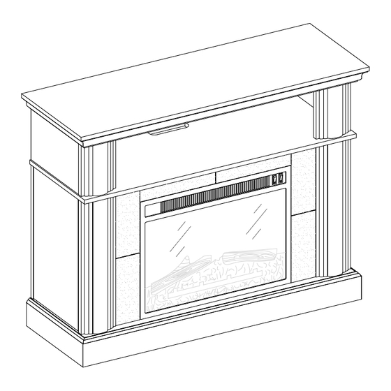
44" Media Fireplace in Cherry Finish
If you have any questions regarding assembly or if parts are missing, DO NOT return this item to the
store where it was purchased. Please call our customer service number and have your instructions
and parts list ready to provide the model name, part name or factory number:
Or visit our web site 24 hours a day, 7 days a week for product assistance at
THIS INSTRUCTION BOOKLET CONTAINS IMPORTANT SAFETY INFORMATION.
PLEASE READ AND KEEP FOR FUTURE REFERENCE.
Whalen Furniture Manufacturing
Stock # BH15-084-899-09
ADULT ASSEMBLY AND SET-UP REQUIRED
Pacific Standard Time: 8:30 a.m. - 4:30 p.m., Monday - Friday
Or e-mail your request to parts@whalenfurniture.com
Date 2015-05-18 Rev. 2 Factory: NIELFU
1-866-942-5362
www.whalenstyle.com
Page 1
LOT NUMBER:
DATE PURCHASED:
Factory No. 17052
/
/
Advertisement

Subscribe to Our Youtube Channel
Related Manuals for better homes BH15-084-899-09


Summary of Contents for better homes BH15-084-899-09
- Page 1 LOT NUMBER: DATE PURCHASED: 44" Media Fireplace in Cherry Finish Stock # BH15-084-899-09 ADULT ASSEMBLY AND SET-UP REQUIRED If you have any questions regarding assembly or if parts are missing, DO NOT return this item to the store where it was purchased. Please call our customer service number and have your instructions...
-
Page 2: Quality Guarantee
M A X I M U M R E C O M M E N D E D W E I G H T L O A D S MANUFACTURER: Whalen Furniture Manufacturing CATALOG: 44" Media Fireplace in Cherry Finish (BH15-084-899-09) DATE OF MANUFACTURE: May 2015 MADE IN CHINA FITS UP TO MOST 54”... - Page 3 Stock # BH15-084-899-09 Important Before you begin: Open, identify and count all parts prior to assembly. Lay out parts on a flat and non- abrasive surface. You will need the parts identified on page 4 and 5 of this instruction manual.
-
Page 4: Parts And Hardware List
Stock # BH15-084-899-09 Parts and Hardware List Please read completely through the instructions and verify that all listed parts and hardware are present before beginning assembly. A- Top Panel (1) B- Left Upper Side Panel (1) C- Right Upper Side Panel (1) - Page 5 Stock # BH15-084-899-09 Parts and Hardware List Please read completely through the instructions and verify that all listed parts and hardware are present before beginning assembly. (1) Cam Lock (2) Cam Bolt (3) M8 x 30 mm Wood Dowel (35+1 extra)
-
Page 6: Assembly Instructions
Stock # BH15-084-899-09 Assembly Instructions Pivot Pin Bushing (4 used in this step) ⑮ 1. Unpack the unit and confirm that you have all the hardware and required parts. Assembly the unit on a carpeted floor or the empty carton to avoid any scratch. - Page 7 Stock # BH15-084-899-09 Assembly Instructions A/D/E F/L/ I /J Cam Bolt (35 used in this step) ② 3. Securely screw the Cam Bolts (2) into the designate small holes on the Top Panel (A), Center Shelf (F), Base (L), Upper Front Panels (D and E) and Lower Front Panels (I and J) by a Phillips screwdriver. As shown.
- Page 8 Stock # BH15-084-899-09 Assembly Instructions Cam Lock (4 used in this step) ① M8 x 30 mm Wood Dowel (2 used in this step) ③ 4. Insert one Wood Dowel (3) into the center end hole of the Left Upper Side Panel (B). Tap it in with a rubber mallet, if necessary.
- Page 9 Stock # BH15-084-899-09 Assembly Instructions Ø4 x 38 mm Screw Cam Lock M8 x 30 mm Wood Dowel (4 used in this step) (6 used in this step) (8 used in this step) ⑤ ① ③ 7. Insert four Wood Dowels (3) into the inner holes of Left Lower Side Panel (G) at both ends. Align and ttach the Left Lower Side Panel (G) between the Left Lower Front Panel (I) and one Lower Back Panel (N) with three Cam Locks (1) and two 38 mm Screws (5) as shown.
- Page 10 Stock # BH15-084-899-09 Assembly Instructions Push Magnetic Catch (2 used in this step) ⑩ M8 x 30 mm Wood Dowel Cam Lock Ø3.5 x 15 mm Pan Head Screw (2 used in this step) (3 used in this step) (8 used in this step) ③...
- Page 11 Stock # BH15-084-899-09 Assembly Instructions Cam Lock (6 used in this step) ① M8 x 30 mm Wood Dowel (6 used in this step) ③ 11. Insert six Wood Dowels (3) into the drilled holes on the assembled Upper Panels (B, C, D and E) and attach them to the Top Panel (A) by engaging six Cam Locks (1).
- Page 12 Stock # BH15-084-899-09 Assembly Instructions M8 x 30 mm Wood Dowel Ø4 x 38 mm Screw (6 used in this step) (6 used in this step) ③ ⑤ 12. Insert six Wood Dowels (3) into the inner holes at the bottom of the Upper Panels (B, C, D and E).
- Page 13 Stock # BH15-084-899-09 Assembly Instructions Cam Lock M8 x 30 mm Wood Dowel (12 used in this step) (6 used in this step) ① ③ 14. Insert six Wood Dowels (3) into the top inner holes of both Lower Side Panels (G and H) and Lower Back Panels (N).
- Page 14 Stock # BH15-084-899-09 Assembly Instructions M8 x 30 mm Wood Dowel Cam Lock Ø4 x 38 mm Screw (8 used in this step) (4 used in this step) (8 used in this step) ③ ① ⑤ 16. Align and attach the Base (L) to last assembly with four Cam Locks (1), eight Wood Dowels (3) and eight 38 mm Screws (5).
- Page 15 Stock # BH15-084-899-09 Assembly Instructions Ø3.5 x 12 mm Metal Bracket Screw (4 used in this step) (2 used in this step) ⑧ ④ 17. Stand the assembled unit upright. 18. With the pilot holes as a guide, fasten the Center Crossbar (K) to the Lower Front Panels (I and J) by attaching two Metal Brackets (8) at the joints, using two 12 mm Screws (4) per bracket.
- Page 16 Stock # BH15-084-899-09 Assembly Instructions Ø3.5 x 15 mm Washer Head Screw (16 used in this step) ⑥ 19. Now, go back and securely tighten all the Cam Locks and the Screws. Make sure that all the parts are tight and there are no gaps between the parts.
- Page 17 Stock # BH15-084-899-09 Assembly Instructions Left Bottom Pivot Hinge Left Upper Pivot Hinge Ø3.5 x 12 mm Screw (1 used in this step) (1 used in this step) (4 used in this step) ⑫ ⑪ ④ 21. Attach one pair of Pivot Hinges (11 and 12) to the Pivot Pin Bushings (15) in the Center Shelf (F) and Base (L) as shown.
- Page 18 Stock # BH15-084-899-09 Assembly Instructions Right Upper Pivot Hinge Right Lower Pivot Hinge Ø3.5 x 12 mm Screw (1 used in this step) (1 used in this step) (4 used in this step) ⑫ ⑪ ④ 23. Repeat the same procedure with the Right Door (Q).
- Page 19 Stock # BH15-084-899-09 Assembly Instructions G/H/ /J/N G/H/ B/C/G/H/ /J/N /J/N Cam Lock Cover Shelf Support (20 used in this step) (8 used in this step) ⑦ ⑬ 24. Open the Doors (P and Q) and insert four Shelf Support s (13) into the desired holes inside each side compartment.
- Page 20 Stock # BH15-084-899-09 Assembly Instructions Fireplace 26. Unpack the fireplace insert from the inner box and follow the instructions to install the Top Trim and Side Trims to the fireplace insert. 27. Lift the fireplace insert carefully into the back of the assembled mantel and center it in the opening.
- Page 21 Stock # BH15-084-899-09 Assembly Instructions Acrylic Stopper (1 used in this step) ⑨ NOTE: You must install the Acrylic TV Stopper to prevent the TV from tipping when placing your flat panel television directly on the Top Panel. 28. Remove the paper backing of Acrylic Stopper (9), then properly align the Acrylic Stopper into the cut-out on the acrylic stopper template on the front of Top Panel (A).
- Page 22 Stock # BH15-084-899-09 Assembly Instructions Tools required: Phillips Screwdriver, Power Drill, 3/8” Drill Bit and Rubber Mallet. 30. Ask for assistance to position the assembled mantel at the desired location against a wall. 31. Now, follow the instructions printed on the plastic bag containing the Tipping Restraint Hardware to attach the tip-over restraints to the unit and the wall, as shown in the illustration.
-
Page 23: Care And Maintenance
Stock # BH15-084-899-09 Care and Maintenance Use a soft, clean cloth that will not scratch the surface when dusting. Use of furniture polishes is not necessary. Should you choose to use polishes, test first in an inconspicuous area.
Need help?
Do you have a question about the BH15-084-899-09 and is the answer not in the manual?
Questions and answers