Advertisement
Quick Links
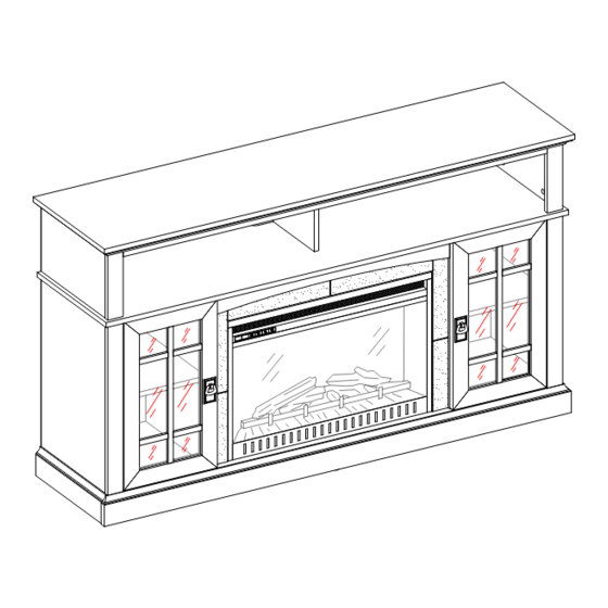
60" Media Fireplace in Black Mission Finish
If you have any questions regarding assembly or if parts are missing, DO NOT return this item to the
store where it was purchased. Please call our customer service number and have your instructions
and parts list ready to provide the model name, part name or factory number:
Or visit our web site 24 hours a day, 7 days a week for product assistance at
THIS INSTRUCTION BOOKLET CONTAINS IMPORTANT SAFETY INFORMATION.
PLEASE READ AND KEEP FOR FUTURE REFERENCE.
Whalen Furniture Manufacturing
Stock # BH15-084-899-12
ADULT ASSEMBLY AND SET-UP REQUIRED
Pacific Standard Time: 8:30 a.m. - 4:30 p.m., Monday - Friday
Or e-mail your request to parts@whalenfurniture.com
Date 2015-06-09 Rev. 2 Factory: KONRIC
1-866-942-5362
www.whalenstyle.com
Page 1
LOT NUMBER:
DATE PURCHASED: /
Factory No. 16086
/
Advertisement

Subscribe to Our Youtube Channel
Related Manuals for better homes BH15-084-899-12


Summary of Contents for better homes BH15-084-899-12
- Page 1 LOT NUMBER: DATE PURCHASED: / 60" Media Fireplace in Black Mission Finish Stock # BH15-084-899-12 ADULT ASSEMBLY AND SET-UP REQUIRED If you have any questions regarding assembly or if parts are missing, DO NOT return this item to the store where it was purchased. Please call our customer service number and have your instructions...
- Page 2 M A X I M U M R E C O M M E N D E D W E I G H T L O A D S MANUFACTURER: Whalen Furniture Manufacturing CATALOG: 60" Media Fireplace in Black Mission Finish (BH15-084-899-12) DATE OF MANUFACTURE: June 2015 MADE IN CHINA FITS UP TO MOST 65”...
- Page 3 Stock # BH15-084-899-12 Important Before you begin: Open, identify and count all parts prior to assembly. Lay out parts on a flat and non- abrasive surface. You will need the parts identified on page 4 and 5 of this instruction manual.
-
Page 4: Parts And Hardware List
Stock # BH15-084-899-12 Parts and Hardware List Please read completely through the instructions and verify that all listed parts and hardware are present before beginning assembly. A- Top Panel (1) B- Upper Side Panel (2) C- Upper Partition Panel (1) - Page 5 Stock # BH15-084-899-12 Parts and Hardware List Fireplace Insert (1) Remote Control with Battery (1) (1) Cam Lock (2) Cam Bolt (3) Ø8 x 30 mm Wood Dowel (35+1 extra) (35+1 extra) (34+1 extra) (4) Ø3.5 x 12 mm Screw (5) Ø4 x 25 mm Screw...
-
Page 6: Assembly Instructions
Stock # BH15-084-899-12 Assembly Instructions A/J/E/F Cam Bolt (18 used in this step) ② 1. Unpack the unit and confirm that you have all the hardware and required parts. Assembly the unit on a carpeted floor or the empty carton to avoid any scratch. - Page 7 Stock # BH15-084-899-12 Assembly Instructions Cam Bolt (11 used in this step) ② 3. Securely screw the Cam Bolts (2) into the designated small holes on the Fixed Shelf (D) as shown. 1-866-942-5362 Please call for replacement parts or assistance:...
- Page 8 Stock # BH15-084-899-12 Assembly Instructions Cam Lock Wood Dowel (3 used in this step) (2 used in this step) ① ③ 4. Insert two Wood Dowels (3) into the inner holes of Middle Crossbar Assembly (I). Tap it in with a rubber mallet, if necessary.
- Page 9 Stock # BH15-084-899-12 Assembly Instructions Cam Lock Wood Dowel (6 used in this step) (4 used in this step) ① ③ 6. Align and attach the Bottom Rear Stretcher (L) to the Bottom Panel (J) by using two wood dowels (3) and three cam locks (1).
- Page 10 Stock # BH15-084-899-12 Assembly Instructions Cam Lock Wood Dowel (6 used in this step) (6 used in this step) ① ③ 8. Insert six Wood Dowels (3) into the large holes of the assembled base at both ends. 9. Align the large holes on Left Lower Side Panel (E) with the inserted Wood Dowels (3) on the assembled base.
- Page 11 Stock # BH15-084-899-12 Assembly Instructions Wood Dowel Ø4 x 40 mm Wood Screw (4 used in this step) (4 used in this step) ③ ⑥ 11. Insert four Wood Dowels (3) into the inner holes of the Lower Partition Panels (G and H) and attach them to the Bottom Panel (J) by using four 40 mm Wood Screws (6).
- Page 12 Stock # BH15-084-899-12 Assembly Instructions Cam Lock Wood Dowel (8 used in this step) (8 used in this step) ① ③ 12. Insert eight Wood Dowels (3) into the inner holes on the top edge of the Lower Side Panels and Partition Panels (E, F, G and H).
- Page 13 Stock # BH15-084-899-12 Assembly Instructions Ø3.5 x 12 mm Screw Angle Metal Bracket (8 used in this step) (2 used in this step) ④ ⑫ 14. With the pilot holes as a guide, align and attach two Angle Metal Brackets (12) to the front corners of the assembled base, using four 12 mm Screws (4) per bracket.
- Page 14 Stock # BH15-084-899-12 Assembly Instructions Floor Leveler (2 used in this step) ⑬ 15. Screw two Floor Levelers (13) into the threaded sockets on the Angle Metal Brackets (12). 1-866-942-5362 Please call for replacement parts or assistance: Whalen Furniture Manufacturing Page 14 Factory No.
- Page 15 Stock # BH15-084-899-12 Assembly Instructions Cam Bolt (6 used in this step) ② 16. Stand the assembled unit upright. 17. Securely screw six Cam Bolts (2) into the designated small holes on the Fixed Shelf (D) by a Phillips screwdriver.
- Page 16 Stock # BH15-084-899-12 Assembly Instructions Cam Lock (6 used in this step) ① Wood Dowel (5 used in this step) ③ 18. Insert five Wood Dowels (3) into the large holes on the Fixed Shelf (D). Attach the Upper Side Panels (B) and Partition Panel (C) to the Fixed Shelf (D) by using six Cam Locks (1).
- Page 17 Stock # BH15-084-899-12 Assembly Instructions Cam Lock (6 used in this step) ① Wood Dowel (5 used in this step) ③ 19. Insert five Wood Dowels (3) into the top inner holes of the Upper Partition Panel (C) and Side Panels (B).
- Page 18 Stock # BH15-084-899-12 Assembly Instructions Ø3.5 x 12 mm Screw Straight Metal Bracket (4 used in this step) (2 used in this step) ④ ⑨ Ø4 x 25 mm Screw (2 used in this step) ⑤ 20. Fasten the Middle Crossbar Assembly (I) to the stringers of Lower Partition Panels (G and H) by attaching two Straight Metal Brackets (9) at the joints, using two 12 mm Screws (4) per Bracket.
- Page 19 Stock # BH15-084-899-12 Assembly Instructions M3.5 x 15 mm Washer Head Screw (30 used in this step) ⑦ 22. Pick up the Upper Back Panel (O) and align the pre-drilled holes against the upper long edge with the pilot holes on the back stretcher of Top Panel (A). Attach the Back Panel (O) in place using the provided Washer Head Screws (7).
- Page 20 Stock # BH15-084-899-12 Assembly Instructions E/F/G/H E/F/G/H Shelf Pin Cam Lock Cover (8 used in this step) (26 used in this step) ⑮ ⑯ 24. Insert four Shelf Pins (15) into the holes at your desired height inside each side compartment. Tilt and rest the Adjustable Shelves (R) onto the Shelf Pins (15).
- Page 21 Stock # BH15-084-899-12 Assembly Instructions Rubber Bumper (4 used in this step) ⑭ 26. Pick up the Left Door (N) and attach the extended Hinge Arms to the Hinge Bases installed on the Left Lower Side Panel (E). Loosen the bolt on the back of Hinge Base for an easy fit. Align and insert the “U”...
- Page 22 Stock # BH15-084-899-12 Assembly Instructions Handle and Back Plate Handle Bolt (2 used in this step) (2 used in this step) ⑩ ⑪ 30. Attach one Handle and Back Plate (10) to the front side of each Door (M and N) with the provided Handle Bolt (11).
- Page 23 Stock # BH15-084-899-12 Assembly Instructions 31. Lift the Fireplace Insert carefully into the back of the assembled mantel and center it in the opening. drag the insert across the Bottom Panel (J) as it may scratch the unit. 1-866-942-5362 Please call for replacement parts or assistance:...
- Page 24 Stock # BH15-084-899-12 Assembly Instructions 2” Lag Bolt (2 used in this step) ⑧ 32. Align and attach the Firebox Support (Q) to the Bottom Panel (J) by screwing two 2” Lag Bolts (8) through the countersunk holes and screw into place.
- Page 25 Stock # BH15-084-899-12 Assembly Instructions Acrylic Stopper (1 used in this step) ⑰ NOTE: You must install the Acrylic TV Stopper to prevent the TV from tipping when placing your flat panel television directly on the console. 33. Remove the paper backing of acrylic stopper (17), then properly align the acrylic stopper into the cut-out on the acrylic stopper template on the Top Panel (A).
- Page 26 Stock # BH15-084-899-12 Assembly Instructions Tools required: Phillips screwdriver, Power Drill, 3/8” Drill Bit and Rubber Mallet. 35. Ask for assistance to position the assemble fireplace at the desired location against a wall. If necessary, adjust the pre-attached Floor Levelers at the bottom of the Base to level the unit. Now, follow the instructions printed on the plastic bag containing the Tipping Restraint Hardware to attach the tip-over restraints to the unit and the wall.
-
Page 27: Care And Maintenance
Stock # BH15-084-899-12 Care and Maintenance Use a soft, clean cloth that will not scratch the surface when dusting. Use of furniture polish is not necessary. Should you choose to use polish, test first in an inconspicuous area. - Page 28 IF YOU NEED TO ORDER ANY REPLACEMENT PARTS, PLEASE USE THE LIST BELOW 60" Media Fireplace in Cherry Finish (BH15-084-899-11) *BH15-084-899-11-1-TP Top Panel *BH15-084-899-11-26-SP Shelf Pin *BH15-084-899-11-2-USP Upper Side Panel *BH15-084-899-11-27-M8x30WD M8 x 30 mm Wood Dowel *BH15-084-899-11-3-LSP Lower Side Panel *BH15-084-899-11-28-MB Metal Bracket *BH15-084-899-11-4-UPP...
Need help?
Do you have a question about the BH15-084-899-12 and is the answer not in the manual?
Questions and answers