Table of Contents
Advertisement
CONTENTS
OPERATION AND WIRING DIAGRAMS................ 2
REPAIR GUIDE...................................................... 9
SPARE PARTS LIST...............................................17
REPAIR SHEET...................................................... 19
" r e p a r a t i o n
TROUBLESHOOTING
TROUBLESHOOTING
TROUBLESHOOTING
TROUBLESHOOTING
AND REPAIR MANUAL
AND REPAIR MANUAL
AND REPAIR MANUAL
AND REPAIR MANUAL
PAGE
2
3
5
6
9
10
10
13
15
n o
inver ter
p r o b l e m ! "
cod. 988656
Advertisement
Table of Contents

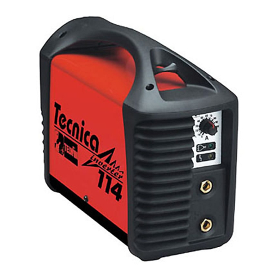
Related Manuals for Telwin TECNICA 114


Summary of Contents for Telwin TECNICA 114
-
Page 1: Table Of Contents
cod. 988656 inver ter TROUBLESHOOTING TROUBLESHOOTING TROUBLESHOOTING TROUBLESHOOTING AND REPAIR MANUAL AND REPAIR MANUAL AND REPAIR MANUAL AND REPAIR MANUAL CONTENTS PAGE OPERATION AND WIRING DIAGRAMS....2 Block diagram Analysis of the block diagram Illustrations Wiring diagrams REPAIR GUIDE............9 Equipment required General repair instructions Troubleshooting and remedies... -
Page 2: Operation And Wiring Diagrams
TECNICA 114 OPERATION AND WIRING DIAGRAMS OPERATION AND WIRING DIAGRAMS OPERATION AND WIRING DIAGRAMS OPERATION AND WIRING DIAGRAMS BLOCK DIAGRAM - 2 -... -
Page 3: Analysis Of The Block Diagram
TECNICA 114 ANALYSIS OF THE BLOCK DIAGRAM Block 9 NOTE: Unless indicated otherwise, it should be assumed Inductance that the components are assembled on the power board. Consisting of: L2. Levels the secondary board diodes’ output current making it Block 1 practically continuous. - Page 4 TECNICA 114 Block 18 Block 26 Alarm LED Consisting of: D35. Consisting of:V1. uxiliary power supply It is switched on by block 17 (alarms) in the event of: Powered directly by block 12 (a ) and 1) Triggering of thermostatic capsule/thermostat on power cools the power components.
-
Page 5: Illustrations
TECNICA 114 ILLUSTRATIONS Power boad CURRENT TRANSFORMER (13) (16) DRIVER (12) ADDER AUXILIARY POWER (17) CHOPPER EMC FILTER PRE-CHARGE SUPPLY ALARM BLOCK RECTIFIER BRIDGE (15) DUTY CYCLE MAKER (19) CURRENT POTENTIOMETER FILTER (25) POWER SUPPLY LED (18) ALARM INDUCTANCE (10) -
Page 6: Wiring Diagrams
TECNICA 114 WIRING DIAGRAMS General wiring diagram - 6 -... - Page 7 TECNICA 114 Wiring diagram power board – power supply - 7 -...
- Page 8 TECNICA 114 Wiring diagram power board – driver / control - 8 -...
-
Page 9: Repair Guide
3 Variac 0 - 300v 1500 VA cod. 802402 (*) 4 Digital multimeter USEFUL INSTRUMENTS 5 Unsoldering station 6 Miscellaneous tools (*)The instruments with codes can be supplied by Telwin. The sale price is available on request. - 9 -... -
Page 10: General Repair Instructions
TECNICA 114 TROUBLESHOOTING AND REMEDIES 1.0 Disassembling the machine WARNING: Every operation should be carried out in complete safety BEFORE PROCEEDING WITH REPAIRS TO THE with the power supply cable disconnected from the mains MACHINE READ THE INSTRUCTION MANUAL outlet and should only by done by expert or skilled electrical-mechanical personnel. - Page 11 TECNICA 114 Electrolytic capacitors C2,C3 (fig. 3) 6.0 Electrical measurements with the machine in Probable cause (No C3 on 230V version of Tecnica 114): operation mechanical shock; WARNING! Before proceeding with troubleshooting, we machine connected to power supply voltage much should remind you that during these tests the power source higher than the rated value;...
-
Page 12: Pre-Charge
115Vac. In this case the tests are exactly the same as those necessary to replace component Q1 or, alternatively, the for the Tecnica 114 (230V) and can be carried out in the driver circuit U3, Q6 and Q7 ( fig. 3 same way. -
Page 13: Testingthe Machine
TECNICA 114 A) Take special note of the procedure for replacing the TESTINGTHE MACHINE IGBT (fig. 4): Tests should be carried out on the assembled machine to replace the IGBT undo the screws fastening the before closing it with the top cover. During tests with the dissipator to the board ( fig.2B... - Page 14 Power the power source at the rated voltage of 115Vac. In this case the tests are exactly the same as those SETTINGS: for the TECNICA 114 (230V) and can be carried out in the · PROBE CH1 x100 · 200V/Div;...
-
Page 15: Illustrations
TECNICA 114 ILLUSTRATIONS fig. 1 SCREWS FASTENING CURRENT REGULATION POTENTIOMETER HANDLE POWER SUPPLY LED ALARM LED SCREWS FASTENING BACK PANEL DINSE SOCKET SCREWS FASTENING SCREWS TOP COVER FASTENING FRONT PANEL fig. 2A POWER SUPPLY FILTER POWER INTERRUPTOR FAN WIRE CAPACITORS... -
Page 16: Secondary
TECNICA 114 fig. 2B BUMPCONTACTS RHEOFORES BUMP CONTACTS THERMOSTAT V1+,V1- SCREWS FASTENING DINSE SOCKETS SECONDARY DISSIPATOR RHEOFORES IGBT DISSIPATOR SCREWS SCREWS FASTENING FASTENING fig. 3 Q11 J8 D11 C22, R22 THERMOSTAT R3, R4 DISSIPATORS DISSIPATORS FOR IGBT FOR DIODES - 16 -... -
Page 17: Spare Parts List
TECNICA 114 ELENCO PEZZI DI RICAMBIO - LISTE PIECES DETACHEES SPARE PARTS LIST - ERSATZTEILLISTE - PIEZAS DE REPUESTO Esploso macchina, Dessin appareil, Machine drawing, Explosions Zeichnung des Geräts, Diseño seccionado maquina. Per richiedere i pezzi di ricambio senza codice precisare: codice del modello; il numero di matricola; numero di riferimento del particolare sull'elenco ricambi. - Page 18 In order to improve the service, each servicing centre is requested to fill in the technical card on the following page at the end of every repair job. Please fill in this sheet as accurately as possible and send it to Telwin. Thank you in advance for your co-operation!
-
Page 19: Repair Sheet
TECNICA 114 Official servicing centers Repairing sheet Date: Inverter model Serial number: Company: Technician: In which place has the inverter been used? Building yard Workshop Others: Supply: Power supply From mains without extension From mains with extension m Mechanichal stresses the machine has undergone to... - Page 20 TELWIN S.p.A. - Via della Tecnica, 3 36030 VILLAVERLA (Vicenza) Italy Tel. +39 - 0445 - 858811 Fax +39 - 0445 - 858800 / 858801 E-mail: telwin@telwin.com http://www.telwin.com...
Need help?
Do you have a question about the TECNICA 114 and is the answer not in the manual?
Questions and answers