Table of Contents
Advertisement
Advertisement
Table of Contents

Related Manuals for LG 21FB5RB


Summary of Contents for LG 21FB5RB
-
Page 1: Service Manual
COLOR TV SERVICE MANUAL CHASSIS : MC-059B MODEL: 21FB5RB/RG/RGE/RL MODEL: 21FB5RB/RG/RGE/RL-TH CAUTION BEFORE SERVICING THE CHASSIS, READ THE SAFETY PRECAUTIONS IN THIS MANUAL. -
Page 2: Table Of Contents
CONTENTS CONTENTS ......................2 SAFETY PRECAUTIONS..................3 DESCRIPTION OF CONTROLS...............4 SPECIFICATIONS ....................7 ADJUSTMENT......................9 PRINTED CIRCUIT BOARD ................14 BLOCK DIAGRAM ....................15 TROUBLE SHOOTING ..................16 EXPLODED VIEW....................20 EXPLODED VIEW PARTS LIST ..............21 REPLACEMENT PARTS LIST ............... 22 - 2 -... -
Page 3: Safety Precautions
SAFETY PRECAUTIONS IMPORT ANT SAFETY NOTICE Many electrical and mechanical parts in this chassis have special safety-related characteristics. These parts are identified by the Schematic Diagram and Replacement Parts List. It is essential that these special safety parts should be replaced with the same components as recommended in this manual to prevent X-RADIATION, Shock, Fire, or other Hazards. -
Page 4: Description Of Controls
DESCRIPTION OF CONTROLS All the functions can be controlled with the remote control handset. Some functions can also be adjusted with the buttons on the front panel of the set. Remote control handset Before you use the remote control handset, please install the bat- teries. - Page 5 10. MUTE switches the sound on or off. 11. TV/AV selects TV or AV mode. switches the set on from standby. 12. I/II/ (option) selects the language during dual language broadcast. (option) selects the sound output. 13. LIST POWER MUTE displays the programme table.
-
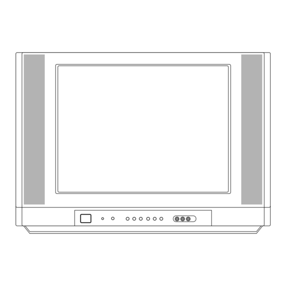
Page 6: Front Panel
Front panel VIDEO AUDIO MENU ON/OFF 2 3 4 1. MAIN POWER (ON/OFF) switches the set on or off. 2. POWER/STANDBY INDICATOR illuminates brightly when the set is in standby mode. dims when the set is switched on. 3. REMOTE CONTROL SENSOR Note : Only use the supplied remote control handset. -
Page 7: Specifications
SPECIFICATIONS Note : Specification and others are subject to change without notice for improvement. Scope 4) Specification and performance of each parts are followed each drawing and specification by part number in This specification can be applied to all the television related to accordance with BOM. - Page 8 Front Local Key Power, Vol( ), PR( ), MENU, OK 7EA/ Front Turbo-Picture, Sound Option Remocon LG Code (NEC) Channel Auto prog. System/ Storage/ Normal/ Turbo Manual Storage/ System/ Channel/ Fine/ Search/ Name Prog. edit Copy/ Move/ Delete/ Skip Favorite...
-
Page 9: Adjustment
(When adhering DY, use the electric driver of which turning force is lower than 10Kg/Cm) <Fig. 2> 3-2. Adjustment Preparation 1) Input LG standard signal into 75Ω antenna terminal (or <Fig. 2> PAL-B/G 05CH) 2) Connect the digital multi-meter to terminal(with Hole/ 5-2. - Page 10 (4) Dynamic Convergence (DYC) Adjustment (*In case there is excess RED color, adjust it using the VOLUME - key of the remote control until the RED color 1) Vertical Line Adjustment : Adjust by moving DY right and disappear.) left Color temperature : 12000°K 2) Horizontal Line Adjustment : Adjust by moving DY up X Coordinate : 270±8...
- Page 11 8. SUB-BRIGHTNESS Adjustment 11. Instrument setting data Prior to this adjustment, the White balance adjustment (automatic adjustment) should be finished. <TABLE 2> VIDEO IC EEPROM Speed Delay 8-1. Adjustment Preparation SLave ADD 1) Receive the PAL B/G 5CH signal into RF mode regardless of channel.
- Page 12 <TABLE 1> Adjustment Range Initial setting Remark Menu RF AGC Delay 0 ~ 63 Necessary VP 0 RF AGC 0 ~ 31 Necessary VP 1 H POS H PHASE Necessary VP 2 V POS V Shift (V POSI) 0 ~ 15 V SIZE Vertical Size 0 ~ 127...
- Page 13 Menu Adjustment Range Initial setting Remark VP 54 Y TH Y TH 0 ~ 3 Unnecessary VP 55 Y GAIN Y Gain 0 ~ 3 Unnecessary VP 56 R WIDTH R width 0 ~ 3 Unnecessary VP 57 R OFFSET R offset 0 ~ 3 Unnecessary...
-
Page 14: Printed Circuit Board
PRINTED CIRCUIT BOARD MAIN - 14 -... -
Page 15: Block Diagram
BLOCK DIAGRAM - 15 -... -
Page 16: Trouble Shooting
TROUBLE SHOOTING 1. TV FUNCTIONAL 2. TU / IF SECTION 3. VIDEO PROCESSING In case of influx NOISE - R/C is not operate Maneuver defectiveness Maneuver defectiveness Maneuver defectiveness - 16 -... - Page 17 4. SMPS PRIMARY SECTION 5. SMPS SECONDARY SECTION - 17 -...
- Page 18 6. VERTICAL SECTION 7. HORIZONTAL SECTION - 18 -...
- Page 19 8. SOUND PROCESSING SECTION 9. CPT DRIVE SECTION - 19 -...
-
Page 20: Exploded View
EXPLODED VIEW P801 - 20 -... -
Page 21: Exploded View Parts List
BUTTON, 21FB50 ABS PAKISTAN 3809V00323T Cover Assembly, RT-21FB55VE 1PHONE 8G068(407AF)SY-C/SKD 3809V00333M BACK COVER ASSEMBLY, 21FB5RL-TH DVD(1PHONE) MC059B 3809V00333P BACK COVER ASSEMBLY, 21FB5RB-TH 1PHONE SY-LGETH MONO MC059B 3809V00409C BACK COVER ASSEMBLY, RT-21FB50VE DVD(1PHONE) SY-PAKISTAN 68719MM659A PWB(PCB) ASSEMBLY,MAIN M.I MC059B 21FB5RB-TH NTWLLCT SY-TH 68719MM731A PCB Assembly,Main MAIN1 M.I MC059B 21FB5RG-TH NMILLCT 7W+7W AV/ST SY-TH... -
Page 22: Replacement Parts List
REPLACEMENT PARTS LIST For Capacitor & Resistors, the CC, CX, CK, CN : Ceramic RD : Carbon Film charactors at 2nd and 3rd digit CQ : Polyestor RS : Metal Oxide Film in the P/No. means as follows; CE : Electrolytic RN : Metal Film RF : Fusible LOCA. - Page 23 For Capacitor & Resistors, CC, CX, CK, CN : Ceramic RD : Carbon Film the charactors at 2nd and 3rd CQ : Polyestor RS : Metal Oxide Film digit in the P/No. means as CE : Electrolytic RN : Metal Film follows;...
- Page 24 For Capacitor & Resistors, CC, CX, CK, CN : Ceramic RD : Carbon Film the charactors at 2nd and 3rd CQ : Polyestor RS : Metal Oxide Film digit in the P/No. means as CE : Electrolytic RN : Metal Film follows;...
- Page 25 For Capacitor & Resistors, CC, CX, CK, CN : Ceramic RD : Carbon Film the charactors at 2nd and 3rd CQ : Polyestor RS : Metal Oxide Film digit in the P/No. means as CE : Electrolytic RN : Metal Film follows;...
- Page 26 For Capacitor & Resistors, CC, CX, CK, CN : Ceramic RD : Carbon Film the charactors at 2nd and 3rd CQ : Polyestor RS : Metal Oxide Film digit in the P/No. means as CE : Electrolytic RN : Metal Film follows;...
- Page 27 P/NO: 3854VA0196B - S1 2005.8.16...
- Page 28 SVC. SHEET : 3854V A0196B-S...
- Page 29 Mar., 2006 P/NO : 3828VD0235L Printed in Korea...
Need help?
Do you have a question about the 21FB5RB and is the answer not in the manual?
Questions and answers