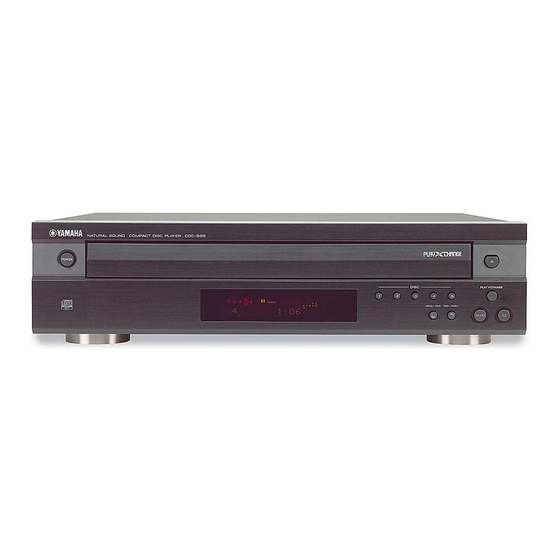
Yamaha CDC-585 Service Manual
Hide thumbs Also See for CDC-585:

Advertisement

QQ
3 7 63 1515 0
TE
L 13942296513
CONTENTS
TO SERVICE PERSONNEL ..................................... 1~2
STATICALLY SENSITIVE (ES) DEVICES ................... 3
FRONT PANELS ........................................................... 4
REAR PANELS ............................................................. 5
INTERNAL VIEW .......................................................... 6
DISASSEMBLY PROCEDURES .............................. 7~9
MAIN P.C.B. CHECK .................................................. 10
STANDARD OPERATION CHART ...................... 11~12
TEST MODE .......................................................... 13~15
www
このサービスマニュアルは、エコマーク認定の再生紙を使用しています。
.
This Service Manual uses recycled paper.
1 0 0 7 4 1
http://www.xiaoyu163.com
CDC-685/CDC-906
This manual has been provided for the use of authorized YAMAHA Retailers and their service personnel.
It has been assumed that basic service procedures inherent to the industry, and more specifically YAMAHA
Products, are already known and understood by the users, and have therefore not been restated.
WARNING:
IMPORTANT:
The data provided is believed to be accurate and applicable to the unit(s) indicated on the cover. The research,
engineering, and service departments of YAMAHA are continually striving to improve YAMAHA products.
Modifications are, therefore, inevitable and specifications are subject to change without notice or obligation to
retrofit. Should any discrepancy appear to exist, please contact the distributor's Service Division.
WARNING:
IMPORTANT:
x
ao
u163
y
i
http://www.xiaoyu163.com
CDC-585/CDC-506/CDC-685/CDC-906
2 9
8
COMPACT DISC PLAYER
SERVICE MANUAL
SERVICE MANUAL
IMPORTANT NOTICE
Failure to follow appropriate service and safety procedures when servicing this product may
result in personal injury, destruction of expensive components, and failure of the product to
perform as specified. For these reasons, we advise all YAMAHA product owners that any
Q Q
3
6 7
1 3
1 5
service required should be performed by an authorized YAMAHA Retailer or the appointed
service representative.
The presentation or sale of this manual to any individual or firm does not constitute authoriza-
tion, certification or recognition of any applicable technical capabilities, or establish a
principle-agent relationship of any form.
Static discharges can destroy expensive components. Discharge any static electricity your body
may have accumulated by grounding yourself to the ground buss in the unit (heavy gauge black
wires connect to this buss).
Turn the unit OFF during disassembly and part replacement. Recheck all work before you apply
power to the unit.
IC DATA ................................................................ 19~23
DISPLAY DATA .......................................................... 24
IC BLOCKS ........................................................... 25~26
PIN CONNECTION DIAGRAM ................................... 27
BLOCK DIAGRAM ................................................ 28~29
PRINTED CIRCUIT BOARD ................................. 30~37
CDC-585/CDC-506 SCHEMATIC DIAGRAM ...................... 38
CDC-685/CDC-906 SCHEMATIC DIAGRAM ...................... 39
PARTS LIST .......................................................... 40~54
GREASE APPLICATION DIAGRAM .......................... 55
REMOTE CONTROL TRANSMITTER ........................ 56
co
.
9 4
2 8
0 5
8
2 9
9 4
2 8
m
9 9
9 9

Advertisement

Table of Contents
loading

Summary of Contents for Yamaha CDC-585

  • Page 1: Table Of Contents

    SERVICE MANUAL IMPORTANT NOTICE This manual has been provided for the use of authorized YAMAHA Retailers and their service personnel. It has been assumed that basic service procedures inherent to the industry, and more specifically YAMAHA Products, are already known and understood by the users, and have therefore not been restated.
  • Page 2: To Service Personnel

    CDC-585/CDC-506/CDC-685/CDC-906 3 7 63 1515 0 TO SERVICE PERSONNEL AC LEAKAGE 1. Critical Components Information WALL EQUIPMENT T E S T E R O R Components having special characteristics are marked OUTLET UNDER TEST EQUIVALENT and must be replaced with parts having specifications equal to those originally installed.
  • Page 3 CDC-585/CDC-506/CDC-685/CDC-906 3 7 63 1515 0 PROTECTION OF EYES FROM LASER BEAM DURING SERVICING This set employs a laser. Therefore, be sure to carefully follow the instructions below when servicing. 1. Laser Diode Properties Material : GaAlAs Wavelength : 780 nm Emission Duration : Continuous : max.
  • Page 4: Prevention Of Electrostatic Discharge To

    CDC-585/CDC-506/CDC-685/CDC-906 3 7 63 1515 0 PREVENTION OF ELECTROSTATIC DISCHARGE (ESD) TO ELECTROSTATICALLY SENSITIVE (ES) DEVICES Some semiconductor (solid state) devices can be damaged easily by static electricity. Such components commonly are called Electrostatically Sensitive (ES) Devices. Examples of typical ES devices are integrated circuits and some field-effect transistors and semiconductor “chip”...
  • Page 5: Internal View

    CDC-585/CDC-506/CDC-685/CDC-906 3 7 63 1515 0 SPECIFICATIONS INTERNAL VIEW P.C.B. MAIN (2) AUDIO SECTION CLAMP ASS’Y Output Level (1kHz 0dB) 2.0±0.5V CM-230 UNIT (CDC-585/CDC-506) S/N Ratio 106dB CM-240 UNIT (CDC-685/CDC-906) Dynamic Range 96dB P.C.B. MAIN (1) Harmonic Distortion+Noise (1kHz) 0.003% TRAY ASS’Y...
  • Page 6 CDC-585/CDC-506/CDC-685/CDC-906 3 7 63 1515 0 DISASSEMBLY PROCEDURES (Remove parts in the order as numbered.) 1. Removal of Top Cover 4. Removal of Table a. Remove 4 screws ( q ) and also 3 screws ( w ) as a.
  • Page 7 5. Removal of CM-240 Unit 5-A.Removal of Front Panel Unit (CDC-685/CDC-906 only) (CDC-585/CDC-506 only) a. Remove 4 screws ( !0 ) as shown in Fig. 5. a. Remove CB200, CB301 and CB304. b. Remove connectors (CB202 & 410) and cables (CB1 b.
  • Page 8 CDC-585/CDC-506/CDC-685/CDC-906 3 7 63 1515 0 6. Removal of PU Mechanism Unit Operation Check Procedure a. Remove 2 screws ( !1 ) and then remove the PU q Disassembly Unit Ass'y as shown Fig. 6. 1) Remove the top cover.
  • Page 9: Main P.c.b. Check

    CDC-585/CDC-506/CDC-685/CDC-906 3 7 63 1515 0 MAIN P.C.B. CHECK Preparation before MAIN P.C.B. Check a. Remove the Top Cover. b. Remove the Tray Ass'y c. Remove 3 screws ( q ) on the Panel as shown in CAUTION : The ground point must be connected to Fig.
  • Page 10: Standard Operation Chart

    CDC-585/CDC-506/CDC-685/CDC-906 3 7 63 1515 0 STANDARD OPERATION CHART Press OPEN/CLOSE key. “OPEN” appears on the display. “TRV” signal is output until detection of LIMIT switch. Forced feed return operation. Proceeds to next step after detection of CLAMP switch. (SW400) Clamp down operation.
  • Page 11 CDC-585/CDC-506/CDC-685/CDC-906 3 7 63 1515 0 FOCUS GAIN ADJ. TRACKING GAIN ADJ. *TOC READ ~ Data fetch cycle ~ TRACK No. “1” is searched. : MUTE OFF = “L” → “H”, “0:00” appears on the display. After searching the beginning, MUTE is cancelled.
  • Page 12: Test Mode

    CDC-585/CDC-506/CDC-685/CDC-906 3 7 63 1515 0 TEST MODE Starting TEST mode Test mode is started when the power is turned on while the “PLAY/PAUSE” and “STOP” keys on the panel are simultaneously pressed and held. When the test mode is started, all the displays light up for about 1 second. ("TEST" on display) NOTE : To fully operate all test modes the remote control must be used.
  • Page 13 CDC-585/CDC-506/CDC-685/CDC-906 3 7 63 1515 0 Function List of Remote Control Transmitter CUSTOM CODE = (79)x FUNCTION CODE MODE Traverse stop OPEN/CLOSE Tray open/close PLAY (FOON, TRON, TVON (FEON), SPON) PLAY Backward traverse move. (If inner SW turns on, traverse is stopped.)
  • Page 14 CDC-585/CDC-506/CDC-685/CDC-906 3 7 63 1515 0 (Note 2) Checks FL display. L 13942296513 DIMMER TEXT/TIME u163 CDC-685/CDC-906 http://www.xiaoyu163.com...
  • Page 15: Error Message

    The operation mode turns to the mode allowing the display of messages. The unit hold the latest error message in EEPROM. So even if stopped with no error, the unit can display the latest error massage with same operation. (Except for CDC-585/CDC-506, which have no EEPROM. ) Error Messages List * Meaning of each state (“X”) :...
  • Page 16 CDC-585/CDC-506/CDC-685/CDC-906 3 7 63 1515 0 X8 ....Error code Focus drops. 2) Troubleshooting from System Malfunctions. a) Tray fails to come out/go in. Check by using Is disc dirty or Poor mechanism operation. another disc. Tray starts to scratched? Wire caught.
  • Page 17 CDC-585/CDC-506/CDC-685/CDC-906 3 7 63 1515 0 d) Sound skips. c) Operates as if no disc loaded. (Time display fails to advance properly) (although loaded) Does table Is disc dirty, Check by using a Poor table rotation. rotate properly? scratched or known good disc.
  • Page 18: Ic Data

    CDC-585/CDC-506/CDC-685/CDC-906 3 7 63 1515 0 IC DATA µ IC301 : PD78P076GF-3BA µ 8bit -COM P120/RTP0 P66/WAIT P121/RTP1 P65/WR P122/RTP2 P64/RD P123/RTP3 P124/RTP4 P125/RTP5 P126/RTP6 P127/RTP7 P57/A15 P56/A14 P55/A13 P54/A12 P53/A11 XT1/P07 P52/A10 RESET P51/A9 P00/INTP0/TI00 P50/A8 P01/INTP/TI01 P47/AD7...
  • Page 19 CDC-585/CDC-506/CDC-685/CDC-906 3 7 63 1515 0 µ IC301 : PD78P076GF-3BA µ 8bit -COM Function Port Name P13/ANI3 N.C. P14/ANI4 EEPROM P15/ANI5 EEPROM CLOCK P16/ANI6 N.C. P17/ANI7 AVSS AVSS P130/ANO0 N.C. AN8849 gain control. P131/ANO1 GCTRL AVREF1 P70/S12/RXD SUBQ Serial I/F input (SUBQ) P71/SO2/TXD Status signal input from MN35511.
  • Page 20 CDC-585/CDC-506/CDC-685/CDC-906 3 7 63 1515 0 µ IC301 : PD78P076GF-3BA µ 8bit -COM Function Port Name P67/ASTB N.C. P100/TI5/TO5 TBL-L Table couterclockwise rotate signal output. P101/TI6/TO6 TBL-R Table clockwise rotate signal output. P102 N.C. N.C. P103 P30/TO0 CLOSE Tray close signal output.
  • Page 21 CDC-585/CDC-506/CDC-685/CDC-906 3 7 63 1515 0 IC3 : MN35511AL Signal Processor & Controller Function Pin No. Name BCLK Bit clock output for SR DATA LRCK L/R identification signal output Serial data output SRDATA DVDD1 Power supply for digital circuit...
  • Page 22 CDC-585/CDC-506/CDC-685/CDC-906 3 7 63 1515 0 IC3 : MN35511AL Signal Processor & Controller Pin No. Name Function DSLF Loop filter terminal for DSL PLLF Loop filter terminal for PLL VCOF Loop filter terminal for VCO (+5) AVDD2 Power supply for analog circuit (for AD of DSL, PLL, DA output blocks)
  • Page 23: Display Data

    CDC-585/CDC-506/CDC-685/CDC-906 3 7 63 1515 0 DISPLAY DATA (V3008400) &6 V300 : 15-ST-20G PATTERN AREA • PIN CONNECTION NOTE 1) F1, F2 ..Filament 4) P1~P18 ..Datum Line 2) NP ..... No pin 5) 1G~15G ..Grid 3) NX ..... No extend pin 6) IC ....
  • Page 24: Ic Blocks

    CDC-585/CDC-506/CDC-685/CDC-906 3 7 63 1515 0 IC BLOCKS IC1 : AN8882SB IC2 : AN4801SB Digital Servo Head Amp 4-Channel BTL Driver STAND VREF-IN STAND BY VREF-OUT SS. GND DETECTION RF-AGC N. C. STAND BY CBDO GAIN 1 GAIN 4...
  • Page 25: Pin Connection Diagram

    CDC-585/CDC-506/CDC-685/CDC-906 3 7 6 3 1 5 1 5 0 PIN CONNECTION DIAGRAM IC401 : LA6510 IC302 : S-24C01ADP 1SS133 2SA933S (Q,R) 2SB544 (E,F,G) 2SA1708(S,T) 22SB1565 (E, F) MN35511 Dual Power Operational Amp 1N4002S 2SC1740S (R,S) 2SC2878 (A, B)
  • Page 26: Block Diagram

    CDC-585/CDC-506/CDC-685/CDC-906 3 7 6 3 1 5 1 5 0 BLOCK DIAGRAM PICK UP IC101 IC101 OUT L Q101 Q103 HEAD LINE OUT IC102 CONTROL Q102 Q104 IC102 AN8882SB OUT R LASER LD ON MN35511 MUTE IC105 VREF CONTROL...
  • Page 27: Cdc-585/Cdc-506 Schematic Diagram

    CDC-585/CDC-506/CDC-685/CDC-906 CDC-585/CDC-506/CDC-685/CDC-906 CDC-585/CDC-506 SCHEMATIC DIAGRAM CDC-585/CDC-506 SCHEMATIC DIAGRAM TEKTRONIX 2232 CD HEAD AMP V1= 0.00 V TRIG1= -0.1 V T= 0.0ns SAVE WITH DAC MUTING -5.1 -5.0 -5.0 SAMPLE 50ns -5.0 -5.0 -5.1 TEKTRONIX 2232 V1= 0.00 V TRIG1= -0.2 V T= 0.000µs...
  • Page 28: Cdc-685/Cdc-906 Schematic Diagram

    CDC-585/CDC-506/CDC-685/CDC-906 CDC-685/CDC-906 SCHEMATIC DIAGRAM TEKTRONIX 2232 CD HEAD AMP V1= 0.00 V TRIG1= -0.1 V T= 0.0ns SAVE WITH DAC MUTING -5.1 -5.0 -5.0 SAMPLE 50ns -5.0 -5.0 -5.1 TEKTRONIX 2232 V1= 0.00 V TRIG1= -0.2 V T= 0.000µs SAVE ACT.
  • Page 29 CDC-585/CDC-506/CDC-685/CDC-906 3 7 63 1515 0 FRONT PANELS CDC-585/CDC-506 CDC-685/CDC-906 L 13942296513 REMOTE CONTROL TRANSMITTER CDC-585/CDC-506 CDC-685/CDC-906 CAUTION FOR TRANSPORTING THIS UNIT When transporting this unit, first remove all discs from the disc tray and close the tray by pressing the OPEN/CLOSE but-...
  • Page 30 CDC-585/CDC-506/CDC-685/CDC-906 3 7 63 1515 0 REAR PANELS U, C models CDC-685 ONLY R model L 13942296513 A model CDC-685 ONLY B, G model u163 http://www.xiaoyu163.com...
  • Page 31 CDC-585/CDC-506/CDC-685/CDC-906 3 7 6 3 1 5 1 5 0 PRINTED CIRCUIT BOARD (Foil side) CDC-685/CDC-509 P. C. B. MAIN ( 2 ) TEKTRONIX 2232 V1= 0.00 V TRIG1= -0.1 V T= 0.0ns SAVE LINE OUT CDC-685/CDC-509 P. C. B. MAIN ( 1 )
  • Page 32: Printed Circuit Board

    CDC-585/CDC-506/CDC-685/CDC-906 3 7 6 3 1 5 1 5 0 PRINTED CIRCUIT BOARD (Foil side) P. C. B. MAIN ( 3 ) CDC-685/CDC-906 only CDC-685/CDC-906 only PROG FROM : MAIN (1) CDC-685/CDC-906 P. C. B. MAIN ( 7 ) P.
  • Page 33 CDC-585/CDC-506/CDC-685/CDC-906 3 7 6 3 1 5 1 5 0 PRINTED CIRCUIT BOARD (Foil side) P. C. B. MAIN ( 5 ) P. C. B. CM ( 1 ) P. C. B. CM ( 2 ) FROM : MAIN (1)
  • Page 34 CDC-585/CDC-506/CDC-685/CDC-906 3 7 6 3 1 5 1 5 0 PRINTED CIRCUIT BOARD (Foil side) CDC-585/CDC-506 P. C. B. MAIN ( 2 ) TEKTRONIX 2232 V1= 0.00 V TRIG1= -0.1 V T= 0.0ns SAVE LINE OUT CDC-585/CDC-506 P. C. B. MAIN ( 1 )
  • Page 35 CDC-585/CDC-506/CDC-685/CDC-906 3 7 6 3 1 5 1 5 0 PRINTED CIRCUIT BOARD (Foil side) P. C. B. MAIN ( 3 ) CDC-685/CDC-906 only CDC-685/CDC-906 only PROG FROM : MAIN (1) CDC-685/CDC-906 P. C. B. MAIN ( 7 ) P.
  • Page 36 CDC-585/CDC-506/CDC-685/CDC-906 3 7 6 3 1 5 1 5 0 PRINTED CIRCUIT BOARD (Foil side) P. C. B. MAIN ( 5 ) P. C. B. CM ( 1 ) P. C. B. CM ( 2 ) FROM : MAIN (1)
  • Page 37: Parts List

    CDC-585/CDC-506/CDC-685/CDC-906 WARNING PARTS LIST Components having special characteristics are marked Z and must be 3 7 63 1515 0 replaced with parts having specifications equal to those originally installed. ELECTRICAL PARTS Carbon resistors (1/6W or 1/4W) are not included in the ELECTRICAL PARTS List.
  • Page 38 CDC-585/CDC-506/CDC-685/CDC-906 3 7 63 1515 0 CDC-585/CDC-506 P.C.B. MAIN Schm Schm Ref. PART NO. Description Ref. PART NO. Description V6745000 P.C.B. MAIN(UC) VJ599100 C.CE.TUBLR 0.1uF V6745300 P.C.B. MAIN(R) VA761400 C.CE 47pF V6745400 P.C.B. MAIN(A) VJ599100 C.CE.TUBLR 0.1uF V6794000 P.C.B.
  • Page 39 CDC-585/CDC-506/CDC-685/CDC-906 3 7 63 1515 0 CDC-585/CDC-506 P.C.B. MAIN Schm Schm Ref. PART NO. Description Ref. PART NO. Description C308 VJ599100 C.CE.TUBLR 0.1uF Q200 iA093320 TR 2SA933S Q,R C309 VJ599100 C.CE.TUBLR 0.1uF Q201 VS883300 TR 2SB1565 E,F C404 VG288100 C.EL...
  • Page 40 CDC-585/CDC-506/CDC-685/CDC-906 3 7 63 1515 0 CDC-685/CDC-906 P.C.B. MAIN Schm Schm Ref. PART NO. Description Ref. PART NO. Description V6727100 P.C.B. MAIN(UC) VA761400 C.CE 47pF V6727700 P.C.B. MAIN(R) VJ599100 C.CE.TUBLR 0.1uF V6727800 P.C.B. MAIN(A) VA761400 C.CE 47pF V6727900 P.C.B.
  • Page 41 CDC-585/CDC-506/CDC-685/CDC-906 3 7 6 3 1 5 1 5 0 CDC-685/CDC-906 P.C.B. MAIN CDC-685/CDC-906 P.C.B. MAIN P.C.B. CM Schm Schm Schm Schm Ref. PART NO. Description Ref. PART NO. Description Ref. PART NO. Description Ref. PART NO. Description C218 VS741700 C.CE.SAFTY 0.01uF...
  • Page 42 CDC-585/CDC-506/CDC-685/CDC-906 3 7 6 3 1 5 1 5 0 CDC-585/CDC-506 EXPLODED VIEW MECHANICAL PARTS (CDC-585/CDC-506) Ref. PART NO. Description Remarks Markets * 3-3 MF122300 FLEXIBLE FLAT CABLE 22P 300mm P=1.25 * 3-11 V6401800 FRONT PANEL CDC-506GP * 3-11...
  • Page 43 CDC-585/CDC-506/CDC-685/CDC-906 3 7 63 1515 0 Ref. PART NO. Description Remarks Markets * 22 V6403400 REAR PANEL CDC-506GP * 23 V7354300 TOP COVER VQ780300 LEG D60xH16 CDC-585BL VQ982800 LEG D60xH16 CDC-506GP * 26 V6638900 LID CDC-585BL * 26 V6639100 LID...
  • Page 44 CDC-585/CDC-506/CDC-685/CDC-906 3 7 63 1515 0 CDC-685/CDC-906 EXPLODED VIEW 7-20 6-10 7-20 200-1 7-13 7-11 7-11 5-10 7-12 7-12 7-10 R model 5-10 L 13942296513 5-10 CM-240 Unit 3-30 3-21 3-30 3-30 3-15 3-30 3-13 3-30 3-20 3-12 3-11...
  • Page 45 CDC-585/CDC-506/CDC-685/CDC-906 3 7 6 3 1 5 1 5 0 MECHANICAL PARTS (CDC-685/CDC-906) Ref. Ref. PART NO. Description Remarks Markets PART NO. Description Remarks Markets * 13 VN363600 POWER CORD ASS'Y * 3-3 MF122300 FLEXIBLE FLAT CABLE 22P 300mm P=1.25...
  • Page 46 CDC-585/CDC-506/CDC-685/CDC-906 3 7 6 3 1 5 1 5 0 EXPLODED VIEW (CM-230/CM-240 Unit) MECHANICAL PARTS (CM-230/CM-240 Unit) Ref. PART NO. Description Remarks Markets CM-230 + ( ) = CM-240 V3172600 P.C.B. ASS'Y CM-230,CM-240 V6660800 FERRITE CORE F5 T19x10x10...
  • Page 47 CDC-585/CDC-506/CDC-685/CDC-906 3 7 63 1515 0 EXPLODED VIEW (PU Mecha. Unit) Note : Neither the pick-up head nor the spindle motor is available independently because they are factory-adjusted for the optimum level after assembly. If the pick-up head or the spindle motor must be replaced, be sure to replace them together as a unit.
  • Page 48: Grease Application Diagram

    CDC-585/CDC-506/CDC-685/CDC-906 3 7 63 1515 0 GREASE APPLICATION DIAGRAM (PU Mechanism) Apply the grease Molykote PG-663 (P/No. AAX01170) PG-663 PG-663 L 13942296513 PG-663 PG-663 u163 http://www.xiaoyu163.com...
  • Page 49: Remote Control Transmitter

    CDC-585/CDC-506/CDC-685/CDC-906 3 7 63 1515 0 REMOTE CONTROL TRANSMITTER SCHEMATIC DIAGRAM U1 JT7060-1A KI/06 KI/05 KI/07 KI/04 DISC REPEAT DISC SKIP SCAN KI/03 KI/02 OPEN/ CLEAR STOP CLOSE IR-LED RESET KI/01 OUTPUT PLAY TEXT/TIME SEARCH LEVEL+ KI/00 Ω 2SD1781K...
  • Page 50: Parts List For Carbon Resistors

    CDC-585/CDC-506/CDC-685/CDC-906 3 7 63 1515 0 Parts List for Carbon Resistors 1/4W Type Part No. 1/6W Type Part No. 1/6W Type Part No. Value Value 1/4W Type Part No. 1.0 Ω 3100 3100 7100 10 kΩ 7100 HJ35 HF85...

This manual is also suitable for:

Cdc-685Cdc-506Cdc-906

Table of Contents