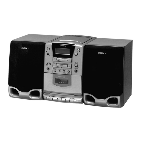
Sony PMC-222V Service Manual
Personal component system
Hide thumbs
Also See for PMC-222V:
- Operating instructions manual (40 pages) ,
- Service manual (58 pages)
Advertisement
Table of Contents
SERVICE MANUAL
Ver 1.0 1998.05
CD player section
System
Compact disk digital audio/video system
Laser diode properties
Material : GaAlAs
Wave length:780 nm
Emission duration : Continuous
Laser output : Less than 44.6 µW
(This output is the value measured at a distance of about
200 mm from the objective lens surface on the optical pick-
up block with 7 mm aperture.)
Spindle speed
200r/min (rpm) to 500 r/min (rpm) (CLV)
Number of channels
2
Frequency response
20 – 20,000Hz + 1/–2dB
Wow and flutter
Below measurable limit
Color system format
NTSC, PAL
Radio section
Frequency range
FM : 87.6 – 108 MHz
AM : 531 – 1,602 kHz
Aerials
FM : Wire aerial
AM : External aerial
Cassette-corder section
Recording system
4 -track 2 channel stereo
Fast winding time
Approx. 120 s (sec.) with Sony cassette C-60
Frequency response
TYPE I (normal) : 80 – 14,000 Hz
TYPE II (high position) : 80 – 15,000Hz
General
Full range : 10 cm (4 in.) dia., 6 Ω, cone type Tweeter :
Speaker
4
2cm (
/
in.) dia.
5
Inputs
Mixing microphone input jack (minijack):
Sensitivity 2.5mV
For 16 – 68 Ω impedance headphones
MICROFILM
PMC-222V
Model Name Using Similar Mechanism
CD
CD Mechanism Type
Section
Optical Pick-up Name
Tape deck
Model Name Using Similar Mechanism
Section
Tape Transport Mechanism Type
SPECIFICATIONS
Outputs
Maximum power output 30W + 30W
Power requirements
Power consumption
Dimensions (incl. projecting parts and controls)
Mass
Supplied accessories
Design and specifications are subject to change without notice.
PERSONAL COMPONENT SYSTEM
E Model
Ï
CFD-V34L
KSM-213CDM/C2NP
KSS-213C/Q-RP
NEW
MF-PMC212
Headphones jack (stereo minijack)
For 16 – 64 Ω impedance headphones
Video output (phono jack)
Output level 1Vp-p at 75Ω
Recommended load impedance over 75Ω
For CD radio cassette-corder
230V AC, 50Hz
For remote control:
3V DC, 2R6 (size AA) batteries
AC 55W
Player: Approx. 160 × 237 × 292.5 mm (w/h/d)
× 9
× 11
3
3
5
(6
/
/
/
inches)
8
8
8
Speaker: Approx. 150 × 230 × 240 mm (w/h/d)
(6 × 9
× 8
1
1
/
/
inches)
8
2
Player: Approx. 4.9 kg (10 lb 13 oz)
Speaker: Approx. 2.2 kg (4 lb 14 oz)
Remote control (1)
AM loop aerial (1)
Video cord (1)
Advertisement
Table of Contents

Subscribe to Our Youtube Channel
Related Manuals for Sony PMC-222V


Summary of Contents for Sony PMC-222V
-
Page 1: Specifications
Design and specifications are subject to change without notice. Recording system 4 -track 2 channel stereo Fast winding time Approx. 120 s (sec.) with Sony cassette C-60 Frequency response TYPE I (normal) : 80 – 14,000 Hz TYPE II (high position) : 80 – 15,000Hz General Full range : 10 cm (4 in.) dia., 6 Ω, cone type Tweeter :... - Page 2 PMC-222V 5-2. BLOCK DIAGRAM — TUNER, TAPE, AMP SECTION — 5-3. CIRCUIT BOARDS LOCATION REGULATOR board CD MOTOR board POWER board V-JACK board CD board MAIN board LAMP board CD/VIDEO CD SECTION CONTROL board HEADPHONE board KEY board VCD board...
- Page 3 PMC-222V 5-5. SCHEMATIC DIAGRAM — CD, SYSTEM CONTROL SECTION — • Waveform E-F BALANCE TRACKING GAIN (Page 57) FOCUS GAIN (Page 45) Note on Schematic Diagram: • All capacitors are in µF unless otherwise noted. pF: µµF 50 WV or less are not indicated except for electrolytics and tantalums.
- Page 4 PMC-222V 5-6. SCHEMATIC DIAGRAM — TUNER, TAPE, AMP SECTION — • Waveform Q306 Note on Schematic Diagram: • All capacitors are in µF unless otherwise noted. pF: µµF 50 WV or less are not indicated except for electrolytics and tantalums.
- Page 5 PMC-222V 5-9. SCHEMATIC DIAGRAM — VIDEO CD SECTION — (Page 40) (Page 45) Note on Schematic Diagram: • All capacitors are in µF unless otherwise noted. pF: µµF 50 WV or less are not indicated except for electrolytics and tantalums.
- Page 6 5-10. IC BLOCK DIAGRAMS TA2008AN FM MPX BUFF BUFF BUFF BUFF AM/FM ST/MONO 1/801V LEVEL MUTE BU2614 IC306 TDA7265 IC304 TDA7319 IC308 CD4052BCN — 60 —...
- Page 7 IC701 CXA1782BQ – LEVELS 24 SENS – MIRR RF IV AMP1 DFCT 23 C. OUT – 22 XRST RF IV AMP2 21 DATA FE BIAS • IIL DATA RESISTOR • INPUT SHIFT RESISTOR • ADDRESS DECODER 20 XLT • OUTPUT DECODER 19 CLK –...
- Page 8 IC702 CXD2500BQ U1009 SM5877AM ATCK ATTENUATION COUNTER MUTE MODE FILTER PROCESSOR & DEEN ATTENUATION PROCESSOR RSTN NOISE SHAPER TIMING DVSS PROCESSOR BLOCK CONTROL BCKI INPUT INTERFACE XVSS DVDD PWN DATA LRCI PRODUCE BLOCK TSTN XVDD MUTE AVDDR AVDDL AVSS IC703 BA5930FP —...
Need help?
Do you have a question about the PMC-222V and is the answer not in the manual?
Questions and answers