Technics SJ-MD100 Service Manual
Hide thumbs
Also See for SJ-MD100:
- Service manual (60 pages) ,
- Operating instructions manual (33 pages) ,
- Operating instructions manual (32 pages)
Advertisement
Quick Links
Download this manual
See also:
Service Manual
$ This document is supplementary to the
following Service Manual:
Model No.
SJ-MD100
$ Purpose
Supplement for technical information about MD.
$ Contents
1. Measuring instruments and special tools
Test Disc
Extension Cable Kit
Laser Power Meter
2. Basic Knowledge of MD
3. Operating Procedures
4. Troubleshooting Guide for MD Servo Circuit
This service information is designed for experienced repair technicians only and is not designed for use by the general public. It does not
contain warnings or cautions to advise non-technical individuals of potential dangers in attempting to service a product.
Products powered by electricity should be serviced or repaired only by experienced professional technicians. Any attempt to service or
repair the product or products dealt with in this service information by anyone else could result in serious injury or death.
Area Code
Order No.
(E) (EB) (EG)
MB9902001C2
O ROM
Part No.: RFKV0006
O ROM
Part No.: RFKV0014
O Extension Cable Kit
Part No.: RFKZJMD100EK
O Laser Power Meter
Model No.: LE8010
Made by Laser Electric
WARNING
©
All rights reserved. Unauthorized copying
and distribution is a violation of law.
ORDER NO. AD9903069S2
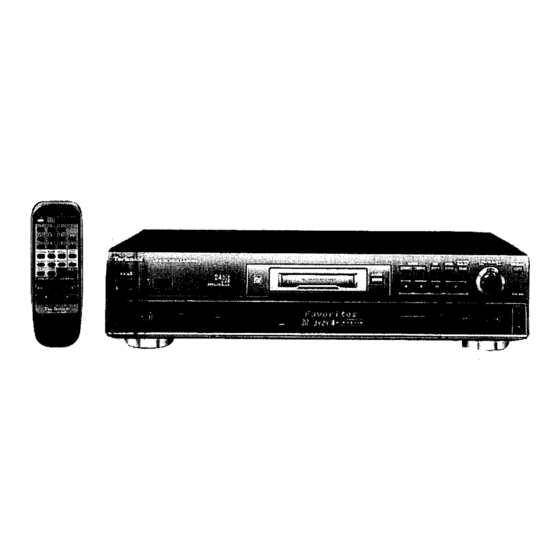
Minidisc Deck
SJ-MD100
Colour
(K) ........ Black Type
Areas
(E) ........ Europe.
(EB) ...... Great Britain.
(EG) ...... Germany.
1999 Matsushita Electric Industrial Co., Ltd.
Advertisement

Related Manuals for Technics SJ-MD100


Summary of Contents for Technics SJ-MD100
- Page 1 ORDER NO. AD9903069S2 Minidisc Deck SJ-MD100 Colour (K) ..Black Type Areas $ This document is supplementary to the (E) ..Europe. (EB) ..Great Britain. following Service Manual: (EG) ..Germany. Model No. Area Code Order No. SJ-MD100 (E) (EB) (EG)
- Page 2 SJ-MD100 $ Basic Knowledge of MD T Definition of an MD and the types of MDs U What is an MD? Y "MD" stands for "mini disc". Y Similar to a music CD, an MD is also a small disc capable of recording and playing back digital sound.
- Page 3 SJ-MD100 Recording on a magnet optic disc U Can be recorded and played Y By using a magnet optic disc, digital signals can be recorded and played back over and over again. back repeatedly. U Recording principle Y To record on a magnet optic disc, a laser beams momentarily heats "pin spots" on the magnetic film on the back of the disc and a magnetic field is applied from the other side of the disc.
- Page 4 SJ-MD100 Playback of a recordable MD U Playback of a recordable Y Because the signals on a magnet optic disc are recorded vertically as north-south and south-north magnetism, the north and south magnetic poles appear on the surface of the disc's magnetic film. These signals are played back utilizing a phenomenon called the "Kerr effect"...
- Page 5 SJ-MD100 Rewriting action of a magnet optic disc U MD rewriting process Y The signals recorded on an MD are rewritten using a new process called “magnetic field modulation overwriting”*. Y In this process, a laser beam spot of about 5 mW is focused on the location on the disc to be rewritten, heating that location to the Curie temperature (180pC) and thus canceling the magnetization.
- Page 6 SJ-MD100 Random access on a recordable MD U R a n d o m a c c e s s o n a Y With a disc, high-speed random access is possible, something which is not possible with a tape.
- Page 7 SJ-MD100 ATRAC signal compression technology U What does the word ATRAC Y “ATRAC” (adaptive transform acoustic coding) is the name given to the signal compression technology that is one mean? of the most important technologies used in the MD system. The principles of this technology are extremely complex, so here we will only explain the basic concept.
- Page 8 SJ-MD100 Composition of an MD system U Development of 6 LSIs Y The figure below shows the composition of an MD system. An MD system uses six LSIs that were specifically developed for MD. The following is a description of the functions of those six LSIs.
- Page 9 SJ-MD100 $Operating Procedures Play P1. To read the signals recorded on the disc, the laser beam emitted by the laser diode (LD) strikes the disc and is reflected back and detected by the photodetector (PD). T For a pre-mastered disc, similar to a CD, the signals are recorded as pits on the surface of the disc, and the signals are detected by the amount of light reflected when the laser beams strikes the pits.
-
Page 10: Block Diagram
SJ-MD100 Block Diagram DRAM(4Mbit) IC72 MNV4400 Magnetic Magnetic head Clock head Drive Q10,11 16.9334MHz 0.9V DISC 0.45V MD LSI 0.5¨s. 0.1V/DIV. MN66616 0.5¨s. 50mV/DIV. mod/demo Traverse Optical Spindle ATRAC encoder / IC1 AN8772 motor pickup motor decoder Servo signal processor... - Page 11 SJ-MD100 $Troubleshooting Guide for MD Servo Circuit Switch power ON with no MD loaded. Does player enter self-check mode? *1 3.3V *1 : See Srevice Manual page 35. 3.3V Is CN4 power supply line OK? Set to read power adjustment mode. *2 Check power supply *2 : See Srevice Manual page 69.
- Page 12 SJ-MD100 Is output voltage of IC1 pin 37 (TP35) approx. 1.3 V *1 Is voltage of IC1 pin 36 2.6 V? *1 Is voltage Is voltage on both sides of R5 Faulty IC9 of IC9 pin 3 at least 0.025 V? 2.6 V?
- Page 13 SJ-MD100 ROM/RAM Operation Can ROM disc be inserted correctly? H = 3.3V L = 0V Does CN4 D i s c t r a y pin 18 change from IC10 STOP/PLAY O P E N e LOAD OPEN SW0 (S3) "H"...
- Page 14 SJ-MD100 Is TOC read and disc data displayed? Is there output from IC1 pins 11 (TP55) and 16 (TP57)? *1 See Service Manual page 27 for measurements of IC1. waveform of IC1 pin 11 be adjusted so that it is approx. symmetrical with a level of 1.5 Vp-p?
- Page 15 SJ-MD100 16.9344MHz Is playback 10.9344MHz possible? Is playback sound 3.3V Is output of IC3 pins 61 ~ 65 OK during playback? 3.3V Press eject key and remove ROM disc. – Faulty audio circuit Faulty IC3 Can RAM disc be inserted?
- Page 16 SJ-MD100 Traverse Operation Remains at outer track. Traverse operation Remains at inner track. Is IC10 pin 12 approx. 0 V? Faulty (shorted) traverse detection switch S8 Is IC10 pin 12 approx. 3.3 V? 1.65V Is output of IC3 pin 20 OK?
Need help?
Do you have a question about the SJ-MD100 and is the answer not in the manual?
Questions and answers