Table of Contents
Advertisement
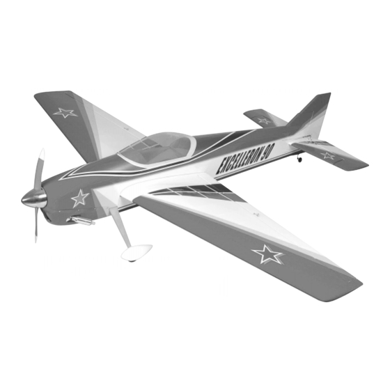
INSTRUCTIONS FOR FINAL ASSEMBLY
The Sportsman Aviation Excelleron 90 ARF is distributed
exclusively by Global Hobby Distributors
18480 Bandilier Circle, Fountain Valley, CA 92708
All contents copyright © 2004, Global Hobby
Distributors Version V1.0b February 2004
Kit Product Number 127565
IMPORTANT
The Sportsman Aviation Excelleron 90 ARF is not intended for inexperienced pilots. It is in no way a
trainer. If you are not comfortable flying aerobatic aircraft, we strongly suggest returning the Excelleron 90 ARF (brand
new, in the box with all original packaging and your dated sales receipt) to the place of purchase.
Specifications:
Wing Span: 66.5 Inches
Wing Area: 865 Square Inches
Length: 67.5 Inches
Weight RTF: 8 - 8.5 Pounds
Wing Loading: 20 - 22 Ounces Per Square Foot
Functions: Ailerons, Elevator, Rudder & Throttle
Engine Required: .91 - 1.10 Two-Stroke
.91 - 1.20 Four-Stroke
Radio Required: 4Ch or More w/5 Ball Bearing Servos
The Excelleron 90 ARF Requires the Use of High-Torque
Servos. Please See Page # 4 For More Information.
1
Advertisement
Table of Contents

Related Manuals for Sportsman Aviation Excelleron 90


Summary of Contents for Sportsman Aviation Excelleron 90
- Page 1 Servos. Please See Page # 4 For More Information. IMPORTANT The Sportsman Aviation Excelleron 90 ARF is not intended for inexperienced pilots. It is in no way a trainer. If you are not comfortable flying aerobatic aircraft, we strongly suggest returning the Excelleron 90 ARF (brand...
-
Page 2: Table Of Contents
OUR GUARANTEE Sportsman Aviation guarantees this kit to be free from defects in both material and workmanship at the date of purchase. This does not cover any component parts damaged by use, misuse or modification. In no case shall Sportsman Aviation's liability exceed the original cost of the purchased kit. -
Page 3: Introduction
Sportsman Aviation ARF product owners and the Sportsman Aviation ARF support staff. This is a great place to learn about new Sportsman Aviation ARF products, get help and suggestions for your current Sportsman Aviation ARF products or just simply hang out and chat with people that share your same interests. -
Page 4: Section 1: Our Recommendations
What Engine Should I Use? The Excelleron 90 ARF will fly well with a variety of different engines. The airplane is designed to be flown with .91 - 1.10 size two-stroke engines or .91 - 1.20 size four-stroke engines. Engines in the lower end of the size range will fly the airplane adequately, but the airplane really does perform best with engines in the higher end of the size range. -
Page 5: Section 2: Tools And Supplies Required
SECTION 2: TOOLS AND SUPPLIES REQUIRED The tools and supplies listed below will be necessary to finish the assembly of your Sportsman Aviation Excelleron 90 ARF. We suggest having these items on hand before beginning assembly. Kwik Bond Thin C/A # 887500... - Page 6 KIT CONTENTS, CONTINUED..AILERON CONTROL SYSTEM FUEL TANK ASSEMBLY (2) 7-1/2" Threaded Wires (1) 420cc Fuel Tank (2) Threaded Nylon Control Horn Mounts (1) Large Diameter Metal Plate (2) Nylon Control Horn Backplates (1) Small Diameter Metal Plate (2) Nylon Adjustable Control Horns (1) Rubber Stopper (6) M2 x 25mm Machine Screws (1) Fuel Pick-Up "Clunk"...
-
Page 7: Section 4: Replacement Parts
SECTION 4: REPLACEMENT PARTS We stock a complete line of replacement parts for your Sportsman Aviation Excelleron 90 ARF. Listed below are the replacement parts that are available along with their respective part numbers for easy ordering convenience. We suggest ordering directly from your local dealer. -
Page 8: Section 6: Wing Assembly
SECTION 6: WING ASSEMBLY YOU'LL NEED THE FOLLOWING PARTS FROM THE KIT: (1) Right Wing Panel w/Aileron (2) Molded Aileron Servo Fairings (1) Hardwood Wing Joiner (1) Left Wing Panel w/Aileron (8) Steel-Pinned Hinges (8) M2 x 6mm Wood Screws YOU'LL NEED THE FOLLOWING TOOLS AND SUPPLIES: Kwik Bond 5 Minute Epoxy Pencil... - Page 9 Mix a small quantity of 5 minute epoxy and carefully glue each of the four hinges into only the aileron for now. Make sure that the hinges' pivot point is straight and flush with the leading edge of the aileron, then remove any excess epoxy, using a paper towel and rubbing alcohol.
- Page 10 After installing the aileron servo, position one molded servo fairing over the servo, making sure that the predrilled hole in the servo fairing is centered over the servo output shaft. When satisfied with the alignment, hold the servo fairing in place, using a couple of pieces of masking tape.
- Page 11 While holding the two wing panels together firmly, make sure that both wing panels are lined up at both the leading and trailing edges, then look carefully at the center-section joint: the wing panels should fit together tightly with few or no gaps in the joint.
-
Page 12: Section 7: Belly Pan Installation
SECTION 7: BELLY PAN INSTALLATION YOU'LL NEED THE FOLLOWING PARTS FROM THE KIT: (2) M4 x 40mm Socket-Cap Screws (1) Fuselage (1) Belly Pan (2) M4 Flat Washers (2) 4mm Rubber Grommets (1) Plywood Wing-Screw Doubler YOU'LL NEED THE FOLLOWING TOOLS AND SUPPLIES: Wilhold Silicon Sealant 220 Grit Sandpaper w/Sanding Block 3mm Hex Wrench... - Page 13 With the wing installed onto the fuselage, position the belly pan onto the wing. When lined up properly, the sides and bottom of the belly pan should be even with the sides and bottom of the fuselage, and there should be few or no gaps between the base of the belly pan and the wing.
-
Page 14: Section 8: Stabilizer Installation
SECTION 8: STABILIZER INSTALLATION YOU'LL NEED THE FOLLOWING PARTS FROM THE KIT: (1) Horizontal Stabilizer w/Elevator Halves (1) Wheel Collar w/Grub Screw (1) Vertical Stabilizer w/Rudder (2) M2 x 8mm Flange-Head Wood Screws (9) Steel-Pinned Hinges (1) Precovered Fuselage Fairing (1) 1.5mm Hex Wrench (1) Tail Wheel Wire w/Tail Wheel (1) Aluminum Tail Wheel Bracket... - Page 15 When you're satisfied that the stabilizer is centered at the trailing edge, draw a mark on each side of the stabilizer (at the trailing edge) where it meets the fuselage sides. With the marks on the stabilizer lined up with the fuselage sides, hold only the trailing edge of the stabilizer in position using a T-Pin.
- Page 16 STEP 2: MOUNTING THE HORIZONTAL STABILIZER Remove the stabilizer from the fuselage. Using a modeling knife, carefully cut away and remove the covering material from between the lines you drew. Do this on both the top and the bottom. WARNING When cutting through the covering to remove it, cut with only enough pressure to cut through only the covering itself.
- Page 17 When satisfied with the fit and alignment, carefully cut away and remove the covering material from the gluing surfaces and glue the vertical stabilizer into place, using a generous amount of 30 minute epoxy. Quickly remove the excess epoxy and use pieces of masking tape to hold the vertical stabilizer in place until the epoxy has fully cured. STEP 4: HINGING THE ELEVATOR HALVES Hinge the elevator halves, using the same techniques that you used to hinge the ailerons.
- Page 18 Using a modeling knife, carefully cut a shallow groove in the leading edge of the rudder from the base of the hole down to the bottom of the rudder. Test-fit the tail wheel wire into the hole you drilled. When properly aligned, the wire should rest within the groove and the front edge of the wire should be flush with the leading edge of the rudder.
-
Page 19: Section 9: Main Landing Gear Installation
SECTION 9: MAIN LANDING GEAR INSTALLATION YOU'LL NEED THE FOLLOWING PARTS FROM THE KIT: (1) Prebent Aluminum Main Gear Strut (4) M3 x 12mm Machine Screws (2) Fiberglass Wheel Pants (4) M3 Flat Washers (2) Main Gear Wheels (2) Wheel Collars w/Grub Screws (2) M2 x 8mm Flange-Head Wood Screws (2) M5 x 35mm Threaded Axles (2) M5 Hex Nuts... -
Page 20: Section 10: Engine Installation
SECTION 10: ENGINE INSTALLATION YOU'LL NEED THE FOLLOWING PARTS FROM THE KIT: (4) M4 Flat Washers (4) Rubber Isolation Mounts (4) Predrilled Aluminum Plates w/Threaded Holes (8) M3 x 18mm Socket-Cap Screws (4) Predrilled Aluminum Plates w/Plain Holes (4) M4 x 30mm Wood Screws (4) M4 Flat Washers (4) M4 x 12mm Socket-Cap Screws YOU'LL NEED THE FOLLOWING TOOLS AND SUPPLIES:... -
Page 21: Section 11: Throttle Control System Installation
IMPORTANT If your particular engine is narrower than the width between the hardwood mounting beams, you can angle the mounting brackets out so that they will line up over the hardwood beams. If the particular brand of engine you're using is wider than the width between the hardwood mounting beams, you will need to widen the width between the mounting beams. - Page 22 STEP 1: INSTALLING THE SERVO TRAY Test-fit the plywood servo tray into the fuselage, making sure that the cutout for the throttle servo is toward the front of the fuselage, as shown. IMPORTANT Orientate the servo tray so that the 1/4" tall plywood blocks that are glued onto the servo tray are toward the left side of the fuselage.
- Page 23 Using a modeling knife, cut the nylon pushrod housing to a length of 14-1/2". Slide the nylon pushrod housing into the hole in the firewall. Adjust the nylon pushrod housing so that the end of the pushrod housing is flush with the front of the firewall, then glue the pushrod housing into place, using thin C/A. IMPORTANT Because the pushrod housing is long, we also drilled a 5/32"...
-
Page 24: Section 12: Elevator Control System Installation
SECTION 12: ELEVATOR CONTROL SYSTEM INSTALLATION YOU'LL NEED THE FOLLOWING PARTS FROM THE KIT: (4) Threaded Couplers (2) Stranded Steel Cables (4) Threaded Nylon Control Horn Mounts (2) Z-Bend Couplers (6) Flanged Crimp Collets (4) Nylon Adjustable Control Horns (6) M2 x 32mm Machine Screws (4) Nylon Clevises w/Steel Pins (6) M2 Hex Nuts YOU'LL NEED THE FOLLOWING TOOLS AND SUPPLIES:... - Page 25 PRO TIP Before installing the threaded nylon control horn mounts in the next procedure, drip several drops of thin C/A into the pilot holes in the elevator half and allow the C/A to fully cure. The C/A will harden the surrounding balsa, making the mounting area stronger.
- Page 26 Before installing the Z-Bend couplers, carefully enlarge the hole in each coupler, using a 1/16" diameter drill bit. Using a modeling knife, cut away only one arm from a large "4-point" servo horn. Enlarge the hole in two opposite servo arms that is 9/16" out from the center of the servo arm, using a 5/64"...
-
Page 27: Section 13: Rudder Control System Installation
SECTION 13: RUDDER CONTROL SYSTEM INSTALLATION YOU'LL NEED THE FOLLOWING PARTS FROM THE KIT: (2) Threaded Couplers (1) Stranded Steel Cable (2) Threaded Nylon Control Horn Mounts (2) Z-Bend Couplers (2) Nylon Adjustable Control Horns (4) Flanged Crimp Collets (2) Nylon Clevises w/Steel Pins (3) M2 x 32mm Machine Screws (3) M2 Hex Nuts YOU'LL NEED THE FOLLOWING TOOLS AND SUPPLIES:... - Page 28 STEP 3: INSTALLING THE RUDDER PULL-PULL CABLES Using a pair of wire cutters, carefully cut the stranded steel cable exactly in half. Attach one threaded coupler to one end of each of the two lengths of cable, using the same techniques that you used to attach the threaded couplers to the lengths of cable used for the elevator halves.
-
Page 29: Section 14: Aileron Control System Installation
Attach the two lengths of cable to the Z-Bend couplers, using the same techniques that you used previously, making sure that both lengths of cable are pulled tight. There should not be any slack in the cables. Install and tighten the servo horn retaining screw, provided with your servo, to secure the servo horn into place, then use wire cutters to cut away the excess cable. - Page 30 Carefully cut away the excess screw material, using a pair of wire cutters, then thread one nylon adjustable control horn onto the threaded control horn mount, making sure that the adjustable control horn is 7/8" out from the base of the threaded control horn mount.
-
Page 31: Section 15: Fuel Tank Assembly & Installation
SECTION 15: FUEL TANK ASSEMBLY & INSTALLATION YOU'LL NEED THE FOLLOWING PARTS FROM THE KIT: (1) 420cc Fuel Tank (1) Fuel Pick-Up "Clunk" (1) M3 x 18mm Machine Screw (1) Large Diameter Metal Plate (1) Small Diameter Metal Plate (1) Silicone Fuel Tubing (1) Rubber Stopper (3) Aluminum Tubing YOU'LL NEED THE FOLLOWING TOOLS AND SUPPLIES:... - Page 32 STEP 2: INSTALLING THE RUBBER STOPPER ASSEMBLY Carefully push the stopper assembly into the molded hole in the front of the fuel tank and rotate the stopper assembly until the aluminum vent tube rests just below the top of the fuel tank. PRO TIP If you have trouble seeing the vent tube, hold the fuel tank assembly up to a bright light.
-
Page 33: Section 16: Cowling & Canopy Installation
SECTION 16: COWLING & CANOPY INSTALLATION YOU'LL NEED THE FOLLOWING PARTS FROM THE KIT: (8) M2 x 8mm Flange-Head Wood Screws (1) Fiberglass Cowling (2) Nylon Fuel Line Plugs (Optional) (1) Clear Canopy YOU'LL NEED THE FOLLOWING TOOLS AND SUPPLIES: Kwik Bond Thin C/A Ernst Airplane Stand Pacer Formula 560 Canopy Glue... - Page 34 STEP 2: MOUNTING THE COWLING With the cowling held firmly in place, drill 1/16" diameter pilot holes into the cowling and through the fuselage sides for the eight flange-head wood screws. Locate four holes on each side of the cowling, equally spaced apart. Remove the cowling and enlarge only the holes in the cowling, using a 5/64"...
-
Page 35: Section 17: Final Assembly
If you will be flying your Excelleron 90 ARF using a computer radio with mixing capabilities, you may want to plug each aileron servo lead into your receiver separately. Depending on the length of the aileron servo extension leads that you used, you may need to use two more 12"... -
Page 36: Section 18: Balancing The Excelleron 90 Arf
C/G be located any farther back than 7-1/4" unless you are a very proficient flyer. Balance the Excelleron 90 ARF with the fuel tank empty. Install the wing onto the fuselage. Apply two short pieces of masking tape onto the top of the wing, 7" back from the leading edge, measured at the fuselage sides. -
Page 37: Section 20: Aircraft Setup Information
SECTION 20: AIRCRAFT SETUP INFORMATION Before adjusting the control throws and flying your new Excelleron 90 ARF, there are some points about the airplane's setup that you should be aware of. If you're a veteran of high-performance airplanes, you've probably heard this information before but, if this is your first high-performance airplane, this information will be very important to you. -
Page 38: Section 21: Control Throws
Test-Flying settings shown below until after your first few test flights. We recommend setting up the Excelleron 90 ARF using the control throws listed below. These control throws are suggested for initial test-flying because they will allow the airplane to fly smoother and make it easier to control. -
Page 39: Section 22: Computer Radio Setup
Chances are that if you want to set up your Excelleron 90 ARF with a computer radio to take advantage of mixing capabilities, you probably want an extreme 3D flying machine. In that case, use the 3D Aerobatic control throws listed below. -
Page 40: Section 23: Preflight Check & Safety
SECTION 23: PREFLIGHT CHECK & SAFETY WARNING ABOUT THROTTLE MANAGEMENT It is very important that you understand throttle management. This means no full throttle dives. Full throttle dives should be avoided so as not to cause control surface flutter and/or airframe failure. When the nose of the airplane drops, decrease the throttle, just as in full-scale aerobatics. -
Page 41: Section 24: Excelleron 90 Arf Flight-Trimming Chart
SECTION 24: EXCELLERON 90 ARF FLIGHT-TRIMMING CHART After you have test-flown and done the initial trim changes to the airplane, use this trimming chart to begin trimming your airplane. Following and adhering to this chart will result in the ability to diagnose trim problems and correct those problems using the simple adjustments shown below. -
Page 43: Product Evaluation Sheet
Global Hobby Distributors will not disclose the information it collects to outside parties. Global Hobby Distributors does not sell, trade, or rent your personal information to others. Your privacy is important to us. Kit: Sportsman Aviation Excelleron 90 ARF # 127565 Was any of the assembly difficult for you? If yes, please explain. - Page 44 _____________________________ _____________________________ Post Office will not deliver _____________________________ without proper postage (Return Address Here) Global Hobby Distributors Attn: Global Services 18480 Bandilier Circle Fountain Valley CA 92728-8610 Fold along dotted line...
Need help?
Do you have a question about the Excelleron 90 and is the answer not in the manual?
Questions and answers