Table of Contents
Advertisement
Quick Links
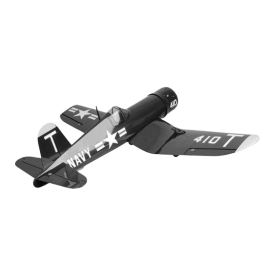
Sportsman Aviation has done it again, setting a new higher standard in ARF construction. This beautiful F4U Corsair ARF is
perfectly matched to the Magnum XLS .52 two-stroke engine or the Magnum XL .70RFS four-stroke engine. From the rotating
retracts to the beautiful covering job with world-wide recognized Oracover, this is a model you'll be proud to own and you can bet that
it will attract attention at the field. At the field and in the air, this F4U Corsair looks great and flies even better.
The F4U Corsair ARF is completely built-up from laser-cut plywood and balsa. The all-wood construction technique used on the
wing makes aligment and assembly a breeze. The design is durable and stout, ensuring your investment will give you long-lasting
enjoyment. In addition to the F4U Corsair's Oracover covering material, the airplane features preinstalled 90º rotating retracts,
molded wheel cups, adjustable engine mounting beams, dual aileron servos and rear-mounted elevator and rudder servos for crisp,
solid control response. Details, such as a molded fiberglass cowling, molded clear canopy, molded dummy radial engine and an
antenna mast, plus a high-quality hardware package, round out this specatacular model.
INSTRUCTIONS FOR FINAL ASSEMBLY
The Sportsman Aviation F4U Corsair ARF is distributed
exclusively by Global Hobby Distributors
18480 Bandilier Circle, Fountain Valley, CA 92708
All contents copyright © 2004, Global Hobby Distributors
Version V2.0 September 2004
IMPORTANT
The Sportsman Aviation F4U Corsair ARF is not intended for inexperienced pilots. It is in no way a trainer. If
you are not comfortable flying high-performance, sport aircraft, we strongly suggest returning the airplane (brand new, in the box
with all original packaging and your dated sales receipt) to the place of purchase.
F4U Corsair ARF Specifications:
Wing Span: 58.25 Inches (1480mm)
Wing Area: 618 Square Inches (39.88 dm
Length: 45.25 Inches (1150mm)
Weight RTF: 6.25 Pounds (2.8-2.9kg)
Wing Loading: 23.25 Ounces Per Square Foot (70 sq dm)
Functions: Ailerons, Elevator, Rudder, Throttle and Retracts
Engine Required: .46 - .52 Two-Stroke or .65 - .70 Four-Stroke
Radio Required: Four-Channel or More
Servos Required: Four Standard Ball Bearing Servos
One 180º Retract Servo
One Standard Servo
1
2
)
Kit Product Number 127534
Advertisement
Table of Contents

Related Manuals for Sportsman Aviation F4U Corsair ARF


Summary of Contents for Sportsman Aviation F4U Corsair ARF
- Page 1 Sportsman Aviation has done it again, setting a new higher standard in ARF construction. This beautiful F4U Corsair ARF is perfectly matched to the Magnum XLS .52 two-stroke engine or the Magnum XL .70RFS four-stroke engine. From the rotating retracts to the beautiful covering job with world-wide recognized Oracover, this is a model you'll be proud to own and you can bet that it will attract attention at the field.
-
Page 2: Table Of Contents
Section 4: Kit Contents ................ 6 Section 19: Balancing the F4U Corsair ARF ........45 Section 5: A Note About Covering ............7 Section 20: Lateral Balancing the F4U Corsair ARF ......45 Section 6: Wing Assembly ..............8 Section 21: Control Throws ..............46 Section 7: Belly Pan Installation ............ -
Page 3: Introduction
INTRODUCTION Thank you for purchasing the Sportsman Aviation F4U Corsair ARF. Before completing the final assembly of your new airplane, please carefully read through this instruction manual in its entirety. Doing so will ensure your success the first time around! -
Page 4: Section 1: Our Recommendations
This section describes our recommendations to help you in deciding which types of accessories to purchase for your new Sports- man Aviation F4U Corsair ARF. Please read through this entire section very carefully. We have provided you with tips and recommendations that, if followed, will result in a great flying airplane. -
Page 5: Section 2: Tools And Supplies Required
The part number for the Cirrus servo is compatible with all name-brand radio control systems. This servo uses a universal connector. SECTION 2: TOOLS AND SUPPLIES REQUIRED The tools and supplies listed below will be necessary to finish the assembly of your F4U Corsair ARF. We suggest having these items on hand before beginning assembly. -
Page 6: Section 4: Kit Contents
SECTION 4: KIT CONTENTS We have organized the parts as they come out of the box for easier identification during assembly. Before you begin assembly, group the parts as we list them below. This will ensure that you have all of the parts before you begin assembly and it will also help you become familiar with each part. -
Page 7: Section 5: A Note About Covering
SECTION 5: A NOTE ABOUT COVERING The covering material used on the Sportsman Aviation F4U Corsair ARF is real iron-on, heat-shrink covering material. It is possible with heat and humidity changes that the covering on your airplane may wrinkle or sag. This trait is inherent in all types of heat-shrink material. -
Page 8: Section 6: Wing Assembly
The F4U Corsair ARF uses C/A style hinges to hinge the control surfaces. These hinges are designed to be glued into place using thin C/A. Do not glue these hinges into place using any other type of glue, such as thick C/A or epoxy. Use of any adhesive other than thin C/A could result in failure of the hinges during flight. - Page 9 Push the aileron and its hinges into the hinge slots in the trailing edge of the wing panel. Remove the T-Pins and push the aileron into its final position. The aileron should be pushed firmly up against the trailing edge, so that there is a minimal hinge gap (no more than 1/32"...
- Page 10 Using a modeling knife, cut away all but one arm from a large "4-point" servo horn. Install the servo horn onto the servo, making sure that it's centered, as shown. Install the servo horn retaining screw to secure the servo horn to the servo. Temporarily place the aileron servo, along with two hardwood blocks, onto the bottom of the servo hatch cover.
- Page 11 STEP 3: INSTALLING THE SERVO HATCH COVERS Working with one servo hatch cover and wing panel for now, run the servo extension lead through the wing, using the factory-installed length of string; run it through the wing from the servo hatch and out the root rib.
- Page 12 Test-fit one wing joiner into one side of the center wing panel and the matching outer wing panel. It should slide easily into each wing panel up to the centerline you drew. IMPORTANT When the wing joiner is installed, it should not fit tightly into the wing panels.
-
Page 13: Section 7: Belly Pan Installation
IMPORTANT It is of the utmost importance to the integrity of the glue joint that you apply a generous amount of epoxy to both root ribs and the wing joiner. Not using enough epoxy can result in wing failure during flight. Slide the two wing panels together and realign them. - Page 14 While holding the wing-screw doubler in place, trace an outline around it, using a pencil. Using a modeling knife, cut away and remove the covering material from inside the outline you drew. IMPORTANT Never glue anything directly to covering material. Always remove the covering material first to ensure a strong glue joint.
-
Page 15: Section 8: Horizontal Stabilizer Installation
After you're satisfied with the fit of the belly pan, remove the wing, lay a long piece of waxed paper over the wing saddle, then reinstall the wing, making sure that the ends of the waxed paper are covering the joints between the fuselage and the leading and trailing edges of the wing. - Page 16 Slide the elevator joiner wire into the stabilizer mounting slot, as shown. IMPORTANT You MUST slide the elevator joiner wire into the stabilizer mounting slot BEFORE installing the stabilizer. If you don't, it will be impossible to slide the elevator joiner wire into place after the stabilizer is installed. Slide the horizontal stabilizer into the mounting slot and center it by carefully measuring out from each side of the fuselage to each end of the stabilizer (at the trailing edge only for now).
- Page 17 With the stabilizer held firmly in place, look from the front of the airplane at both the wing and the stabilizer. When aligned properly, the stabilizer should be parallel to the wing. If the stabilizer is out of alignment, remove it and use 220 grit sandpaper with a sanding block to sand down the higher side of the stabilizer mounting slot, then reinstall the stabilizer and check the alignment once more.
- Page 18 STEP 3: HINGING THE ELEVATOR HALVES Temporarily slide three elevator hinges into each elevator half. Don't glue them into place yet. Using a modeling knife, cut away and remove the covering material from over the precut slot in the leading edge of the root end of each elevator half.
-
Page 19: Section 9: Vertical Stabilizer Installation
While holding the elevator half tight against the stabilizer, pivot the elevator half down about 45º and apply 5-6 drops of thin C/A to the exposed area of each hinge. Turn the fuselage over and repeat for the other side of the hinges. Remove any C/A that may run down the hinge line, using C/A Debonder. - Page 20 Using a modeling knife, cut away and remove the covering material from over the tail wheel mounting bracket in the bottom of the fuselage. The mounting bracket is located 7-1/2" in front of the back edge of the fuselage. Slide the tail wheel wire through the mounting bracket, as shown. When positioned properly, the steering arm should rest on the mounting bracket and the prebent angle in the tail wheel wire should be toward the back of the fuselage.
- Page 21 Remove the vertical stabilizer and use a modeling knife to carefully cut away and remove the covering material from below the lines you drew. Remove the covering material from the base of the vertical stabilizer, too. WARNING When cutting through the covering to remove it, cut with only enough pressure to cut through only the covering itself.
- Page 22 Remove the rudder and carefully drill a 3/32" diameter, 1" deep pilot hole into the leading edge of the rudder, using the mark you drew as a guide. Be careful that you don't drill out through the sides of the rudder. IMPORTANT The pilot hole should be centered within the precut slot and drilled perpendicular to the leading edge.
-
Page 23: Section 10: Retractable Landing Gear Installation
SECTION 10: RETRACTABLE LANDING GEAR INSTALLATION YOU'LL NEED THE FOLLOWING PARTS FROM THE KIT: (1) Plywood Servo Tray (2) Main Gear Wheels (2) 9-5/8" Prebent Pushrod Wires (2) Plastic Wheel Cups (2) Pushrod Connectors w/Grub Screws, Washers & C-Clips (4) Wheel Collars w/Grub Screws (Large) (1) 1.5mm Hex Wrench (2) Notched Balsa Servo Tray Mounts YOU'LL NEED THE FOLLOWING TOOLS AND SUPPLIES:... - Page 24 Test-fit the retract servo tray assembly into the wing. When positioned properly, the notches in the two balsa mounts fit over the corresponding notches in the wing center-rib and the bottom of the two balsa mounts should fit firmly against the balsa sheeting on the bottom of the wing. IMPORTANT Depending on the height of your particular retract servo, you may need to trim the wing center-rib lower to allow the servo tray assembly to fit down firmly against the balsa sheeting.
- Page 25 Install the two adjustable pushrod connectors onto the servo wheel, using two flat washers (one on top of the servo wheel and one on the bottom) and the C-clip provided. Depending on the thickness of your servo wheel, you may need to use only one flat washer on the bottom.
- Page 26 With both retracts in the up and locked position, remove the servo wheel from the servo, slide the adjustable pushrod connectors over the ends of the pushrod wires, and then reattach the servo wheel to the servo. Use a rotary tool with a cutting disc to carefully cut away the excess pushrod wire, leaving about 5/16"...
-
Page 27: Section 11: Engine Installation
When satisfied with the fit, glue the wheel cup into the wing, using a thin layer of Formula 560 Canopy Glue. Remove any excess glue, using a paper towel and water, and hold the wheel cup securely in place, using pieces of masking tape, until the glue completely cures. - Page 28 Temporarily glue the two engine mounting beams to your engine's mounting lugs, using a couple of drops of thick C/A. IMPORTANT The taller portion of the mounting flanges on the engine mounting beams should be toward the top of your engine. The location of the engine is not important at this time.
-
Page 29: Section 12: Throttle Control System Installation
Install the engine using four M4 x 20mm socket-cap screws, eight M4 flat washers and four M4 lock nuts. Tighten the screws and lock nuts firmly to hold the engine securely into place. SECTION 12: THROTTLE CONTROL SYSTEM INSTALLATION YOU'LL NEED THE FOLLOWING PARTS FROM THE KIT: (1) 12"... - Page 30 STEP 2: INSTALLING THE THROTTLE PUSHROD WIRE Using a 5/32" diameter drill bit, drill a hole through the firewall for the throttle pushrod housing. The hole should be located so that it lines up as closely as possible with your engine's throttle arm, but far enough out from the center of the firewall so that the pushrod housing doesn't interfere with the fuel tank when it's installed later.
-
Page 31: Section 13: Fuel Tank Assembly And Installation
Enlarge the hole in the servo arm that is 9/16" out from the center of the servo arm, using a 5/64" diameter drill bit. Install the pushrod connector onto the servo arm, using two flat washers (one on top of the arm and one on the bottom) and the C-clip provided. - Page 32 Push the two aluminum tubes through the rubber stopper. Slide the large diameter metal plate over the tubes at the front of the stopper and slide the small diameter metal plate over the tubes at the rear of the stopper. Using a ruler, measure the distance that the two aluminum tubes protrude from the front of the stopper assembly.
-
Page 33: Section 14: Elevator Control System Installation
STEP 3: INSTALLING THE FUEL TANK Cut two pieces of silicone fuel tubing to a length of 8" and install them to the aluminum tubes at the front of the tank. PRO TIP Mark the ends of the silicone tubing "vent" and "pick-up" so you don't confuse them when it comes time to connect them to the engine later on. - Page 34 Install the rubber grommets and brass collets onto the elevator servo, making sure to install the collets with the flanges toward the bottom of the servo. Plug one 12" servo extension onto the elevator servo lead. To prevent the plugs from pulling apart during assembly, or worse, during flight, secure the plugs together, using a short piece of 3/8"...
- Page 35 Use a couple of pieces of masking tape, taped between the elevator and the stabilizer, to hold the elevator centered. Thread the nylon clevis onto the threaded pushrod wire. For security, thread the clevis on completely. Carefully snap the clevis into the third hole out from the base of the control horn.
-
Page 36: Section 15: Rudder Control System Installation
After you're satisfied with the alignment, cut two 3/8" long pieces from the 1/4" diameter tubing. Slide one piece of tubing over the clevis and one piece of tubing over the snap-keeper, then use a heat gun to carefully shrink the tubing. The tubing will prevent any chance of the clevis or snap-keeper from opening during flight. - Page 37 STEP 2: CONNECTING THE PUSHROD ASSEMBLY Thread the nylon clevis onto the threaded pushrod wire. For security, thread the clevis on completely. Carefully snap the clevis into one hole in the nylon steering arm. Use a couple of pieces of masking tape, taped between the rudder and the stabilizer, to hold the rudder centered. Using a modeling knife, cut away all but one arm from a "4-point"...
-
Page 38: Section 16: Aileron Control System Installation
Remove the masking tape from the rudder and double-check that the servo arm and the rudder are still centered. If the rudder is not centered, adjust the clevis until it is. Move the rudder right and left several times to ensure that the pushrod assembly does not bind. It should operate smoothly in both directions. -
Page 39: Section 17: Cowling Installation
Connect your radio system and plug one aileron servo into the receiver. Center the servo by double-checking that the aileron trim lever on your transmitter is centered. Enlarge the hole in the servo arm that is 13/16" out from the center of the servo arm, using a 5/64"... - Page 40 STEP 1: INSTALLING THE DUMMY RADIAL ENGINE Using a modeling knife, carefully cut out and remove the material from between each of the cylinders, then cut out and remove the material from the center of the dummy radial engine to allow clearance for your engine's drive washer.
- Page 41 Line up the cowling by centering the cutout in the dummy radial engine around your engine's drive washer, then by moving the cowling forward or backward until the front of the dummy radial engine is 1/16"-3/32" behind the front of the drive washer. Depending on the size and type of engine you've chosen, you may need to cut away a portion of the cowling to clear the engine's cylinder head.
-
Page 42: Section 18: Final Assembly
Slide the cowling partially into place and connect the fuel lines from the fuel tank to the fueling valve and carburetor. Slide the cowling into position and realign it. Install and tighten the four M2 x 8mm flange-head wood screws to hold the cowling firmly in place. - Page 43 STEP 2: INSTALLING THE CANOPY Using a pair of scissors, carefully cut out the canopy along the molded scribe line. Using 220 grit sandpaper with a sanding block, carefully sand the edges of the canopy smooth. Set the canopy onto the fuselage and align it. When aligned properly, the back edge of the canopy should be 3/4"...
- Page 44 If you will be flying your F4U Corsair ARF using a computer radio with mixing capabilities, you may want to plug each aileron servo lead into your receiver separately (into Ch. 1 and Ch. 6) to take advantage of your radio's mixing capabilities.
-
Page 45: Section 19: Balancing The F4U Corsair Arf
C/G be located any farther back than 3-1/2" (90mm). Balance the F4U Corsair ARF with the fuel tank empty and the retracts in the UP and LOCKED position. Install the wing onto the fuselage and verify that the retracts are up. Apply two short pieces of masking tape onto the top of the wing, 3-3/8"(85mm) back from the leading edge, measured at the fuselage sides. -
Page 46: Section 21: Control Throws
SECTION 21: CONTROL THROWS We recommend initially setting up the F4U Corsair ARF using the Test-Flying control throws. These control throws are suggested for initial test-flying because they will allow the airplane to fly smoother and make it easier to control. Once you're familiar with the flight characteristics of the airplane, you might want to increase the control throws to the Sport-Flying control throws. -
Page 47: Product Evaluation Sheet
Do not use staples and make sure our address faces out. Global Hobby Distributors will not disclose the information it collects to outside parties. Global Hobby Distributors does not sell, trade, or rent your personal information to others. - Page 48 _____________________________ _____________________________ Post Office will not deliver _____________________________ without proper postage (Return Address Here) Global Hobby Distributors Attn: Global Services 18480 Bandilier Circle Fountain Valley CA 92728-8610 Fold along dotted line...
Need help?
Do you have a question about the F4U Corsair ARF and is the answer not in the manual?
Questions and answers