Table of Contents
Advertisement
Quick Links
Advertisement
Table of Contents

Related Manuals for Motorola CPEI 775 Series


Summary of Contents for Motorola CPEI 775 Series
- Page 1 CPEi 775 Series User Manual User Manual...
-
Page 2: Table Of Contents
Contents Chapter 1: Desktop CPEi 775 User Guide Overview ..............1-1 Powerful Features in a Single Unit . - Page 3 Disposal of Motorola Equipment in EU Countries ....... . .
-
Page 4: Chapter 1: Desktop Cpei 775 User Guide
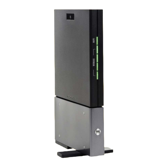
• Control - remote management capability allows easy detection and authentication once the unit is set up. • VoIP - two RJ11 ports allow for Voice over IP calls using your CPEi 775. • Wi-Fi - wireless LAN The features and the physical appearance of your Desktop CPEi device may differ slightly from the illustration. -
Page 5: Powerful Features In A Single Unit
Wi-Fi is enabled. Table 1-1 LED Indicator Interface Wi-Fi Signal Strength WAN WiMAX Desktop CPEi 775 User Guide Status Indicates if Wi-Fi is enabled or disabled. LED on, Wi-Fi is enabled. Full WiMAX Signal Strength is detected when all WiMAX Signal Strength LEDs are lit. -
Page 6: Back Of The Cpe
Desktop CPEi 775 User Guide Back of the CPE The back of the CPE unit contains the reset switch, AC Power Connector, Ethernet connector, Ethernet LED, Line 1 and Line 2 telephone ports. Figure 1-2: CPE Ports and Connections Table 1-2 Port Descriptions... - Page 7 Desktop CPEi 775 User Guide 68P09301A65-A FEB 2009...
-
Page 8: Chapter 2: Installation
Installation Chapter 2: Installation Overview To install the Desktop CPEi 775 Series, review the following sections: • Before You Begin • Easy Setup Before you Begin Before you begin installation, check that you have received the following items with your Desktop CPEi 775:... -
Page 9: Advanced Setup
Include the period (.) after http://mywimax. in order to access the login screen. NOTE 3. The Welcome to Motorola WiMAX CPE screen is displayed and prompts you for a password. Enter the IP address: http://192.168.15.1 into Address field in order to gain access to your CPE. -
Page 10: Setup Wizard And Authentication
• Re-type your new password in the Confirm New Login Password box. • Click Next. If you forget your password, you can reset it back to the default (motorola) password. To reset the password, press and hold the reset button on the back of your CPE for 5 or more seconds. - Page 11 • Check the box that is called “Auto Adjust for Daylight Savings Time” if you live in a region that observes Daylight Savings Time. This box is checked by default. • Click the Next button. Step 3 - WiMAX Security The WiMAX Security tab contains your authentication method.
-
Page 12: Restart Button
Installation Figure 2-2: Status Screen Restart Button Figure 2-3: Restart Button 68P09301A65-A FEB 2009... - Page 13 Installation 68P09301A65-A FEB 2009...
-
Page 14: Chapter 3: Basic Configuration
Basic Configuration Chapter 3: Basic Configuration Once the CPE setup has been completed, you can log in to your CPE from any computer on your home network. To log in type the device name in the address bar on your computer. The default device name is mywimax. This section describes the PERSONALIZE, INTERNET, STATUS, and Wi-Fi basic Menus that are available. -
Page 15: Password Tab
Password Tab The password tab allows you to enable/disable password protection. You can also change your password here. Be sure to click the Apply button when finished Table 3-1 Password Tab Field or Button Enable Login Password Protection New Login Password Confirm New Login Password Device Time Tab The Device Time tab allows you to establish the time zone for your location. -
Page 16: Restore Factory Settings Tab
Basic Configuration Restore Factory Settings Tab The Restore Factory Settings Tab resets your CPE to the manufacturers default settings. Be sure to click the Apply button if you are sure that you want to reset factory settings. Table 3-4 Restore Factory Settings Tab Field or Button Restore Factory Settings Internet Menu... -
Page 17: Wimax Security Tab
WiMAX Security Tab The WiMAX Security tab contains your authentication method. Check with your service provider to determine a user name and password are required for authentication purposes. Table 3-5 WiMAX Security Tab Field or Button Authentication Method User Name (EAP-TTLS/MS-CHAPv2 only) Enter the User Name supplied by your Password (EAP-TTLS/MS-CHAPv2 only) Realm If your authentication method is EAP-TLS, then a User Name and Password are not... -
Page 18: Dynamic Dns Tab
Basic Configuration Table 3-6 Firewall Tab Field or Button Enable ping from Internet Be sure to click the Apply button once you are finished. Dynamic DNS Tab Dynamic Domain Name Service (DDNS) allows a user with a non-static IP address to keep their domain name associated with an ever changing IP address. -
Page 19: Telephony Menu
Figure 3-3: Status Menu Network Tab The Network tab provides any status associated with your WiMAX Wireless Broadband connection. Telephony Tab The Telephony tab provides any status associated with your telephony connection. Telephony Menu The telephony menu allows you to manage your Voice over Internet Protocol (VoIP) services. - Page 20 Basic Configuration Figure 3-4: Telephony Menu Account Tab Please consult with your service provider for these settings. The Account Tab contains the following settings: Table 3-8 Account Tab Field or Button Line 1 User Name Line 1 Password Confirm Line 1 Password Line 2 User Name Line 2 Password Confirm Line 2 Password...
- Page 21 Ring Tone Tab The Ring Tone tab allows you to customize ring tones for your telephone(s). NOTE Table 3-9 Ring Tone Tab Field or Button Default Line 1 Ring Type Test Default Line 2 Ring Type Test Be sure to click the Apply button once you have made changes. Caller ID Tab The Caller ID tab allows you to manage the Caller ID functions for your telephones: Table 3-10 Caller ID Tab...
- Page 22 Basic Configuration Table 3-10 Caller ID Tab Field or Button Enable Line 2 Permanent Anonymous Outgoing Call Be sure to click the Apply button once you have made changes. Call Forwarding Tab The Call Forwarding tab allows you to manage the call forwarding features for your telephone(s).
- Page 23 Table 3-11 Call Forwarding Tab Field or Button Enable Line 2 Forwarding on No Answer Line 2 No Answer Forwarding to Number If “Line 2 No Answer Forwarding to Line 2 No Answer Forwarding Ring Count Enter the number of rings allowed before Enable Line 2 Forwarding on Busy Line 2 Busy Forwarding To Number Be sure to click the Apply button once you have made changes.
- Page 24 Basic Configuration Special Number Tab The Special Number tab provides a list of special dialing numbers for your VoIP Phone Service. The Special Number Tab contains the following: Table 3-13 Special Number Tab Field or Button Service Provider Contact Number Emergency Number Redial Blind Call Transfer...
- Page 25 Table 3-13 Special Number Tab Field or Button Automatic Callback Activate Automatic Callback Deactivate Do Not Disturb Activate Do Not Disturb Deactivate Calling Number Delivery Blocking Line Blocking Deactivate Call Waiting Toggle Anonymous Call Rejection Activate Anonymous Call Rejection Deactivate 3-12 Basic Configuration Description...
-
Page 26: Wi-Fi
Basic Configuration Wi-Fi The Wi-Fi basic menu helps manage the Wi-Fi related configurations. This menu includes Basic, and Security menus. For the Advanced settings, refer to the Advanced Configuration chapter “Wi-Fi Advanced” on page 7. Figure 3-5: Wi-Fi Basic Menu Wi-Fi Menu Wi-Fi Basic (Wireless LAN) network settings are configured at this menu which includes:... - Page 27 Table 3-14 Wi-Fi Basic Field or Button Operating Mode Operating Channels Wi-Fi Security The Wi-Fi Security menu enables you to choose the wireless LAN security protocol to enable authentication and secure data transmission on the Wi-Fi network. NOTE • Make sure the selected network security protocol is supported by the wireless devices on the network.
-
Page 28: Wep Configuration
Basic Configuration WEP Configuration Table 3-15 WEP Configuration Field or Button Authentication Type Encryption Strength Passphrase WPA/WPA2 Configuration Manage WPA/WPA2 security protocol settings. Underneath WPA/WPA2 Configuration. Table 3-16 WPA/WPA2 Menu Selections Field or Button Group Key Renewal Authentication Type 68P09301A65-A FEB 2009 Description A pull-down list with choices of:... - Page 29 Basic Configuration 3-16 68P09301A65-A FEB 2009...
-
Page 30: Chapter 4: Advanced Configuration
Advanced Configuration Chapter 4: Advanced Configuration The Advanced Configuration section describes the Port Forwarding, Local Address, and Control Panel menus. Port Forwarding Menu Port forwarding enables you to direct incoming traffic to specific LAN hosts (computers on your network) based on the protocol and port number. It is used to play Internet games or provide local services (such as web hosting) for a LAN group. -
Page 31: Forwarding Tab
Forwarding Tab Click the ADD button to create additional Port Forwarding rules. The Forwarding tab contains the following selections: Table 4-2 Forwarding Tab Field or Button Select Protocol WAN Port Start WAN Port End LAN IP Address LAN Port Start LAN Port End Enabled Be sure to click the Apply button once you have made changes. -
Page 32: Dhcp Server Tab
Advanced Configuration Figure 4-2: Local Address Menu DHCP Server Tab The DHCP Server tab enables Dynamic Host Configuration Protocol (DHCP) server functionality on the LAN, allowing the router to dynamically assign lease IP addresses to clients that connect to it from the local network. The DHCP Server Tab contains the following selections: Table 4-3 DHCP Server Tab Field or Button... -
Page 33: Lease Status Tab
Table 4-3 DHCP Server Tab Field or Button DHCP Ending IP Address DHCP Lease Time Be sure to click the Apply button once you have made changes. Lease Status Tab The Lease Status tab in the Local Address menu displays the active DHCP leases since the last reboot. -
Page 34: Control Panel
Advanced Configuration Table 4-5 Lease Reservation Tab Field or Button Select Client Host Name MAC Address IP Address Enabled Be sure to click the Apply button once you have made changes. Control Panel The Control Panel sections allows you to view/update your software information. The Control menu provides the following tabs: •... -
Page 35: Software Tab
Figure 4-3: Control Panel Menu Software Tab The Software tab manages the software on your CPE device. It is also where you can upgrade device software. Use the BROWSE button to browse your computer for additional software packages. Once you have located the software package/update you would like to add to your device, click the Upgrade button. -
Page 36: About Tab
Advanced Configuration Table 4-6 System Tab Field or Button Language Used in User Interface Enable WiMAX Radio Interface Enable LED Auto Refresh Interval Rebootstrap EMS About Tab The About Tab displays basic properties of your CPE device such as: Product Name, Model ID, Hardware Version, Serial Number, and the WiMAX MAC Address. - Page 37 Table 4-7 Wi-Fi Advanced Menu Field or Button Beacon Interval RTS Threshold Preamble Type Fragmentation Threshold DIMM Interval CTS Protection Mode Description Enter a value between 1 and 65,535 milliseconds. The Beacon Interval value indicates the frequency interval of the beacon.
- Page 38 Advanced Configuration Table 4-7 Wi-Fi Advanced Menu Field or Button Frame Burst Wireless Client Access List 68P09301A65-A FEB 2009 Description The default value is disabled. Frame burst allows packet bursting which will increase overall network speed though this is only recommended for approximately 1-3 wireless clients, Anymore clients and there can be a negative result and throughput will be affected.
- Page 39 Advanced Configuration 4-10 68P09301A65-A FEB 2009...
-
Page 40: Chapter 5: Configuring Tcp/Ip
Configuring TCP/IP Chapter 5: Configuring TCP/IP This section contains two examples of configuring TCP/IP in a Windows environment. Most computers already have the TCP/IP configuration enabled. Use the following procedures to verify that the configuration is set up. Configure all client computers on your network for TCP/IP (the protocol that controls communication among computers). - Page 41 Figure 5-2: Control Panel 3. Click Network and Internet Connections to display the Network and Internet Connections window: Figure 5-3: Network and Internet Connections 4. Click Network Connections. Skip to Step 6. 5. If a classic view like Figure 5-4 is displayed, double-click Network Connections to display the LAN or High-speed Internet connections.
- Page 42 Configuring TCP/IP Figure 5-4: Control Panel Classic View 6. Right-click the Local Area Connection. If more than one connection is displayed, be sure to select the one for your network interface. Figure 5-5: Network Connections 7. Select Properties from the pop-up menu to display the Local Area Connection Properties window: 68P09301A65-A FEB 2009...
- Page 43 Figure 5-6: Local Area Connection Properties 8. On the Local Area Connection Properties window, select Internet Protocol (TCP/ IP) if it is not selected. 9. Click Properties to display the Internet Protocol (TCP/IP) Properties window. Figure 5-7: Internet Protocol (TCP/IP) Properties 10.
-
Page 44: Configuring Tcp/Ip In Windows Vista
Configuring TCP/IP Configuring TCP/IP in Windows Vista 1. On the Windows desktop, click the Windows Logo on the left bottom corner to display the Start window. Then click Network. Figure 5-8: Network selection 2. When the Network windows appears, click the Network and Sharing Center from the action bar on the top of the window. - Page 45 Figure 5-9: Network and Sharing Center 3. After you click the Network and Sharing Center, the Network and Sharing Center window displays. Follow by clicking the Manage Network Connection from the task bar. Figure 5-10: 4. The network connections appear. Drag your mouse to the Local Area Connection and right click the mouse button.
- Page 46 Configuring TCP/IP Figure 5-11: Local Area Connection selection Figure 5-12: Properties selection 5. A series of protocols appear. Among them, check the Internet Protocol Version 4 (TCP/IPv4) and click Properties. 68P09301A65-A FEB 2009...
- Page 47 Configuring TCP/IP Figure 5-13: Internet Protocol Version 4 (TCP/IPv4) properties selection 6. At TCP/IPv4 Properties window, check Obtain an IP address automatically, and Obtain DNS server address automatically. Click OK to save the settings. 68P09301A65-A FEB 2009...
- Page 48 Configuring TCP/IP Figure 5-14: Internet Protocol Version 4 (TCP/IPv4) Properties window 7. When you have completed the setting updates, click OK to exit. 68P09301A65-A FEB 2009...
- Page 49 Configuring TCP/IP 5-10 68P09301A65-A FEB 2009...
-
Page 50: Chapter 6: Troubleshooting
Troubleshooting Chapter 6: Troubleshooting Power • Check that the AC power adapter is properly plugged into the electrical outlet and into the Desktop CPE. • Check that the electrical outlet is working. A Computer Cannot Log On to the CPE Check that the Ethernet cable is properly connected to the Desktop CPE unit and the computer. - Page 51 Troubleshooting 68P09301A65-A FEB 2009...
-
Page 52: Chapter 7: Important Safety And Legal Information
Important Safety and Legal Information Chapter 7: Important Safety and Legal Information Your Motorola WiMAX Wireless Broadband Gateway is designed and tested to comply with a number of national and international standards and guidelines (listed below) regarding human exposure to RF electromagnetic energy. -
Page 53: Industry Canada Statement
• Connect the equipment into an outlet on a circuit different from that to which the receiver is connected. • Consult the dealer or an experienced radio/TV technician for help. This Gateway desktop transmitter must not be co-located or operating in conjunction with any other antenna or transmitter. -
Page 54: Eu Declaration Of Conformity
EN 60950-1:2006 (IEC 60950-1:2005) Caring for the Environment The following information is provided to enable regulatory compliance with the European Union (EU) Directive 2002/96/EC Waste Electrical and Electronic Equipment (WEEE) when using Motorola Networks equipment in EU countries. 68P09301A65-A FEB 2009... -
Page 55: Disposal Of Motorola Equipment In Eu Countries
Hazardous Substances (EU RoHS) directive. Please do not dispose of Motorola Networks equipment in landfill sites. In the EU, Motorola Networks in conjunction with a recycling partner will ensure that equipment is collected and recycled according to the requirements of EU environmental law. -
Page 56: Copyrights And Trademarks
Motorola, Inc. does not assume any liability arising out of the application or use of any product, software, or circuit described herein;... - Page 57 High Risk Activities. Trademarks MOTOROLA and the Stylized M Logo are registered in the US Patent & Trademark Office. All other product or service names are the property of their respective owners. © Motorola, Inc., 2008...
- Page 58 MOTOROLA and the Stylized M Logo are registered in the US Patent & Trademark Office. All other product or service names are the property of their respective owners. © 2009 Motorola, Inc.