Advertisement
Quick Links
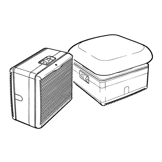
W indow & Roof Models
Installation, Set-up and Operating Instructions
READ INSTRUCTIONS IN CONJUNCTION W ITH ILLUSTRATIONS
READ AND SAVE THESE INSTRUCTIONS
(Community Design Nos. 000112507-0001-0004 & 000112065-0001)
T-SERIES
Stock Ref. Nos.
W IRED
456165A (9" W W )
456168A (9" RF)
456173A (12" W W )
456176A (12" RF)
230V/1/50Hz
W IRELESS
456169A (9" W W )
456172A (9" RF)
456177A (12" W W )
456180A (12" RF)
Advertisement

Subscribe to Our Youtube Channel
Related Manuals for Vent-Axia LoWatt T-SERIES


Summary of Contents for Vent-Axia LoWatt T-SERIES
- Page 1 T-SERIES W indow & Roof Models Installation, Set-up and Operating Instructions Stock Ref. Nos. W IRED W IRELESS 456165A (9" W W ) 456169A (9" W W ) 456168A (9" RF) 456172A (9" RF) 456173A (12" W W ) 456177A (12" W W ) 456176A (12"...
- Page 2 READ INSTRUCTIONS IN CONJUNCTION WITH THE ILLUSTRATIONS IMPORTANT THE FAN MUST BE SITED AND CONNECTED IN ACCORDANCE WITH CURRENT IEE REGULATIONS (UK) OR THE APPROPRIATE STANDARDS IN YOUR COUNTRY. THIS APPLIANCE IS NOT SUITABLE FOR INSTALLATION IN A SHOWER CUBICLE OR ENCLOSURE AND MUST BE SITED AWAY FROM ANY SOURCE OF WATER SPRAY, AND MUST BE OUT OF REACH OF A PERSON USING A FIXED BATH OR SHOWER.
-
Page 3: Fan Dimensions
When fixing thickness exceeds 32mm, the unit should be secured with Extended Fixing Rods. If the unit is to be installed in a location exposed to severe wind turbulence or in non-vertical panes, thicker glass will be required – consult your nearest Vent-Axia Sales, Service and Distribution Centre. SIZE... -
Page 5: Installation
Refit the housing ensuring that no internal wires are trapped between the housing and base. Engage the two side catches. Tighten the two side catch screws. F10 Replace the indoor grille with the louvres slanting upwards, with the Vent-Axia logo at the bottom of the grille, and secure with the retaining screw. - Page 6 F3i/ ii FOR SPEED CONTROL REFER TO THE RELEVANT FITTING AND WIRING INSTRUCTIONS SUPPLIED WITH THE WIRED/ WIRELESS CONTROL.
- Page 7 TYPICAL ROOF INSTALLATIONS USING VENT-AXIA ACCESSORIES (A) ROOF LIGHT All T-Series roof models are designed to fit directly into horizontal and sloping glass including wired cast and sealed double glazing up to 32mm thick. For materials of greater thicknesses extended fixing rod sets are available, allowing the unit to be fixed through a spacing of up to 370mm.
- Page 8 WIRING THE CONNECTOR SOCKET • Ensure that the supply (Voltage, Frequency and Phase) complies with the rating label. • This appliance must be earthed. F11 Remove the top cover from the connector socket by undoing the 2 retaining screws. F12 Lift up lever and slide out top cover. F13 Loosen cable clamp screws and pass the cable through the clamp.
- Page 9 Fig. 3 (Wired version only) Please refer also to the speed controller fitting and wiring instructions. ISOLATE FROM THE POWER SUPPLY PRIOR TO ANY MAINTENANCE AND CLEANING USER INSTRUCTIONS • At intervals appropriate to the installation, inspect and clean the fan to ensure there is no build up of grease or dirt on the impeller or the motor.
- Page 10 G16 Refit the housing ensuring that no internal wires are trapped between the housing and base. G17 Engage the two side catches. Tighten the two side catch screws. G18 Replace the indoor grille with the louvres slanting upwards and the Vent-Axia logo at the bottom of the grille, then secure with the retaining screw.
- Page 11 G14a G14b...
- Page 12 ‘Guarantee Claim’ stating the nature of the fault and providing proof of the date and source of purchase. As part of the policy of continuous product improvement Vent-Axia reserve the right to alter specifications without notice Head Office: Fleming Way, Crawley, West Sussex RH10 9YX...
Need help?
Do you have a question about the LoWatt T-SERIES and is the answer not in the manual?
Questions and answers