Table of Contents
Advertisement
Quick Links
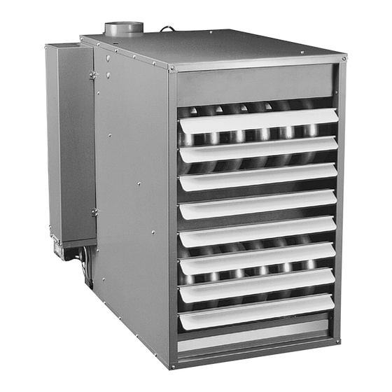
TUBULAR GAS FIRED PROPELLER UNIT HEATERS
ATTENTION: READ THIS MANUAL AND ALL LABELS ATTACHED TO THE UNIT CAREFULLY BEFORE
ATTEMPTING TO INSTALL, OPERATE OR SERVICE THESE UNITS! CHECK UNIT DATA PLATE FOR TYPE OF GAS
AND ELECTRICAL SPECIFICATIONS AND MAKE CERTAIN THAT THESE AGREE WITH THOSE AT THE POINT OF
INSTALLATION. RECORD THE UNIT MODEL AND SERIAL No.(s) IN THE SPACE PROVIDED. RETAIN FOR FUTURE
REFERENCE.
Model No.
The use and storage of gasoline or other flammable vapors and liquids in open containers in
the vicinity of this appliance is hazardous.
cause property damage, injury, or death. Read the installation, operating, and
maintenance instruction thoroughly before installing or servicing this equipment.
instructions to avoid exposure to fuel substances, or substances from incomplete
combustion, which can cause death or serious illness. The state of California has
determined that these substances may cause cancer, birth defects, or other
reproductive harm.
Installer Please Note: This equipment has been test fired and inspected. It has been
shipped free from defects from our factory. However, shipment and installation
problems such as loose wires, leaks, or loose fasteners may occur. It is the installer's
responsibility to inspect and correct any problem that may be found.
RECEIVING INSTRUCTIONS
Inspect shipment immediately when
received to determine if any damage
has occurred to the unit during
shipment. After the unit has been
uncrated, check for any visible
damage to the unit. If any damage is
found, the consignee should sign
the bill of lading indicating such
damage and immediately file claim
for damage with the transportation
company.
07/03
INSTALLATION INSTRUCTIONS AND PARTS LIST
If you smell gas:
1. Open windows.
2. Don't touch electrical switches.
3. Extinguish any open flame.
4. Immediately contact your gas supplier.
Improper installation, adjustment, alteration, service, or maintenance can
APPROVED FOR USE IN CALIFORNIA
Install, operate, and maintain unit in accordance with the manufacturer's
INSTALLER'S RESPONSIBILITY
Serial No.
FOR YOUR SAFETY
FOR YOUR SAFETY
260 NORTH ELM ST., WESTFIELD, MA 01085
TEL: (413) 564-5540
www.sterlinghvac.com
Please utilize this toll free number to contact your local
representative 800-490-2290.
HVAC PRODUCTS
FAX: (413) 562-5311
MODELS: TF-100, 125, 150, 175,
200, 250, 300, 350, 400
(S) TBIM-5R
J30-05375B
Advertisement
Table of Contents

Related Manuals for Sterling TUBULAR GAS FIRED PROPELLER UNIT HEATERS


Summary of Contents for Sterling TUBULAR GAS FIRED PROPELLER UNIT HEATERS
- Page 1 J30-05375B INSTALLATION INSTRUCTIONS AND PARTS LIST TUBULAR GAS FIRED PROPELLER UNIT HEATERS ATTENTION: READ THIS MANUAL AND ALL LABELS ATTACHED TO THE UNIT CAREFULLY BEFORE ATTEMPTING TO INSTALL, OPERATE OR SERVICE THESE UNITS! CHECK UNIT DATA PLATE FOR TYPE OF GAS AND ELECTRICAL SPECIFICATIONS AND MAKE CERTAIN THAT THESE AGREE WITH THOSE AT THE POINT OF INSTALLATION.
-
Page 2: Table Of Contents
TABLE OF CONTENTS SPECIFICATIONS VENTING ........... 14, 15, 16, 17, 18 Basic Description ............ 2 OPERATION Performance & Specification Data ......4 Explanation of Controls and Operation ....19 GENERAL SAFETY INFORMATION Main Burner Orifice Schedule ....... 20 Installation Codes ..........2, 3 Adjustments ............ -
Page 3: General Safety Information
GENERAL SAFETY INFORMATION Failure to comply with the general Do not attempt to convert the safety information may result in extensive heater for use with a fuel other than the one property damage, severe personal injury, or intended. Such conversion is dangerous, as it will create the risks previously listed. -
Page 4: Installation
Table 1 - Performance and Dimensional Data - Tubular Propeller Unit Heater Unit Size PERFORMANCE DATA† Input - BTU/Hr. 100,000 125,000 150,000 175,000 200,000 250,000 300,000 350,000 400,000 (kW) (29.3) (36.6) (43.9) (51.2) (58.6) (73.2) (87.8) (102.5) (117.1) Output - BTU/Hr. 81,000 101,250 121,500... -
Page 5: Installation
INSTALLATION AIR DISTRIBUTION: Direct air towards areas of Do not install unit heaters in maximum heat loss. When multiple heaters are involved, corrosive or flammable atmospheres! Premature failure of, or severe damage to the unit will circulation of air around the perimeter is recommended where heated air flows along exposed walls. -
Page 6: Installation Codes
INSTALLATION (continued) CLEARANCES: Each Gas Unit Heater shall be located Figure 3A with respect to building construction and other equipment so as to permit access to the Unit Heater. Clearance between vertical walls and the vertical sides of the Unit Heater shall be no less than 6 inches (152mm). -
Page 7: Gas Piping
GAS PIPING To avoid damage or possible personal injury, do not connect gas piping to this unit until a supply line pressure/leak test has been completed. Connecting the unit before completing the pressure/leak test may damage the unit gas valve and result in a fire hazard. Do not rely on a shut-off valve to isolate the unit while conducting gas pressure/leak tests. - Page 8 PIPE INSTALLATION 1. Install the gas piping in accordance with applicable Figure 4 - Pipe Installation, Standard Controls local codes. 2. Check gas supply pressure. Each unit heater must be connected to a manifold pressure and a gas supply capable of supplying its full rated capacity as specified in Table 4.
-
Page 9: Electrical Connections
ELECTRICAL CONNECTIONS Figure 5a - Low-voltage T Thermostat Wiring HAZARDOUS VOLTAGE! Single Stage DISCONNECT ALL ELECTRIC POWER INCLUDING REMOTE DISCONNECTS BEFORE Figure 5b - SERVICING. Failure to Low-voltage disconnect power before Thermostat Wiring servicing can cause severe Two Stage personal injury or death. Standard units are shipped for use on 115 volt, 60 hertz, single phase electric power. - Page 10 ELECTRICAL CONNECTIONS (continued) Figure 5d & 5e - Tubular Units Equipped with Hot Surface Pilot (Single Stage): 100/400 Unit Sizes with Natural Gas and Propane (LP) Gas Figure 5d Figure 5e (Primary) (Alternate) [HWSV9540/SV9640 [HWSV9500/SV9600/SV9501/SV9601 Hot Surface Ignition Gas Controls] Hot Surface Ignition Gas Controls]...
- Page 11 ELECTRICAL CONNECTIONS (continued) Figure 5f - Tubular Units Equipped with S8600 (Single Stage) Ignition: Optional for Tubular 100/400 Unit Sizes with Natural Gas and Propane (LP) Gas...
- Page 12 ELECTRICAL CONNECTIONS (continued) Figure 5g - Tubular 100/400 Unit Sizes with Optional 2 Stage Ignition...
-
Page 13: Venting
VENTING ANSI now organizes vented Category I Category IV appliances into four categories. Includes non-condensing Covers condensing appliances with appliances with negative vent positive vent pressure. Venting Categories pressure, like the traditional NOTICE: Category II and IV do atmospheric unit heater. not apply to equipment specified Condensing Condensing... - Page 14 HORIZONTALLY VENTED UNIT HEATERS (CATEGORY III) Horizontal venting arrangements are designed to be The vent terminal must be at least 12 inches (305mm) used with single wall vent pipe. Horizontal venting from the exterior of the wall that it passes through to arrangements must terminate external to the building prevent degradation of the building material by flue using either single wall or double wall (Type B) vent.
- Page 15 VENTING (continued) Figure 6 - Vertically Vented Tubular Unit Heater – Category I Figure 7 - Horizontally Vented Tubular Unit Heater – Category III ADDITIONAL REQUIREMENT FOR CANADIAN INSTALLATIONS REFER TO SPECIFICATION TABLE AND INSTALLATION MANUAL FOR PROPER USAGE. * The following instructions apply to Canadian installations in addition to installation and operating instructions. 1.
- Page 16 VENTING (continued) Figure 8A Figure 8B...
- Page 17 VENTING (continued) Figure 9A Figure 9B...
-
Page 18: Operation
OPERATION POWER VENTED PROPELLER UNITS INTERMITTENT PILOT IGNITION EXPLANATION OF CONTROLS (See Figure 10): START-UP (Also refer to lighting instruction plate 1. The unit heater is equipped with a power venter equipped on the unit) system consisting of a power venter motor and 1. -
Page 19: Main Burner Orifice Schedule
PRIMARY AIR SHUTTER ADJUSTMENT Primary air adjustment is made at the factory. No field adjustments are necessary. GAS INPUT RATE Check the gas input rate as follows (Refer to General 2. PROPANE GAS: An exact manifold pressure of Safety Information section for metric conversions). 10.0 inches W.C. -
Page 20: Adjustments
Table 5A TUBULAR UNIT HEATER HIGH ALTITUDE DERATION NATURAL GAS PROPANE (LP) GAS This Tubular Unit Heater has been manufactured utilizing standard burner orifices and a normal manifold pressure Heating* Manifold Heating* Manifold setting as per the specifications shown on your unit Altitude Value Pressure... - Page 21 Table 6 - Tubular Propeller Trouble Shooting Guide POSSIBLE CAUSE(S) CORRECTIVE ACTION SYMPTOMS A. Flame lifting from burner ports. 1. Pressure regulator set too high. 1. Reset manifold pressure. Refer to “Operation”. 2. Defective Regulator. 2. Replace regulator section of combination gas valve or complete valve.
- Page 22 Table 6 - Tubular Propeller Trouble Shooting Guide (continued) POSSIBLE CAUSE(S) CORRECTIVE ACTION SYMPTOMS 1. Tighten all electrical connections. L. Rapid burner cycling. 1. Loose wire connections at gas valve or thermostat. 2. Excessive thermostat heat anticipation. 2. Adjust thermostat heat anticipator for longer cycles.
- Page 23 Table 6 - Tubular Propeller Trouble Shooting Guide POSSIBLE CAUSE(S) CORRECTIVE ACTION SYMPTOMS 1. Fan relay heater element improperly 1. Be sure fan relay heater terminal are T. Cold air is delivered on start up. wired. connected per diagrams. U. Cold air is delivered during heater 1.
-
Page 24: Warranty
Table 6 - Tubular Propeller Trouble Shooting with LED Indicator Assistance No Cycling or appliance power INDICATES CHECK/REPAIR LED STATUS or thermostat call for heat No power to system control 1. Line voltage input power at L1 since appliance failure has and L2 connector. -
Page 25: Maintenance
MAINTENANCE 5. Remove any dirt, dust, or other foreign matter from PERIODIC SERVICE the burners using a wire brush and/or compressed NOTICE: The heater and vent system should be air. Ensure that all parts are unobstructed. Inspect and clean the pilot burner if necessary. checked once a year by a qualified technician. - Page 26 IDENTIFICATION OF PARTS PROPELLER UNIT HEATERS Figure 11 - Propeller Parts Figure 12 - Component Parts Fan Blade Fan Guard Hardware Hardware D4430 Figure 13 - Heat Exchanger Assembly Figure 14 - Electrical Control Panel...
-
Page 27: Replacement Parts
Figure 15 - Power Venter Assembly Figure 16 - Power Venter Assembly (100/250 Unit Sizes Shown) (300/400 Unit Sizes Shown) Figure 17 - Turbulator/High Limit Location HOW TO ORDER REPLACEMENT PARTS Please send the following information to your local representative: if further assistance is needed, contact the manufacturer's customer service department. - Page 28 GAS EQUIPMENT START-UP Customer ____________________________________ Job Name & Number _________________________ PRE-INSPECTION INFORMATION With power and gas off. Type of Equip: Unit Heater Serial Number _________________________ Model Number __________________________ Name Plate Voltage: _____________ Name Plate Amperage: _____________ Type of Gas: Natural Tank Capacity _______ lbs.
Need help?
Do you have a question about the TUBULAR GAS FIRED PROPELLER UNIT HEATERS and is the answer not in the manual?
Questions and answers