Table of Contents
Advertisement
Advertisement
Table of Contents

Related Manuals for Parklands PZT-42

Summary of Contents for Parklands PZT-42
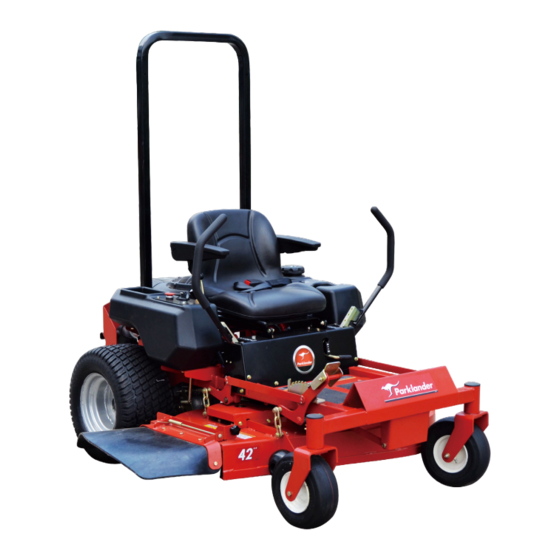
- Page 1 Zero Turn Mower PZT-42...
- Page 2 General General Information Information General General Information Information Thank you for choosing Parklander as your preferred lawn mowing machine. This owner’s manual contains information on safety instructions, assembly requirements,operation instructions and maintenance requirements to assist you in the correct use of the machine. The manual also contains information on adjustment settings and troubleshooting procedures should you require them.
-
Page 3: Table Of Contents
CONTENTS CONTENTS CONTENTS CONTENTS SPECIFICATIONS............................- 1 - 1. SAFETY SYMBOLS..........................- 2 - 2. SAFETY DECALS...........................- 2 - 3. SAFETY INFORMATION........................- 5 - 3.1. Trainings............................- 5 - 3.2. Preparation............................- 5 - 3.3. Fuel Handling Safety........................- 5 - 3.4. Operational Safety........................... - 6 - 3.5. - Page 4 6.11. Balancing the Mower Blades.......................- 20 - 6.12. Blade Installation.........................- 20 - 7. ADJUSTMENTS............................- 21 - 7.1. Cutting Height Adjustment......................- 21 - 7.2. Deck Leveling Adjustment......................- 21 - 7.3. Deck Belt Adjustment........................- 22 - 7.4. Dump Drive Belt Adjustment......................- 22 - 7.5.
-
Page 5: Specifications
SPECIFICATIONS SPECIFICATIONS SPECIFICATIONS SPECIFICATIONS Engine Engine B&S two cylinder, 4 cycle Engine Engine Model No. Professional Professional Series Series M40G7 M40G7 Professional Professional Series Series M40G7 M40G7 Horsepower (G.I.H.P.) 20HP(14.91kw) Displacement 656cc. No-load r.p.m. 3600r/min Charging System 12VDC 12.5 amp. negative ground Starter Electric Electrical System... -
Page 6: Safety Symbols
1. SAFETY SAFETY SYMBOLS SAFETY SAFETY SYMBOLS SYMBOLS SYMBOLS This This SAFETY SAFETY ALERT ALERT SYMBOL SYMBOL SYMBOL is used This This SAFETY SAFETY ALERT ALERT SYMBOL both in this manual and on the machine to alert you to important safety messages which must be followed to avoid accidents. - Page 7 Familiarize yourself with the following � safety decals and instruction labels. They are critical for the safe operation of your machine. 1.On The Front Frame 6.Behind Of The Rear Wheel,LH&RH 2.Besides The Belt Shields,LH&RH 7.On The Fuel Tank 3.Besides The Belt Shields,LH&RH 8.
- Page 8 10.On The Mower Deck 16.On The Left of the Engineer 11.On The Mower Deck 12.On The Right of the Engineer 13.On The Front Left Of The Frame 14.On The Carrier Ratchet On The Front Fender On The Roll Bar 19.Besides Mounting Plate Of Fuse 15.On The Front Of Deck - 4 -...
-
Page 9: Safety Information
20.On The Front Fender While mowing,always wear tight and � belted clothing. Wear protected footwear. Never operate the machine in bare feet, open toed footwear . Walk around machine and visually � inspect for damaged, loose, or missing components. DO DO NOT NOT operate unless all components... -
Page 10: Operational Safety
Never smoke when handling gasoline, Start engine from operator’s seat after � � and keep away from open flames or where disengaging PTO and placing steering gasoline fumes may be ignited by a spark. levers into the swing-out (neutral lock) Store gasoline in an approved container position. -
Page 11: Maintenance Safety
crossing roadways. and batteries can harm the environment This machine is not equipped for and people. Dispose of waste products � highway use, especially when safety properly. lighting and marking is required. It is Never attempt to disconnect or alter any �... -
Page 12: Assembly Instructions
Sand areas where paint is chipped and 4.4. 4.4. 4.4. 4.4. Install Install Install Install Steering Steering Steering Steering Lever Lever Lever Lever � repair to prevent rust. Lubricate all 4.3.1 4.3.1 4.3.1 4.3.1 Loosen and remove the two bolts locations to prevent moisture damage and springs which attach to the control during storage. -
Page 13: Service Battery
4.6. 4.6. 4.6. 4.6. Service Service Service Service Battery Battery Battery Battery digital voltmeter, Locate the voltage of the battery in the table below and charge the DANGER DANGER DANGER DANGER battery for the recommended time (Refer to Table 1) interval to bring the charge up to a Charging the battery may produce explosive full charge of 12.6Volts or greater. - Page 14 controls and comfortable with your ability. on the console.Choke control is used to aid in starting a cold engine.Put the Choke We recommend you practice in a flat open control up or down can control the area at half throttle until you are comfortable opening degree of the engine choke,the with all the controls.
- Page 15 leftward until the lever catches in are safely and securely attached. corresponding the notch of the fender and Make sure the discharge shield or � locks to set the brakes “on”. Push the restriction plate is installed brake lever down to release the brakes discharge opening on the mower deck.
- Page 16 secure; the cutting edge should be Test safety interlock systems (Refer to � positioned in the direction of blade Table 2). Perform these tests in a clear rotation (clockwise as viewed from top of open area and keep bystanders away. If mower deck).
- Page 17 Help Help Help Help prevent prevent prevent prevent personal personal personal personal injury. injury. injury. injury. Learn Learn Learn Learn use use of of of of operate operate machine machine around around DO NOT NOT operate operate the the machine machine around around the steering...
- Page 18 Figure 9 - 14 -...
-
Page 19: Mowing
Pushing both levers forward at the same objects. objects. objects. objects. Never Never Never Never assume assume assume assume an an an an area area area area is is is is clear, clear, clear, clear, � time will move the machine forward. always always always... -
Page 20: Uneven Terrain
weather and encourage weed growth during though brakes functioning properly. the growing season. Avoid sudden starts and acceleration Mow with uncut grass to the left. This will � when traveling forward uphill as mower distribute the clippings over the cut area. may tip backwards. -
Page 21: Transporting Machine
5.9.2 5.9.2 5.9.2 5.9.2 Move ignition switch to “OFF” a ramp. position (upright) and remove key. Back machine up ramp and drive forward � down ramp. CAUTION CAUTION CAUTION CAUTION Use only a single, full width ramp; DO � � � � NOT use use individual individual... -
Page 22: Maintenance
6.2. 6.2. 6.2. 6.2. Lubrication Lubrication Lubrication Lubrication 6. MAINTENANCE MAINTENANCE MAINTENANCE MAINTENANCE DO NOT let excess grease collect on or around parts, particularly when operating CAUTION CAUTION CAUTION CAUTION sandy areas. accompanying Always Always perform perform maintenance maintenance with with Always Always perform... -
Page 23: Battery Maintenance
(Refer to decal on wheel for correct tire air and acid acid acid acid out out of of of of the the reach reach reach reach of of of of children. children. children. children. pressure) 6.7. Deck Cleaning 6.7. 6.7. 6.7. -
Page 24: Blade Removal
that they are mounted securely and are in 13) when grinding. DO NOT change the DO NOT good condition. Replace any blade that is mower blade bevel. bent, excessively nicked, worn, or has any 6.12.4 6.12.4 6.12.4 The mower blade should have a 6.12.4 other damage. -
Page 25: Adjustments
replacement replacement replacement replacement blades. blades. blades. blades. They They They They are are made made made made of of of of When deck reaches desired height, push on special special special special steel steel steel steel alloys alloys alloys alloys and and subjected subjected... - Page 26 initial use. Periodically belt should be checked for proper tension, following the procedure below(Refer to Figure 19). 7.3.1 7.3.1 7.3.1 7.3.1 Position the mower deck in the MEASURE MEASURE lowest (1inch) cut height setting and Level Surface remove the left belt shield. Figure 17 7.3.2 7.3.2...
-
Page 27: Neutral Adjustment
The way is similar to the above of Deck securely. Belt Adjustment ,The idler spring (B) body 7.5.5 7.5.5 7.5.5 7.5.5 If the left wheel needs to be length should measure approximately 10cm adjusted,use the same way to adjust the left inches for proper belt tension(Refer to wheel. -
Page 28: Troubleshooting
7.7.4 7.7.4 7.7.4 7.7.4 If the spring is not within this range, when when when when the the engine engine engine engine is is is is stopped stopped stopped stopped and and the release the parking brake and turn the parking parking parking... - Page 29 Problem Possible Cause Corrective Action Problem Problem Problem Possible Possible Possible Cause Cause Cause Corrective Corrective Corrective Action Action Action 1.Fuel tank is empty. 1.Fill the fuel tank. 2.Oil level in the crankcase 2.Add oil to the crankcase. is low. 3.The throttle and choke 3.Be sure the throttle control is midway are not in the correct...
- Page 30 Problem Possible Cause Corrective Action Problem Problem Problem Possible Possible Possible Cause Cause Cause Corrective Corrective Corrective Action Action Action 1.Blade(s) not sharp. 1.Sharpen the blade(s). 2.Cutting blade(s) is/are 2.Install new cutting blade(s). bent. 3.Level mower deck from side-to-side 3.Mower deck is not level. and front-to-rear.
- Page 31 Problem Possible Cause Corrective Action Problem Problem Problem Possible Possible Possible Cause Cause Cause Corrective Corrective Corrective Action Action Action 1.Fuse is blown. 1.Replace fuse. Check coil 2.Low voltage supply at resistance,battery charge, charging the clutch. system, and wiring connections and 3.Damaged coil.
-
Page 32: Electrical Diagram
9. ELECTRICAL ELECTRICAL DIAGRAM ELECTRICAL ELECTRICAL DIAGRAM DIAGRAM DIAGRAM - 28 -... - Page 33 - 29 -...
Need help?
Do you have a question about the PZT-42 and is the answer not in the manual?
Questions and answers