Table of Contents
Advertisement
Advertisement
Chapters
Table of Contents

Related Manuals for Star Micronics NX-1000 series


Summary of Contents for Star Micronics NX-1000 series
- Page 1 DOT MATRIX PRINTER NX-1000SERIES LC-10SERIES TECHNICAL MANUAL [ NINTH EDITION ]...
- Page 2 However, should any errors be detected, STAR would greatly appreciate being informed of them. • The above notwithstanding, STAR can assume no respon- sibility for any errors in this manual. © Copyright 1987 Star Micronics Co.,Ltd.
-
Page 3: General Specifications
INTRODUCTION This manual describes dot matrix printers as shown below. It is intended for use as a reference for periodic inspections and maintenance procedures. This manual is prepared for use at a technical level and not for the general user. Model Interface Mono/Colour... -
Page 4: Table Of Contents
CHAPTER 1 GENERAL SPECIFICATIONS General Specifications ..................1-1. Parallel Type ......................3 1-2. Commodore Type....................4 External Appearance and Composition .............. 2-1. Names of Parts ......................7 2-2. DIP switch settings ....................9 Connector Signals ....................3-1. Parallel Interface ....................11 3-2. - Page 5 GENERAL SPECIFICATIONS – 2 –...
-
Page 6: General Specifications
GENERAL SPECIFICATIONS General Specifications 1-1. Parallel Type Printing Printing method Serial impact dot matrix Printing speed 120 characters per second (in Draft pica for Ver. 1 and Ver. 1.5) 30 characters per second (in NLQ pica for Ver. 1 and Ver. 1.5) 150 characters per second (in Draft pice for Ver. -
Page 7: Commodore Type
GENERAL SPECIFICATIONS Printer Dimensions Height 108 mm (4.3 inches) Width 384 mm (15.1 inches) Depth 287.5 mm (11.3 inches) Weight 4.7 kg (10.3 pounds) Power 120 VAC±10%, 60Hz. 220 VAC±10%, 50/60Hz. 240 VAC±10%, 50/60Hz. Power consumption Typ. 30W, Max. 60W Environment Operating temperature: 5 to 40°C (41 to 104°F) Operating humidity: 10 to 80%, non condensation... - Page 8 GENERAL SPECIFICATIONS Printing Dot matrix size 9 × 9 dots (Draft pica) Character matrix 18 × 23 dots (Courier and Orator pica) 18 × 18 dots (Sanserif pica,elite) 7 × 11 dots (Block graphics,pica) 18 × 19 dots (Courier and Orator elite) 18 ×...
- Page 9 GENERAL SPECIFICATIONS Fig. 1-1 External Dimensions – 6 –...
-
Page 10: External Appearance And Composition
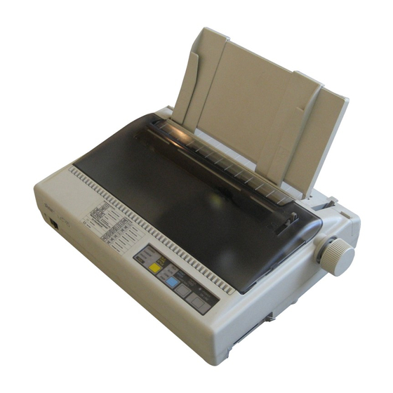
GENERAL SPECIFICATIONS External Appearance and Composition 2-1. Names of Parts Fig. 1-2 Front and rear views of the printer – 7 –... - Page 11 GENERAL SPECIFICATIONS Fig. 1-3 Diagram of Internal Composition – 8 –...
-
Page 12: Dip Switch Settings
GENERAL SPECIFICATIONS 2-2. DIP Switch Settings Parallel Type Commodore Type Fig. 1-4 The DIP Switch is located under the Printer Cover 2-2-1. Parallel Type A. Except for U.S.S.R. market International character sets: Switch Function Factory Country Page length 11 inches 12 inches U.S.A. - Page 13 GENERAL SPECIFICATIONS 2-2-2. Commodore Type International character sets: Switch Function Factory Country Auto LF Commodore * Paper out detector Enable Disable U.S.A. OFF ON Device number No. 4 No. 5 Germany ON OFF ON Page length 11 inches 12 inches Denmark I OFF OFF ON Operating mode...
-
Page 14: Connector Signals
GENERAL SPECIFICATIONS Connector Signals 3-1. Parallel Interface Pin No. Signal Name Direction Functional Description Goes from High to Low (for at least 0.5 microseconds) when data STROBE are valid. DATA 1 DATA 2 DATA 3 Eight-bit character data. DATA8 is the most significant bit; DATA DATA 4 1 is the least significant bit. -
Page 15: Commodore Interface
GENERAL SPECIFICATIONS 3-2. Commodore Interface Pin No. Signal Name Direction Functional Description Not used. Signal ground. Serial Attention In High ..... Signifies the data transfer mode. Low ..... Signifies the command transfer mode. Serial Clock In The printer begins reading data on the rising edge of this signal. Serial Data In/Out DATA IN/OUT... - Page 16 CHAPTER 2 THEORY OF OPERATION Block Diagram ..................... Main Logic Board ....................2-1. Data Input Operation ..................... 16 2-1-1. Parallel Interface ....................16 2-1-2. Commodore Interface ..................17 2-2. General Flow Chart ....................19 2-2-1. Editing ....................... 20 2-2-2. Print Head Driving Circuit ................20 2-2-3.
-
Page 17: Theory Of Operation
THEORY OF OPERATION – 14 –... -
Page 18: Block Diagram
THEORY OF OPERATION Block Diagram The block diagram of this printer is shown in Fig. 2-1. Parallel Type Commodore Type Fig. 2-1 Block Diagram Main Logic Board This board receives data from the host computer and stores it in the RAM in the order of arrival. The CPU on this board reads the data from the RAM and edits it according to the program stored in the ROM. -
Page 19: Main Logic Board
THEORY OF OPERATION Main Logic Board 2-1. Data Input Operation 2-1-1. Parallel Interface (Parallel type only) Communications between the host computer and this printer are facilitated via parallel connectors. This section explains the handshake of this interface. The data input circuit of this interface is shown in Fig. 2-2. Fig. -
Page 20: Commodore Interface
THEORY OF OPERATION Fig. 2-3 Timing Chart of Parallel Interface 2-1-2. Commodore Interface (Commodore type only) The commodore interface is a serial interface which can be connected to COMMODORE network host computers. The data input circuit with a Commodore interface is shown in Fig. 2-4. Fig. - Page 21 THEORY OF OPERATION Fig. 2-5 Timing Chart of Non-EOI Handshake Mode Fig. 2-6 Timing Chart of EOI Handshake Mode Non-EOI handshake This is a regular data transmission handshake. 1. The host computer acknowledges that the DATA line is low (data reception is completed), raises the CLK, and notifies the printer that the host computer is ready to send (data or commands).
-
Page 22: General Flow Chart
THEORY OF OPERATION 2-2. General Flow Chart A general flow chart of editing and printing operations is presented in Fig. 2-7. Fig. 2-7 General Flow Chart of Editing and Printing – 19 –... -
Page 23: Editing
THEORY OF OPERATION 2-2-1. Editing Data stored in the RAM is read out sequentially by the CPU and then edited according to a function code that has been specified in advance. This editing takes places until the CR or CR + LF code appears or the line buffer becomes full. 2-2-2. -
Page 24: Carriage Motor Speed Control
THEORY OF OPERATION Fig. 2-9 Carriage Motor Driving Circuit Fig. 2-10 Carriage Motor Driving Signals The utilization of voltage applied to the carriage motor is described below: Mode Voltage Application Voltage applied to the carriage motor is changed by setting port Operation: +24V Motor Drive... -
Page 25: Paper Feed Motor Driving Circuit
THEORY OF OPERATION 2-2-5. Paper Feed Motor Driving Circuit Again, a stepping motor is employed as the paper feed motor, which turns a certain angle only when a drive pulse is received. This 4-phase stepping motor is controlled by the phase 1-2 excitation method. The following is the description of the paper feed motor drive circuit and the control signal generated by the phase 1-2 excitation method. -
Page 26: Reset Circuit
THEORY OF OPERATION 2-3. Reset Circuit The RESET signal initializes the circuit elements and prevents operation errors when the power is turned on. The RESET signal is output for approx. 34ms. when the power is turned on, or while the RESET ( INPUT-PRIME ) signal is being output from the host computer. -
Page 27: Reset By +5V Line Voltage Detection
THEORY OF OPERATION 2-4. Reset by +5V Line Voltage Detection A voltage-detecting IC (IC6 in Fig.2-13) detects momentary drops in voltage or unstable voltage supply (due to power failures, etc.) on the +5V line. If the voltage on the +5V line falls below 4.25V, the RESET signal appears at the output terminal of the voltage-detecting IC. -
Page 28: Mechanisms
THEORY OF OPERATION Mechanism 4-1. Print Head Mechanism The print head consists of 9 needle wires and 9 print solenoids. The following explains how each needle wire operates during printing. When the print solenoid is energized, the clapper is attracted by the iron core and the needle wire is driven toward the platen. -
Page 29: Ink Ribbon Feed Mechanism
THEORY OF OPERATION Fig. 2-17 Print Head Carrying Mechanism 4-3. Ink Ribbon Feed Mechanism The ink ribbon feed mechanism is linked to the print head carrying mechanism described previously so that the ink ribbon is wound up automatically while the carriage moves left or right. The ribbon feed mechanism is driven by torque from the carriage motor, and carriage movement allows the idler gear to rotate. -
Page 30: Paper Feed Mechanism
THEORY OF OPERATION 4-4. Paper Feed Mechanism The paper feed motor is a PM type, four-phase and 48-pole pulse motor. Minimum paper feed is set at 1/216 inch. There are two ways of feeding paper available with this printer: Friction method and Tractor method. You can select one of the two methods, using the release lever. -
Page 31: Detectors
THEORY OF OPERATION 4-5. Detectors Home Position Detector A photo-interrupter is used in the home position detector, which is set at the left side of the frame unit. ON/OFF signals are generated according to the position of the shield plate mounted at the base of the carriage, and the printing position is determined by these signals. - Page 32 CHAPTER 3 ADJUSTMENTS This printer has undergone various adjustments so that it will achieve standard performance. In this chapter, a brief explanation is given of the methods of adjustments. Please check this explanation when making maintenance inspections or when replacing parts to correct malfunctions.
- Page 33 ADJUSTMENTS – 30 –...
-
Page 34: Gap Adjustment Between Print Head And Platen
ADJUSTMENTS Gap Adjustment Between Print Head and Platen 1-1. Measuring Gap Between Print Head and Platen Remove the upper case unit according to procedures described in chapter 4. Set the adjustment lever [1] at step two. Remove the ribbon guide [2]. Insert a thickness gauge [3] between the print head[4] and the platen [5], and measure the gap. -
Page 35: Adjustment Of Timing Belt Tension
ADJUSTMENTS Adjustment of Timing Belt Tension The timing belt tension should be set to 16±2 g for MONO type (20±3 g for CL type). (The belt tension must be measured with the designated tension gauge [1].) After the belt has been used for a long time, however, it may be difficult to maintain prescribed tension because of belt deterioration or wear. -
Page 36: Adjustment Of Home Position (Colour Type Only)
ADJUSTMENTS Adjustment of Home Position (Colour Type only) 3-1. Measuring Gap Between Home Position Detector and Frame Remove the printer cover [1] . Measure gap between home position detector [2] and frame [3] . The standard gap value is 2.4 to 3.0 mm. If the gap does not lie within this range, adjust it by following the procedure in item 3-2. -
Page 37: Adjustment Of Colour Ribbon Holder (Colour Type Only)
ADJUSTMENTS Adjustment of Colour Ribbon Holder (Colour Type only) This adjustment requires use of the carriage unit to fix the position of the color ribbon holder on older parts (see drawings no. 1-24 and 1-25, chapter 7, part 3-3-2). However, newer parts (nos. 1-30 and 1-31) do not require use of the carriage unit. - Page 38 CHAPTER 4 PARTS REPLACEMENT This chapter explains disassembly and reassembly of the printer. Note the following precautions during disassembly and reassembly. 1. Disconnect the printer from the wall outlet before servicing it. 2. Assembly is the reverse of disassembly unless otherwise specified. 3.
- Page 39 PARTS REPLACEMENT – 36 –...
-
Page 40: Parts Replacement
PARTS REPLACEMENT Upper Case Unit Turn off the power switch [1] . Remove • Printer cover • Rear cover • Platen knob [2] • Four screws [3] Move the Carriage Unit [4] over to the right so that it aligns with the cut-out of the upper case unit [5] . Remove •... -
Page 41: Main Logic Board
PARTS REPLACEMENT Main Logic Board Remove • Printer mechanism according to the procedure described in item 2. • Two connectors [1] • Two tapping screws [2] • Two screws [3] • Main logic board [4] For Ver. 1 For Ver. 1.5 For Ver. -
Page 42: Power Supply Unit
PARTS REPLACEMENT Power Supply Unit Remove • Upper case unit according to the procedure de- scribed in item 1. • Connector [1] • Two tapping screws [2] • Two tapping screws [3] • Two screws [4] • Power switch [5] •... -
Page 43: Fuses
PARTS REPLACEMENT Fuses For Ver. 1 and Ver. 1.5 Remove • Upper case unit according to the procedure de- scribed in item 1. Inspect • Fuse F1 [1] • Fuse F2 [2] • Fuse F3 [3] (For 120V only) Defective Replace fuse as follows: AC Voltage (F3) -
Page 44: Print Head
PARTS REPLACEMENT Printer Head Remove • Printer cover • Ink ribbon cartridge • Connector cover [1] • Gear Cover [2] (Colour type only) • Two tapping screws [3] • Head cable [4] • Print head [5] WARNING: The print head becomes hot after printing so wait for it to cool before removing it. -
Page 45: Carriage Motor Unit
PARTS REPLACEMENT Carriage Motor Unit Remove • Printer mechanism according to the procedure described in item 2. • Cord fastener binding the lead wires • Connector [1] • Two screws [2] • Carriage motor unit [3] For Ver. 1 and 1.5 For Ver. -
Page 46: Platen Unit
PARTS REPLACEMENT Platen Unit Remove • Printer mechanism according to the procedure described in item 2. • Two nuts [1] • Tractor stay [2] • Stop ring [3] • Ground contact spring [4] • Platen holder R [5] • Platen holder L [6] Lift the tabs [7] of platen holders R and L to allow removal of platen holders R and L from the frame. -
Page 47: Detector Unit
PARTS REPLACEMENT 10. Detector Unit Remove • Printer mechanism according to the procedure described in item 2. • Cord fastener binding the lead wires • Sub guide [1] Lift the notched part [2] and slide sub guide [1] to the left to remove. •... - Page 48 CHAPTER 5 MAINTENANCE AND LUBRICATION Maintenance ......................1-1. Cleaning ......................... 47 1-2. Checks ........................47 Lubrication ......................2-1. Lubricant ........................ 48 2-2. Lubricating Method ....................48 2-3. Lubricated Areas ....................48...
- Page 49 – 46 –...
-
Page 50: Maintenance And Lubrication
MAINTENANCE AND LUBRICATION Maintenance In order to maintain the optimum performance of this printer and to prevent trouble, maintenance must be carried out according to the following items. 1-1. Cleaning Removal of dirt Wipe off dirt with a soft cloth soaked in alcohol or benzine. *Note: Do not use thinner, trichlene or ketone solvents because they may damage plastic parts. -
Page 51: Lubricated Areas
MAINTENANCE AND LUBRICATION Lubrication Lubrication is very important to maintain optimum performance and to prevent trouble. 2-1. Lubricant The type of lubricant greatly affects the performance and durability of the printer, especially in a low temperature environment. We recommend use of the grease and lubrication oils listed below for this printer Product name Maker FLOIL GB-TS-0 and FLOIL GB-100... - Page 52 MAINTENANCE AND LUBRICATION Detail-B (Monochrome Type) Detail-B (Colour Type) Fig. 5-1 Lubricated Areas – 49 –...
- Page 53 – 50 –...
- Page 54 CHAPTER 6 TROUBLESHOOTING Troubleshooting Procedures ................Unit Replacement Flow Chart ................Repair by Unit Replacement ................Repair by Replacement of Parts ................ Does not Operate at ALL with Power on ............. 61 Power Supply Unit Abnormal ................62 Defective Motor Operation ................... 63 Defective Print Head Operation ................
- Page 55 REPLACEMENT AND ADJUSTMENT OF PARTS – 58 –...
-
Page 56: Troubleshooting
TROUBLESHOOTING Troubleshooting Procedures Troubleshooting is never easy because various problems arise depending upon the particular location of the breakdown, but the following procedures should be adhered to in making repairs. At the first stage, conduct repairs through unit replacements. The two display codes appearing in the flow chart are defined as follows: 1) indicates main logic board replacement and 2) indicates printer mechanism replacement, to be carried out if the problem has not been corrected. -
Page 57: Unit Replacement Flow Chart
TROUBLESHOOTING Unit Replacement Flow Chart Unit Exchange Sequence Problem Category Remarks Power Main Printer Details supply unit logic board mechanism Specific display lamp only will not glow Specific switch only cannot be input Buzzer does not sound (sound volume inadequate) Strange sounds during operation No motor... -
Page 58: Repair By Unit Replacement
TROUBLESHOOTING Repair by Unit Replacement START * Turn power off. * Remove I/F cable. * Mount ink ribbon. * Set paper. * Move carriage to center. Turn power on. Carriage Movement? Carriage operates normally? Carriage motor operating waveform is normal? *1 1) Replace main logic board. - Page 59 TROUBLESHOOTING Printer lamps light? Replace main logic board. On line switch in on. (Take Off Line) On line lamp is out? Replace main Paper feed switch is on. logic board. Paper feed switch operation is normal? Paper feed motor drive waveform is normal? *2 1) Replace main logic board.
- Page 60 TROUBLESHOOTING Printing operation is normal? Print head drive signal waveform is normal? *3 1) Replace main logic board. 2) Replace printer mechanism. Replace printer mechanism. Paper feed operation is normal? Paper feed motor drive waveform is normal? *2 1) Replace main logic board. Ribbon feed 2) Replace printer mechanism.
- Page 61 TROUBLESHOOTING Printing begins? Printing operation normal? 1) Replace I/F cable. Printer is normal; host 2) Replace main logic board. computer print program stops. 3) Check host computer. Works with carriage hand? Replace printer mechanism. Output (+24V, +5V) of power supply unit is normal? *4 1) Replace main logic board.
- Page 62 TROUBLESHOOTING Output of power supply unit is normal? *4 Power source is off. Connect connector CN5[CN6] of [ ]: Commodore type main logic board. Power source is on. Fuse blows out? Replace fuse 1) Replace main logic board. 2) Replace printer mechanism. –...
- Page 63 TROUBLESHOOTING I/F signal is normal? *5 Ready condition? There is data transmission? Hardware check or check I/F mode set of host computer print up properly? program. 1) Replace I/F cable. 2) Replace main logic board. I/F mode set up changed. On line switch goes ON/OFF? On line lamp...
-
Page 64: Repair By Replacement Of Parts
TROUBLESHOOTING Repair by Replacement of Parts 4-1. Does not Operate at All with Power on START +24V and +5V are supplied? *4 See 4-2. Power Supply DC Power abnormal. Unit Abnormal. RESET signal becomes HIGH? *6 Check RESET circuit; replace parts. Crystal waveform is normal? *1... -
Page 65: Power Supply Unit Abnormal
TROUBLESHOOTING 4-2. Power Supply Circuit Abnormal Remove connector CN5 (CN6 for Commodore type) of the main logic board. START Fuse F1 is blown? Replace Fuse F1 Fuse is blown again? Replace 1) Transformer 2) IC1 F3 is for AC120 only Fuse F2 or F3 is blown? The no load voltages are below:... -
Page 66: Defective Motor Operation
TROUBLESHOOTING 4-3. Defective Motor Operation START START LF-CMN CR-CMN signal is normal? signal is normal? Check or replace Check or replace 1) TR1(TR202) 1) TR2(TR201) 2) TR6(TR5) 2) TR7(TR4) 3) CPU 3) CPU ( ): Ver. 1.5 and Ver. 2 ( ): Ver. -
Page 67: Defective Print Head Operation
TROUBLESHOOTING 4-4. Defective Print Head Operation START Does not print at all? A specific pin does not +24V work? line is supplied? Check or replace 1) TR8~TR16 (TR6~TR14) Power supply ( ): Ver. 1.5 and Ver. 2 unit abnormal. (Refer to item 4-2.) Check or replace Print is light 1) TR4(TR1) -
Page 68: Defective Interface Operation
TROUBLESHOOTING 4-5. Defective Interface Operation START Set at on line Start print program of host computer. Is I/F signal normal? *5 Incorrect print generated? Check I/F cable. Check or replace 1) IC2 (IC5)[IC1] 2) Gate array 3) CPU ( ) : Ver. 1.5 and Ver. 2 [ ] : Commodore type Check operation –... - Page 69 – 66 –...
- Page 70 CHAPTER 7 PARTS LIST (For Ver. 1 and Ver. 1.5) HOW TO USE PARTS LIST DRWG. NO. This column shows the drawing number of the illustration. REVISED EDITION MARK This column shows a revision number. Part that have been added in the revised edition are indicated with “#”. Part that have been abolished in the revised edition are indicated with “*”.
-
Page 71: Pringer Assembly
Printer Assembly (Ver. 1 and 1.5) 1-1. Disassembly Drawing – 68 –... -
Page 72: Parts List
1-2. Parts List Printer Assembly (Ver .1 and 1.5) Printer Assembly (Ver. 1 and 1.5) DRWG.NO. REV. PARTS NO. PARTS NAME Q'TY REMARKS RANK 89060010 PRINTER MECHANISM DP891 FOR MONO(VER.1.0) 89060050 PRINTER MECHANISM DP891D FOR MONO(VER.1.5) 89060020 PRINTER MECHANISM DP891CL FOR CL(VER.1.0) 89060060 PRINTER MECHANISM DP891DCL... - Page 73 Printer Assembly (Ver. 1 and 1.5) DRWG.NO. REV. PARTS NO. PARTS NAME Q'TY REMARKS RANK 80982330 INK RIBBON CARTRIDGE UPC LC9CL FOR US 80980810 INK RIBBON CARTRIDGE NX1000CLN FOR NBR 80982360 INK RIBBON CARTRIDGE WHT LC9CL FOR NBR 80982340 INK RIBBON CARTRIDGE JAN LC9CL FOR AS 83400450 RELEASE LEVER...
-
Page 74: Printer Mechanism
Printer Mechanism (Ver. 1 and 1.5) 2-1. Disassembly Drawing – 71 –... -
Page 75: Parts List
2-2. Parts List Printer Mechanism (Ver. 1 and 1.5) DRWG.NO. REV. PARTS NO. PARTS NAME Q'TY REMARKS RANK 87060010 FRAME UNIT FOR MONO(VER.1.0) 87060050 FRAME UNIT 891D FOR MONO(VER.1.5) 87060020 FRAME UNIT 891CL FOR CL(VER.1.0) 87060070 FRAME UNIT 891DCL FOR CL(VER.1.5) 87061010 CARRIAGE MOTOR UNIT FOR MONO(VER.1.0) -
Page 76: Sub-Assembly
Sub-assembly (Ver. 1 and 1.5) 3-1. Upper Case Unit Upper Case Unit (Ver. 1 and 1.5) DRWG.NO. REV. PARTS NO. PARTS NAME Q'TY REMARKS RANK 83901660 SWITCH ACTUATOR NX-1000 80085780 OPERATION SHEET NX-1000 FOR MONO 80085900 OPERATION SHEET NX-1000CL FOR CL 80086020 OPERATION SHEET SPECIAL LC10CL FOR SU... -
Page 77: Lower Case Unit
3-2. Lower Case Unit Lower Case Unit (Ver. 1 and 1.5) DRWG.NO. REV. PARTS NO. PARTS NAME Q'TY REMARKS RANK 83022910 LOWER CASE NX-1000 83022911 LOWER CASE NX-1000 82010760 LOWER CASE CHASSIS NX-1000 82010761 LOWER CASE CHASSIS NX-1000 83200640 HOLDER ROLLER 81301320 ROLLER SHAFT 87291320... -
Page 78: Frame Unit
3-3. Frame Unit 3-3-1. Monochrome Type Frame Unit (Monochrome: Ver. 1 and 1.5) DRWG.NO. REV. PARTS NO. PARTS NAME Q'TY REMARKS RANK 83910852 GEAR COVER 83910853 GEAR COVER 83901611 CARD HOLDER 83901612 CARD HOLDER 83901614 CARD HOLDER 83901651 CARRIAGE WITHOUT NO.1-4 87060560 CARRIAGE ASSY 891CLW... -
Page 79: Colour Type
3-3-2. Colour Type – 76 –... - Page 80 Frame Unit (Colour: Ver. 1 and 1.5) DRWG.NO. REV. PARTS NO. PARTS NAME Q'TY REMARKS RANK 83910850 GEAR COVER NOT REQUIRE 1-29,30 83910853 GEAR COVER REQUIRE NO.1-29,30 83901611 CARD HOLDER 83901613 CARD HOLDER 83901614 CARD HOLDER 83901651 CARRIAGE WITHOUT NO.1-4 87060560 CARRIAGE ASSY 891CLW...
-
Page 81: Tractor Unit
3-4. Tractor Unit Tractor Unit (Ver. 1 and 1.5) DRWG.NO. REV. PARTS NO. PARTS NAME Q'TY REMARKS RANK 83901620 TRACTOR HOLDER R 83901631 TRACTOR HOLDER L 81380440 TRACTOR SHAFT 81380442 TRACTOR SHAFT 81370520 TRACTOR STAY 81370521 TRACTOR STAY 81370522 TRACTOR STAY 83110110 SPROCKET WHEEL 83400311... -
Page 82: Platen Unit
3-5. Platen Unit Platen Unit (Ver. 1 and 1.5) DRWG.NO. REV. PARTS NO. PARTS NAME Q'TY REMARKS RANK 80202030 PLATEN 80202031 PLATEN 80530520 PLATEN GEAR SPRING 83100550 PLATEN GEAR A 83100560 PLATEN GEAR B 83200660 PLATEN HOLDER 83200661 PLATEN HOLDER 83200662 PLATEN HOLDER 04012502... -
Page 83: Wiring Scheme Of Printer
Wiring Scheme of Printer (Ver. 1 and 1.5) 4-1. Parallel Type WIRING SCHEME – 80 –... -
Page 84: Commodore Type
4-2. Commodore Type WIRING SCHEME – 81 –... -
Page 85: Main Logic Board
Main Logic Board (Ver. 1 and 1.5) 5-1. Parallel Type (Ver. 1) 5-1-1. Component Layout A. Board – 82 –... - Page 86 B. Board – 83 –...
-
Page 87: Parts List
5-1-2. Parts List Main Logic Board (Parallel Type Ver.1) Main Logic Board (Parallel Type Ver.1) DRWG.NO. REV. PARTS NO. PARTS NAME Q'TY REMARKS RANK 08240001 GATE ARRAY D65006CW-LC 08210017 TTL IC 74LS05 08221002 SRAM HM6264P-100NS FOR MONO 08221007 PSRAM HM65256BLP-100NS FOR CL 08220116 EPROM... - Page 88 Main Logic Board (Parallel Type Ver.1) DRWG.NO. REV. PARTS NO. PARTS NAME Q'TY REMARKS RANK NOT MOUNTED 06051525 RD RESISTOR 1.5 K-OHM 1/6W 06054725 RD RESISTOR 4.7 K-OHM 1/6W 06051051 RD RESISTOR 1 M-OHM 1/6W R57-60 06051025 RD RESISTOR 1 K-OHM 1/6W 06051034 RD RESISTOR 10 K-OHM 1/6W R62-65...
- Page 89 Main Logic Board (Parallel Type Ver.1) DRWG.NO. REV. PARTS NO. PARTS NAME Q'TY REMARKS RANK 09100342 CONNECTOR 53014-0410 09100339 CONNECTOR FC-16 09100341 CONNECTOR 53014-0610 09100474 CONNECTOR 53014-0670 09100341 CONNECTOR 53014-0610 09100317 CONNECTOR 5483-04A 09100267 CONNECTOR 5483-06A 09100278 CONNECTOR 5483-06A-RED 09100340 CONNECTOR HLEM15S-1 09100384 CONNECTOR HLEM15S-2...
- Page 90 [ Blank Page] – 87 –...
-
Page 91: Circuit Diagram
5-1-3. Circuit Diagram (Ver.1) – 88 –... - Page 92 – 89 –...
- Page 93 – 90 –...
- Page 94 – 91 –...
-
Page 95: Parallel Type (Ver.1.5)
5-2. Parallel Type (Ver.1.5) 5-2-1. Component Layout (A Board) – 92 –... - Page 96 5-2-1. Component Layout (B Board) – 93 –...
-
Page 97: Parts List
5-2-2. Parts List Main Logic Board (Parallel Type Ver.1.5) DRWG.NO. REV. PARTS NO. PARTS NAME Q'TY REMARKS RANK 08250001 M50734SP-10 08220116 EPROM 27512-150NS NX1P.2* :FOR MONO 08220116 EPROM 27512-150NS NX1P.2*.CL :FOR CL 08221002 SRAM HM6264P-100NS 08240013 GATE ARRAY D65006CW-LC2 08210017 TTL IC 74LS05 08200109 IC-RESET M51953BL... - Page 98 Main Logic Board (Parallel Type Ver.1.5) DRWG.NO. REV. PARTS NO. PARTS NAME Q'TY REMARKS RANK R209-210 06051034 RD RESISTOR 10 K-OHM 1/6W R211-214 06051025 RD RESISTOR 1 K-OHM 1/6W 05652212 CAPA. ARRAY 220PF 50V 8EL CA2-4 05651012 CAPA. ARRAY 100PF 50V 8EL 05152234 CERA.
- Page 99 Main Logic Board (Parallel Type Ver.1.5) DRWG.NO. REV. PARTS NO. PARTS NAME Q'TY REMARKS RANK NOT MOUNTED J79-85 93930006 JUMPER WIRE STP122 J101-103 93930006 JUMPER WIRE STP122 J201-204 93930006 JUMPER WIRE STP122 80702221 CABLE UNIT 16X150 FOR CN3-10,CN9-11 80086510 BOARD ID SEAL HK ONLY HK –...
- Page 100 [Blank Page] – 97 –...
-
Page 101: Circuit Diagram
5-2-3. Circuit Diagram (Ver. 1.5) – 98 –... - Page 102 – 99 –...
- Page 103 – 100 –...
- Page 104 – 101 –...
-
Page 105: Commodore Type
5-3. Commodore Type 5-3-1. Component Layout (A Board) – 102 –... - Page 106 5-3-1. Component Layout (B Board) – 103 –...
-
Page 107: Parts List
5-3-2. Parts List Main Logic Board (Commodore Type) Main Logic Board (Commodore Type) DRWG.NO. REV. PARTS NO. PARTS NAME Q'TY REMARKS RANK 08210006 TTL IC 7406 08240001 GATE ARRAY D65006CW-LC 08221002 SRAM HM6264P-100NS FOR MONO 08221007 PSRAM HM65256BLP-100NS FOR CL 08220116 EPROM 27512-150NS... - Page 108 Main Logic Board (Commodore Type) DRWG.NO. REV. PARTS NO. PARTS NAME Q'TY REMARKS RANK NOT MOUNTED 05653311 CAPA. ARRAY 330PF 50V 8EL 05051062 CHEM. CAPA. 10UF 05152234 CERA. CAPA. 0.022UF 50V NOT MOUNTED 05152212 CERA. CAPA. 220PF 05152234 CERA. CAPA. 0.022UF 50V C6-7 NOT MOUNTED 05154714...
-
Page 109: Circuit Diagram
5-3-3. Circuit Diagram – 106 –... - Page 110 – 107 –...
- Page 111 – 108 –...
- Page 112 – 109 –...
-
Page 113: Power Supply Unit
Power Supply Unit (Ver. 1 and 1.5) 6-1. Circuit Diagram 6-2. Component Layout – 110 –... -
Page 114: Parts List
6-3. Parts List Power Supply Unit (Ver. 1 and 1.5) DRWG.NO. REV. PARTS NO. PARTS NAME Q'TY REMARKS RANK 08202003 IC-REG PQ05R041 08202024 IC-REG PQ05RF11 07108251 TRANSISTOR 2SB825 07111351 TRANSISTOR 2SB1135RS 07307741 TRANSISTOR 2SD774 07233312 TRANSISTOR 2SC3331ST D1-4 08000040 DIODE DSM1D1 08990207 DIODE STACK S2VB10 06022224... -
Page 115: Waveform With Oscilloscope
Waveform with Oscilloscope Non : For parallel type (Ver. 1) ( ) : For parallel type (Ver. 1.5) [ ] : For commodore type (1) Crystal (10 MHz) (2) RESET (Power on reset) Crystal Pin 30 of IC5 Upper : RESET input Pin 4 of IC6 (Pin 30 of IC1) (Pin 4 of IC6) [Pin 30 of IC5]... - Page 116 (7) Carriage Motor Control Signal and Driving Signal (8) Paper Feed Motor Common Control Signal and Driving Signal Upper : Carriage-ø1 Control Signal Pin 13 of IC5 Upper : LF-CMN Control Signal Pin 22 of IC5 (Pin 13 of IC1) (Pin 22 of IC1) [Pin 13 of IC5] [Pin 22 of IC5]...
- Page 117 – 114 –...
- Page 118 CHAPTER 8 PARTS LIST (Ver.2) HOW TO USE PARTS LIST DRWG. NO. This column shows the drawing number of the illustration. REVISED EDITION MARK This column shows a revision number. Part that have been added in the revised edition are indicated with “#”. Part that have been abolished in the revised edition are indicated with “*”.
-
Page 119: Pringer Assembly
Printer Assembly 1-1. Disassembly Drawing – 116 –... -
Page 120: Parts List
1-2. Parts List Printer Assembly (Ver .2) Printer Assembly (Ver. 2) DRWG.NO. REV. PARTS NO. PARTS NAME Q'TY REMARKS RANK 89060040 PRINTER MECHANISM DP891B 89130020 PRINT HEAD DP8901B EXCEPT FOR EC,UE 89130030 PRINT HEAD DP8901C FOR EC,UE 87291050 LOWER CASE UNIT NX-1000D EXCEPT FOR SC 87291160... - Page 121 DRWG.NO. REV. PARTS NO. PARTS NAME Q'TY REMARKS RANK 89590090 ASF SF-10DJ FOR UK,EC,SC,TW :OP. 89590093 ASF SF-10DJ FOR US :OPTION 89590091 ASF SF-10DJ FOR WG :OPTION 89590096 ASF SF-10DJ FOR SU,HK :OPTION 89590095 ASF SF-10DJ FOR AS :OPTION – 118 –...
-
Page 122: Printer Mechanism
Printer Mechanism 2-1. Disassembly Drawing – 119 –... -
Page 123: Parts List
2-2. Parts List Printer Mechanism (Ver. 2) DRWG.NO. REV. PARTS NO. PARTS NAME Q'TY REMARKS RANK 87060011 FRAME UNIT 891B WITH NO.20 87061011 CARRIAGE MOTOR UNIT 891B 87067020 BAIL ROLLER SHAFT UNIT 83400440 BAIL LEVER R 83400460 BAIL LEVER L 87063050 PLATEN UNIT 891B... -
Page 124: Sub-Assembly
Sub-assembly 3-1. Lower Case Unit Upper Case Unit (Ver. 2) DRWG.NO. REV. PARTS NO. PARTS NAME Q'TY REMARKS RANK 83901660 SWITCH ACTUATOR NX-1000 80086100 OPERATION SHEET NX-1000II FOR NX-1000II 80085780 OPERATION SHEET NX-1000 FOR LC-10II 80086010 OPERATION SHEET SPECIAL LC-10 FOR SU 80081690 BRAND SEAL... -
Page 125: Lower Case Unit
3-2. Lower Case Unit Upper Case Unit (Ver. 2) DRWG.NO. REV. PARTS NO. PARTS NAME Q'TY REMARKS RANK 83022910 LOWER CASE NX-1000 83022911 LOWER CASE NX-1000 82010761 LOWER CASE CHASSIS NX-1000 83200640 HOLDER ROLLER 81301320 ROLLER SHAFT 87291330 DETECTOR UNIT A NX-1000D 87291310 PE DETECTOR LEVER ASSY NX-1000... -
Page 126: Frame Unit
3-3. Frame Unit Frame Unit (Ver. 2) DRWG.NO. REV. PARTS NO. PARTS NAME Q'TY REMARKS RANK 83910853 GEAR COVER 83901612 CARD HOLDER 83901614 CARD HOLDER 83901651 CARRIAGE WITHOUT NO.1-4 87422320 CARRIAGE ASSY WITH NO.1-4 80210480 BUSHING 12X14X10 891B 80902050 TIMING BELT HTD102 364X3.2 83100490 IDLER GEAR 43X63X0.3 83120450... -
Page 127: Tractor Unit
3-4. Tractor Unit Tractor Unit (Ver. 2) DRWG.NO. REV. PARTS NO. PARTS NAME Q'TY REMARKS RANK 83901620 TRACTOR HOLDER R 83901631 TRACTOR HOLDER L 81380440 TRACTOR SHAFT 81380442 TRACTOR SHAFT 81370521 TRACTOR STAY 81370522 TRACTOR STAY 83110110 SPROCKET WHEEL 83400311 CLAMP LEVER R 83400321 CLAMP LEVER L... -
Page 128: Platen Unit
3-5. Platen Unit Platen Unit (Ver. 2) DRWG.NO. REV. PARTS NO. PARTS NAME Q'TY REMARKS RANK 80202130 PLATEN 891B 80202031 PLATEN 80530520 PLATEN GEAR SPRING 83100550 PLATEN GEAR A 83100560 PLATEN GEAR B 83200661 PLATEN HOLDER 83200662 PLATEN HOLDER 04012502 ROLL PIN SP2.5X12 04020014 STOP RING SE6.0... -
Page 129: Wiring Scheme Of Printer
Wiring Scheme of Printer (Ver. 2) – 126 –... -
Page 130: Main Logic Board
Main Logic Board (Ver. 2) 5-1. Component Layout – 127 –... -
Page 131: Parts List
5-2. Parts List Main Logic Board (Ver. 2) DRWG.NO. REV. PARTS NO. PARTS NAME Q'TY REMARKS RANK 08250001 M50734SP-10 08220116 EPROM 27512-150NS LC2.** :EXCEPT SU 08220116 EPROM 27512-150NS LC2.**.SU :FOR SU 08221002 SRAM HM6264P-100NS 08240013 GATE ARRAY D65006CW-LC2 08210017 TTL IC 74LS05 08200109 IC-RESET M51953BL TA201-202 *4... - Page 132 Main Logic Board (Ver. 2) DRWG.NO. REV. PARTS NO. PARTS NAME Q'TY REMARKS RANK R209 06205611 RN RESISTOR 560 OHM 2W R210 06051034 RD RESISTOR 10 K-OHM 1/6W R211-214 06051025 RD RESISTOR 1 K-OHM 1/6W 05652212 CAPA. ARRAY 220PF 50V 8EL CA2-4 05651012 CAPA.
- Page 133 Main Logic Board (Ver. 2) DRWG.NO. REV. PARTS NO. PARTS NAME Q'TY REMARKS RANK CN11 09100339 CONNECTOR FC-16 93930006 JUMPER WIRE STP122 NOT MOUNTED J3-85 93930006 JUMPER WIRE STP122 J101-103 93930006 JUMPER WIRE STP122 J201-204 93930006 JUMPER WIRE STP122 80702221 CABLE UNIT 16X150 FOR CN3-10,CN9-11 80086510...
- Page 134 [Blank Page] – 131 –...
-
Page 135: Circuit Digram
5-3. Circuit Diagram (Ver. 2) – 132 –... - Page 136 – 133 –...
- Page 137 – 134 –...
- Page 138 – 135 –...
-
Page 139: Power Supply Unit
Power Supply Unit (Ver. 2) 6-1. Circuit Diagram 6-2. Component Layout – 136 –... -
Page 140: Parts List
6-3. Parts List Power Supply Unit (Ver. 2) DRWG.NO. REV. PARTS NO. PARTS NAME Q'TY REMARKS RANK 08202008 IC-REG L4960 08200113 IC-REG 8301L 08030016 SCHOTTKY DIODE ERB84-009 08000053 DIODE DSM1D1 08990217 DIODE STACK RBA-401 R1-2 06041032 RD RESISTOR 10 K-OHM 1/4W 06241931 RN RESISTOR 19.1 K-OHM 1/4W 06244722... -
Page 141: Waveform With Oscilloscope
Waveform with Oscilloscope (1) Crystal (10 MHz) (2) RESET (Power on reset) Crystal Pin 33 of IC1 Upper : RESET input Pin 4 of IC6 Time/Div : 0.2 µs Lower : RESET output Pin 5 of IC6 Volt/Div : 1V Time/Div : 10 ms Volt/Div : 2V... - Page 142 (7) Carriage Motor Control Signal and Driving Signal (8) Paper Feed Motor Common Control Signal and Driving Signal Upper : Carriage-ø1 Control Signal Pin 13 of IC1 Upper : LF-CMN Control Signal Pin 22 of IC1 Lower : Carriage-ø1 Driving Signal Pin 1 of CN6 Lower : LF-CMN Driving Signal Pin 1 of CN7 Time/Div : 2 ms...
- Page 143 – 140 –...
- Page 144 APPENDIX EXPLANATION OF PRINCIPLE ICs CPU M50734SP ......................143 Gate Array D65006CW-LC ..................143 ROM MPD27C512DS ....................143 RAM HM6264 ......................143 Gate Array D65006CW-LC2 ..................144 RAM HM65256 ......................144 Voltage Detecting IC M51953BL ................144 Transistor Array STA401 ..................144 Transistor 2SD1637....................
- Page 145 – 142 –...
-
Page 146: Cpu M50734Sp
CPU M50734SP Gate Array M50734SP is a CMOS, 8-bit, single-chip D65006CW-LC microprocessor comprised of a UART, a Parts No. 08240001 clock synchronous serial I/O, an A-D con- vertor, a VCU, a watchdog timer and 32 parallel I/O terminals. ROM MPD27C512DS RAM HM6264 65536-Word ×... -
Page 147: Gate Array D65006Cw-Lc2
Gate Array D65006CW-LC2 RAM HM65256 32768-word × 8-bit Pseudo Static random ac- Parts No. 08240013 cess memory. Voltage Detecting IC M51953BL Transistor Array STA401 Refer to Fig. 2-21 and Fig. 2-22 of Chapter 2 for the equivalent circuit and operational timing chart. -
Page 148: Transistor 2Sd1637
Transistor 2SD1637 (10) Transistor 2SD2010 – 145 –... - Page 149 – 146 –...
- Page 151 HEAD QUARTERS OVERSEAS SUBSIDIARY COMPANIES STAR MICRONICS U.K.LTD. STAR MICRONICS CO., LTD. JAPAN STAR MICRONICS AMERICA INC. Star House, Peregrine Business Park, Gomm Road, High Wycombe 536 Nanatsushinya, Shimizu, 70-D Ethel Road West. Bucks, HP13 7DL U.K. Shizuoka, 424, Japan Piscataway, NJ 08854-5950, U.S.A...
Need help?
Do you have a question about the NX-1000 series and is the answer not in the manual?
Questions and answers