Table of Contents
Advertisement
Quick Links
Download this manual
See also:
User Manual
SERVICE MANUAL
ORIGINAL VERSION
PRODUCT CODE
1 122 159 04
(MB3E)
SERVICE MANUAL
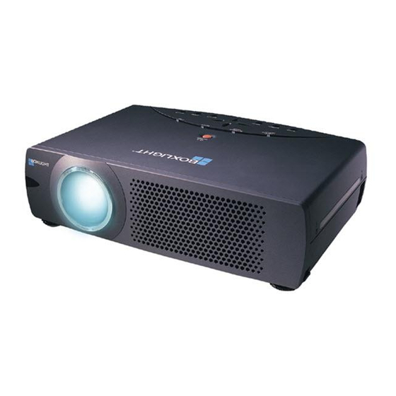
BOXLIGHT CP-12ta
NOTE: Match the Chassis No. on the unit's
Chassis No. MB3-CP-12ta00
back cover with the Chassis No. in the
Service Manual.
If the Original Version Service
Manual Chassis No. does not match
the
unit's,
additional
Literature is required.You must refer to
"Notices" to the Original Service
Manual prior to servicing the unit.
REFERENCE NO.
Service
SM
5110504-00
Advertisement
Table of Contents

Related Manuals for BOXLIGHT CP-12ta


Summary of Contents for BOXLIGHT CP-12ta
- Page 1 SERVICE MANUAL SERVICE MANUAL BOXLIGHT CP-12ta ORIGINAL VERSION Chassis No. MB3-CP-12ta00 NOTE: Match the Chassis No. on the unit’s back cover with the Chassis No. in the Service Manual. If the Original Version Service Manual Chassis No. does not match unit’s,...
-
Page 2: Table Of Contents
■ Contents ■ Safety Instructions ________________________________________________3 ■ Specifications ____________________________________________________4 ■ Adjustments after Parts Replacement ________________________________5 ■ Circuit Protections ________________________________________________6 ● Thermal switch ____________________________________________6 ● Interlock switch ____________________________________________6 ● Fuse ____________________________________________________6 ● Warning temperature and power failure protection __________________7 ■ Mechanical Disassemblies__________________________________________8 ■... -
Page 3: Safety Instructions
■ Safety Instructions SAFETY PRECAUTIONS WARNING: The chassis of this projector is isolated (COLD) from AC line by using the converter transformer. Primary side of the converter and lamp power supply unit circuit is connected to the AC line and it is hot, which hot circuit is iden- tified with the line ( ) in the schematic diagram. -
Page 4: Specifications
■ Specifications Projector Type Multi-media Projector Dimensions (W x H x D) 13.11” x 3.52” x 9.96” (333mm x 89.5mm x 253mm) Net Weight 9.5 lbs (4.3 kg) LCD Panel System 0.8” TFT Active Matrix type, 3 panels Panel Resolution 800 x 600 dots Number of Pixels 1,440,000 (800 x 600 x 3 panels) -
Page 5: Adjustments After Parts Replacement
■ Adjustments after Parts Replacement ● ❍ : Adjustment necessary : Check necessary Disassembly / Replaced Parts LCD/ Polarized glass Condenser Condenser Main Relay P. F. Power Prism Lens Lens-Out Board Lens-Out Board Board Ass’y Contrast Adjustment ● R-Contrast adjustment ●... -
Page 6: Circuit Protections
■ Circuit Protections This projector provides the following circuit protections to operate in safety. If the abnormality occurs inside the pro- jector, it will automatically turn off by operating one of the following protection circuits. ● Fuse Line Filter Board Fuse The fuse is located inside of the projector. -
Page 7: Warning Temperature And Power Failure Protection
Circuit Protections ● Warning temperature and power failure protection The projector will be automatically turned off when the internal temperature of the projector exceeds the normal oper- ating temperature, or the cooling fans stop, or the power supplies in the projector are failed. - If the TEMP WARNING indicator (red) is flashing, it may detect the abnormal temperature inside the projector. -
Page 8: Mechanical Disassemblies
■ Mechanical Disassemblies Mechanical disassemble should be made following procedures in numerical order. Following steps show the basic procedures, therefore unnecessary step may be ignored. Caution: The parts and screws should be placed exactly the same position as the original otherwise it may cause loss of performance and product safety. - Page 9 Mechanical Disassemblies AV, DVI, Temp Board and Speaker removal Remove 1 screw (M4x8) to release grounding wires. Pull the Rear Panel ass’y upward. Remove 4 screws (T3x6) and remove the AV Board. Remove 4 screws (T3x6) and remove the DVI Board. Remove 4 screws (T2.6x6) and remove the speaker.
- Page 10 Mechanical Disassemblies Lamp Ballast Unit removal Remove 1 screw (M3x4) and remove SW902, and then remove 1 screw (M3x6) and disconnect the Lamp Socket. Remove 2 screws (M3x6) to take the Lamp Ballast ass’y upward off. Remove 2 screws (T2x6) to take the isolation sheet off. Remove 4 screws (T3x6) to take the lamp ballast board off.
- Page 11 Mechanical Disassemblies Power Box Cover and Fans(FN901, FN906) removal Remove 4 screws (M3x12) to take the Fan(FN901) off. Remove 4 screws (M3x8) to take the Fan(FN906) off. Remove 3 screws (M3x6) to take the Power Box Cover upward off. FN906 Power box cover FN901 Fig.7...
- Page 12 Mechanical Disassemblies Optical Unit removal (2) Step from previous procedure. Remove 6 screws (M3x8) to take the Optical Unit upward upward off. To mount optical unit, mount optical unit first then mount the Lamp assembly and Lamp Cover. Optical unit Fig.8 Power and P.F.
- Page 13 Mechanical Disassemblies ⁄0 Fan (FN905) removal Remove 1 screw (M3x6) and take a Washer, Spring and Interlock Switch lever. Pull the Fan and duct ass’y upward, then remove the Interlock switch lever 2 screws (M3x6) to take the Fan (FN905) off. FN905 Fig.10 ⁄1...
-
Page 14: Optical Parts Disassemblies
■ Optical Parts Disassemblies Before taking this procedure, remove Cabinet Top and Main Board following to the “Mechanical Disassemblies”. Disassembly requires a 2.0mm hex wrench. Projection Lens removal Remove the Front Panel following to “Front Panel Removal” on “Mechanical Disassemblies”. Remove 4 screws (M3x10) to take the Projection Lens ass’y off. - Page 15 Optical Pats Disassemblies Condenser lens disassembly Remove 2 screws (M2.5x6) and pull the Condenser Lens ass’y upward. Remove 4 screws (M2x4) to take the Lens off from the holder. Condenser Lens Holder * Lens should be placed as the flat Fig.3- surface side comes to the holder side.
- Page 16 Optical Parts Disassemblies Relay Lens-Out disassembly Remove 2 screws (M2.5x6) and pull the Relay Lens-Out ass’y upward. Remove 2 screws (M2x4) to take the Lens off from the holder. Note: There is no mounting direction of the lens. Holder Relay Lens-Out Fig.5- Fig.5- Polarized Glass-In removal...
- Page 17 Optical Parts Disassemblies Polarized Glass-Out/Pre-Polarized Glass removal Remove 4 screws (M2.5x4) and take the LCD/Prism ass’y off upward from the optical unit. Remove each screw and take the glass off upward. Note: The G-LCD and B-LCD panels have a pre-polarized glass respective- ly as shown in Fig.7-2.
- Page 18 Optical Parts Disassemblies Locations and Directions Key No. Description When the optical parts in the optical unit mounting or assembling, the Mirror (W) parts must be mounted in the specified location and direction as Integrator lens (OUT) shown in figure below. Prism beam splitter (PBS) Dichroic mirror (B) Condenser lens (OUT)
-
Page 19: Lcd Panel/Prism Ass'y Replacement
■ LCD Panel/Prism Ass’y Replacement IMPORTANT NOTICE on LCD Panel/Prism Ass'y Replacement LCD panels used for this model can not be replaced separately. Do not disassemble the LCD Panel/Prism Ass’y. These LCD panels are installed with precision at the factory. When replacing the LCD panel, should be replaced whole of the LCD panels and prism ass’y at once. -
Page 20: Lamp Replacement
■ Lamp Replacement WARNING: ORDER REPLACEMENT LAMP - For continued safety, replace with a lamp assembly of the same type. Type No. Service Parts No. - Allow the projector to cool for at least 45 minutes before you open the POA-LMP53 610 303 5826 lamp cover. -
Page 21: Optical Adjustments
■ Optical Adjustments Before taking optical adjustments below, remove the Cabinet Top and Main Board following to the “Mechanical Disassemblies” Adjustments require a 2.0mm hex wrench and a slot screwdriver. When you adjust Condenser lens, Condenser lens-out or Relay lens adjustment, you need to disconnect some connectors and FPC cables of LCD panels on the main board. - Page 22 Optical Adjustments Condenser Lens adjustment Turn the projector on by a state of without FPC cables. Project only green light on the screen. Adjust the adjustment base of condenser lens assy to make color uniformity in green. 1) If the shading appears on the left or right of the screen as Green shown in Fig.2-1, loosen 2 screws with the 2.0mm hex driv-...
- Page 23 Optical Adjustments Condenser Lens-Out adjustment Turn the projector on by a state of without FPC cables. Project green and blue lights on the screen. Adjust the adjustment base of condenser lens-out assy to make color uniformity in cyan. 1) If the shading appears on the left or right of the screen as shown Cyan in Fig.3-1, loosen 1 screw with the 2.0mm hex driver, and...
- Page 24 Optical Adjustments Relay lens-Out adjustment Turn the projector on by a state of without FPC cables. Project all of lights on the screen. Adjust the adjustment base of relay lens assy to make color unifor- mity in white. 1) If the shading appears on the left or right of the screen as shown White in Fig.4-1, loosen 1 screw with the 2.0mm hex driver, and...
-
Page 25: Electrical Adjustments
■ Electrical Adjustments ● Service Adjustment Menu Operation To enter the service mode To enter the “Service Mode”, press and hold the MENU and IMAGE button on the projector at the same time for more than 3 seconds. The service menu appears on the screen as follows. To adjust service data Select the adjustment item no. -
Page 26: Circuit Adjustments
Electrical Adjustments ● Circuit Adjustments CAUTION: The each circuit has been made by the fine adjustment at factory. Do not attempt to adjust the follow- ing adjustments except requiring the readjustments in servicing otherwise it may cause loss of per- formance and product safety. - Page 27 Electrical Adjustments Signal Center adjustment Gain adjustment [PC] 1. Receive the 16-step grey scale computer signal with 1. Receive the 16-step gray scale computer signal with Computer [Analog RGB] mode. Computer [Analog RGB] mode. 2. Enter the service mode. 2. Enter the service mode. TP505R TP505R 3.
- Page 28 Electrical Adjustments Gain adjustment [Component] Gamma Gain adjustment [AV] 1. Receive the 16-step gray scale component video sig- 1. Receive the 16-step gray scale composite video sig- nal [480i] with Video [Y,Cr,Cb] mode. nal with Video [Video] mode. 2. Enter the service mode. 2.
- Page 29 Electrical Adjustments ⁄0 ⁄2 Signal Offset adjustment [PC] White Balance adjustment 1. Receive the 16-step gray scale computer signal with [PC WHITE BALANCE ADJUSTMENT] Computer [Analog RGB] mode. 1. Receive the 16-step gray scale computer signal with 2. Enter the service mode. Computer [Analog RGB] mode.
-
Page 30: Test Points And Locations
Electrical Adjustments Test Points and Locations ● MAIN BOARD TP6241 TP6221 TP6201 TP3501 TP3531 -30-... -
Page 31: Service Adjustment Data Table
Electrical Adjustments ● Service Adjustment Data Table These initial values are the reference data written from the CPU ROM to memory IC when replaced new memory IC. The adjust- ment items indicated with “✻” are required to readjust following to the “Electrical adjustments”. Other items should be used with the initial data value. - Page 32 Electrical Adjustments Initial Item No. Name Device YCbCr Video Detail NTSC V-Line Color Shading Correction Setting (B_OFFSET 4) CXD3526GG V-Line Color Shading Correction Setting (B_OFFSET 5) CXD3526GG V-Line Color Shading Correction Setting (B_OFFSET 6) CXD3526GG V-Line Color Shading Correction Setting (B_OFFSET 7) CXD3526GG V-Line Color Shading Correction Setting (B_OFFSET 8) CXD3526GG...
- Page 33 Initial Item No. Name Device YCbCr Video Detail NTSC Lamp use time in min. REDGAIN AD9884 GRNGAIN AD9884 BLUGAIN AD9884 REDOFST AD9884 GRNOFST AD9884 BLUOFST AD9884 CLDUR AD9884 CLPLACE AD9884 OverScan Expand Ratio (Vertical) 60Hz PIXEL Video and S-Video mode only. Expand Ratio (Horizontal) 60Hz PIXEL Position (Horizontal) 60Hz...
-
Page 34: Chassis Block Diagrams
■ Chassis Block Diagrams Chassis over view B-PANEL G-PANEL R-PANEL D0-7 A0-A17 TXD,RXD IC6301 SYNC-SW IC5351 INVERTER IC5341 G-SYNC IC5331 DVI-SW IC5321 PC/AV-SW IC5311 PC1/PC2-SW IC5001 AUDIO-AMP. IC001 AUDIO-SW D-SUB DVI-I AUDIO -34-... -
Page 35: Inputs & Video Signal Processing Stage
Chassis Block Diagrams Inputs & video signal processing stage IC8051 IC8061 IC8071 BUFFER BUFFER BUFFER IC6301 SYNC-SW <TC74LCX244> IC8001 IC8201 DVI-I/F IC3101 <> <THC63DV161> VIDEO DECIDER <VPC3230> IC5351 INVERTER IC5341 SYNC.SEP <BA7078> IC5331 IC5201 DVI-SW <TC4052> PC/AV RGB-SW <AN5870> IC5321 PC/AV-SW <BD7600>... -
Page 36: Lcd Panel Driving Stage
Chassis Block Diagrams LCD panel driving stage IC3561 IC441 IC431 IC421 IC411 IC401 BUFFER BUFFER BUFFER BUFFER LCD DRIVER <CXD3526> -36-... -
Page 37: Audio Signal Processing Circuit
Chassis Block Diagrams Audio signal processing circuit AV BOARD PC/AV_SW5 MUTE5 AUDIO-IN Q021 SP901 AUDIO-IN Q051 Q031 Q041 Q013 AUDIO Q014 Q011 MUTE5 Q012 K10T 21-22 19-20 17-18 D0-D7 MUTE: H D0-D7 PC: H AV: L PSCL MAIN BOARD VOL_CTL PSDA -37-... -
Page 38: Motor Driving Circuit
Chassis Block Diagrams Motor driving circuit FOCUS PSCL IC5551 FOCUS DRIVE FOCUS+,- <BA6287> PSDA ZOOM IC5501 11,12 D0-D7 ZOOM DRIVE <BA6287> ZOOM+,- MAIN BOARD POWER BOARD Logic Table of Drive ICs (IC5501,IC5551) Input Output Operation Forward drive Reverse drive Braking Mode Open Open Standby Mode -38-... -
Page 39: System Controls
Chassis Block Diagrams System controls IC7801 <M62392> IC1351 BUFFER IC1803 IC1804 IC1806 IC1813 IC1822 IC1823 <TC74LCX574> <TC74LCX574> <TC74LCX574> <TC74LCX574> <TC74LCX541> <TC74LCX541> IC301 SYSTEM CONTROL <PW164B-10> -39-... -
Page 40: Power Supply & Protection Circuit
Chassis Block Diagrams Power supply & protection circuit FAN CONTROL CIRCUIT Q65B Q65C Q662 15.5V AUDIO AUDIO AUDIO AUDIO 9VMCI 9VMCI 5V_SW POWER_FAIL FANDRIVE IC631 POWER OSC. <STR-Z5156> IC611 P.F.CONTROL <FA5502> IC1804 IC1813 IC1822 SW-OUT SW-OUT SW-IN IC301 SYSTEM CONTROL <PW161B-10>... - Page 41 Chassis Block Diagrams Fan controlcircuit FN901 D69D Q671 FN902 15.5V D69C Q67Q FN903 D67D Q67A D67Q IC671 D69B FN906 FN905 FN904 Q69A Q672 POWER_FAIL Q681 Q68Q D69A D68D Q68A D68Q IC681 Q682 Q66A POWER BOARD 13-14 19-20 21-22 11-12 IC1804 FANDRIVE I/O-SW SENSOR BOARD...
-
Page 42: Troubleshooting
■ Troubleshooting No Power This projector provides a function which can be specified a defective area simply by indicating the LEDs on the con- trol panel. Connect the AC cord and press the Power button once and then check the LED indication. - When all the LED indicators are not lighting, the symptom indicates that the primary power supply circuit does not operate properly. -
Page 43: No Picture
Troubleshooting No Picture Check following steps. No picture with all of Check signal processing stage and LCD driving stage; input sources Check RGB S&H signals at test points TP501B, TP502B, TP503G, TP504G, TP505R, TP506R. Check PSIG signals at test points TP3501 and TP3531. Check power supply circuit 15.5V SWD and peripheral circuit. - Page 44 Troubleshooting From previous page No picture with S-VIDEO Check AV source selecting stage; input source Check S-video signal (Y/C) on the AV board. Check IC2101, Video/S-Video-sw, and IC3101, Video decoder, and peripheral circuit. S/CV-SW signal (S-Video:H) is applied on pins 2, 7 and 12 of IC2101, output from pin 17 of IC1804.
-
Page 45: No Sound
Troubleshooting No Sound Check following steps. audio signal Check PC/AV-audio switching circuit. observed on the AUDIO- Check IC001, audio-sw IC, and peripheral circuit. PC/AV_SW5 OUT terminal? (PC:L) signal is applied on pin 10 of IC001 through Q041. MUTE5 signal (Mute:H) is applied on pin 9 of IC001 output from pin 12 of IC1803 through IC1351, buffer IC. -
Page 46: Control Port Functions
■ Control Port Functions ● System Control & I/O Port Table IC Ref. No Pin/Name Signal Name Function Note IC301 PortA0 ROMWEL For ICE PortA1 ROMWEH For ICE PortA2 BOOTWE For ICE PortA3 DDC_CK NVRAM I2C CLK for DDC PortA4 5V_SW Power ON/OFF MainPower-ON:High... - Page 47 Control Port Functions IC Ref. No Pin/Name Signal Name Function Note Not used Not used Not used KEY_WE Not used DSINV_SW Not used IC1822 Main Key Switch Main Key Switch Main Key Switch Main Key Switch M2/SEL0 Mouse Selection 0 M2/SEL1 Mouse Selection 1 LAMP_ERR...
-
Page 48: Waveform
■ Waveform VIDEO-IN <TPV3143> HS signal <TPHS> VS signal <TPVS> DHS signal <TPDHS> DVS signal <TPDVS> S&H-B <TP501B/TP502B> S&H-G <TP503G/TP504G> S&H-R <TP505R/TP506R> PSIG <TP3501> PSIG <TP3551> -48-... -
Page 49: Cleaning
■ Cleaning After long periods of use, dust and other particles will accumulate on the LCD panel, prism, mirror, polarized glass, lens, etc., causing the picture to darken or color to blur. If this occurs, clean the inside of optical unit. Remove dust and other particles using air spray. -
Page 50: Ic Block Diagrams
■ IC Block Diagrams ● AD8075 <Selector, IC201> ● AD8183ARU <Selector, IC1201> ● AN7513 <Audio-Amp, IC5001> -50-... - Page 51 IC Block Diagrams ● AD9884AKS <A/D, IC8201> ● AN5870SB <RGB-SW, IC5201> -51-...
- Page 52 IC Block Diagrams ● AV9155C <Clock Driver, IC1301> 2XCPU OUTPUT SCLK20-22 BUFFERS CLOCK 14.318MHz crystal REFERENCE CLOCK 14.318MHz KBCLK 14.318MHz OUTPUT PERIPHERAL BUSCLK BUFFERS CLOCK FDCLK COMMCLK POWER-DOWN AGND ● BA6287 <Motor Drive, IC5501, IC5551, IC5561> -52-...
- Page 53 IC Block Diagrams ● BA7078 <Sync Separator, IC5341> ● CXA7000R <D/A, S/H-LCD Driver, > IC501, IC1501, IC530, IC1531, IC561, IC1561 -53-...
- Page 54 IC Block Diagrams ● CXD3526GG <LCD Driver, Timing Generator, IC401> ● FA5502 <P.F. Control, IC611> -54-...
- Page 55 IC Block Diagrams ● LA7217 <Sync Separator, IC5361> ● M62392 <D/A, IC3561> -55-...
- Page 56 IC Block Diagrams ● M62393 <D/A, IC281, IC7801> ● NJM2284M <Switch, IC2101> -56-...
- Page 57 IC Block Diagrams ● PW164B-10 <System Control & Scan Converter, IC301> ● STR-Z2156 <Power Switching Control, IC631> -57-...
- Page 58 IC Block Diagrams ● VPC3230D <Video Decoder, IC3101> Analog Adaptive Colour Mixer Y 2D Scaler Output YOUT VIN1 Comb Decoder Formatter Front-end Cr,Cb Filter VIN2 NTSC ITU-R 656 VIN3 ITU-R 601 YCOE NTSC SECAM Contrast VIN4 2XADC Memory Brightness FIFO Saturation Peaking Control...
-
Page 59: Service Parts List
■ Electrical Parts List MB3-CP-12ta00 Product safety should be considered when a component replacement is made in any area of a projector. Components indicated by a ! mark in this parts list and the circuit diagram show components whose value have spe- cial significance to product safety. - Page 60 MB3-CP-12ta00 Electrical Parts List Note: Parts order must contain Chassis No., Part No., and Descriptions. ● OUT OF CIRCUIT BOARD A901 Key SW Board Ballast Board P.F. Board F601 Fuse Main Board Line Filter Board RC Front Board Power Board DVI Board Temp Board AV Board...
- Page 61 MB3-CP-12ta00 Electrical Parts List Key No. Part No. Description Key No. Part No. Description 405 173 9803 TR 2SC3928A1R ASSEMBLIED BOARDS 405 173 9902 TR 2SC3928A1S Q014 405 014 4509 TR 2SC2412K T146 R 610 301 3954 ASSY,PWB,AV MA3A 405 014 4608 TR 2SC2412K T146 S 610 301 3961 ASSY,PWB,DVI MA3A...
- Page 62 MB3-CP-12ta00 Electrical Parts List Key No. Part No. Description Key No. Part No. Description 405 015 8902 TR 2SC2812-L7-TB 405 163 1602 TR 2SC2812N-L6-TB0 405 163 1602 TR 2SC2812N-L6-TB0 405 163 1701 TR 2SC2812N-L7-TB0 405 163 1701 TR 2SC2812N-L7-TB0 405 173 9803 TR 2SC3928A1R 405 173 9803 TR 2SC3928A1R...
- Page 63 MB3-CP-12ta00 Electrical Parts List Key No. Part No. Description Key No. Part No. Description C012 403 175 4802 NP-ELECT 10U M R1003 401 113 4402 MT-GLAZE 75 JA 1/16W C021 403 164 0204 CERAMIC 0.1U Z R1004 401 113 4402 MT-GLAZE 75 JA 1/16W C031...
- Page 64 MB3-CP-12ta00 Electrical Parts List Key No. Part No. Description Key No. Part No. Description R212 401 105 0405 MT-GLAZE 100 JA 1/16W D012 407 149 0807 DIODE 1SS355-TE-17 R213 401 105 0504 MT-GLAZE 1K JA 1/16W D1001 407 179 0501 ZENER DIODE UDZ6.2B-TE-17 R214 401 105 0405...
- Page 65 MB3-CP-12ta00 Electrical Parts List Key No. Part No. Description Key No. Part No. Description 405 173 9605 TR 2SA1235A1E D3071 407 187 8209 ZENER DIODE UDZ12B-TE-17 405 173 9704 TR 2SA1235A1F D3072 407 187 8209 ZENER DIODE UDZ12B-TE-17 Q3072 405 134 5905 TR 2SA1037AK-T146-R MISCELLANEOUS 405 147 2205...
- Page 66 MB3-CP-12ta00 Electrical Parts List Key No. Part No. Description Key No. Part No. Description 405 015 8704 TR 2SC2812-L6-TB Q5302 405 014 4509 TR 2SC2412K T146 R 405 015 8902 TR 2SC2812-L7-TB 405 014 4608 TR 2SC2412K T146 S 405 163 1602 TR 2SC2812N-L6-TB0 405 015 8704 TR 2SC2812-L6-TB...
- Page 67 MB3-CP-12ta00 Electrical Parts List Key No. Part No. Description Key No. Part No. Description 405 015 8902 TR 2SC2812-L7-TB IC1302 409 487 5704 IC TC7SZ125FU 405 163 1602 TR 2SC2812N-L6-TB0 IC1303 409 501 9107 IC ICS512MT 405 163 1701 TR 2SC2812N-L7-TB0 IC1304 409 350 2908 IC TC7W126FU-(TE12L)
- Page 68 MB3-CP-12ta00 Electrical Parts List Key No. Part No. Description Key No. Part No. Description IC711 409 347 5400 IC M51204FP-600C C2522 403 164 0204 CERAMIC 0.1U Z IC7201 409 528 6608 IC LC749400W C2524 403 164 0204 CERAMIC 0.1U Z IC721 409 400 9208 IC TC7SET32FU-(TE85L)
- Page 69 MB3-CP-12ta00 Electrical Parts List Key No. Part No. Description Key No. Part No. Description C3143 403 205 2808 CERAMIC 0.047U K C427 403 164 0204 CERAMIC 0.1U Z C3144 403 325 6304 CERAMIC 0.22U K C428 403 164 0204 CERAMIC 0.1U Z C3146 403 215 0900...
- Page 70 MB3-CP-12ta00 Electrical Parts List Key No. Part No. Description Key No. Part No. Description C536 403 229 3508 ELECT 100U M C581 403 164 0204 CERAMIC 0.1U Z 403 335 0408 ELECT 100U M C6201 403 283 6309 CERAMIC 1U Z C5361 403 364 5801 CERAMIC...
- Page 71 MB3-CP-12ta00 Electrical Parts List Key No. Part No. Description Key No. Part No. Description C8021 403 155 1500 CERAMIC 180P J 645 037 0830 R-NETWORK 47X4 1/32W C8022 403 169 2807 CERAMIC 330P J RB511 645 034 5050 R-NETWORK 22X4 1/32W C8023 403 157 3601 CERAMIC...
- Page 72 MB3-CP-12ta00 Electrical Parts List Key No. Part No. Description Key No. Part No. Description RB8254 645 036 0985 R-NETWORK 47X4 1/32W R1837 401 105 0603 MT-GLAZE 10K JA 1/16W 645 037 0830 R-NETWORK 47X4 1/32W R1838 401 105 7909 MT-GLAZE 0.000 ZA 1/16W RB8256 645 036 0985...
- Page 73 MB3-CP-12ta00 Electrical Parts List Key No. Part No. Description Key No. Part No. Description R3108 401 105 0405 MT-GLAZE 100 JA 1/16W R3581 401 105 5301 MT-GLAZE 4.7K JA 1/16W R3109 401 105 0405 MT-GLAZE 100 JA 1/16W R3582 401 105 2904 MT-GLAZE 22K JA 1/16W R3110...
- Page 74 MB3-CP-12ta00 Electrical Parts List Key No. Part No. Description Key No. Part No. Description R416 401 105 0306 MT-GLAZE 10 JA 1/16W R5282 401 105 1303 MT-GLAZE 15 JA 1/16W R417 401 105 7909 MT-GLAZE 0.000 ZA 1/16W R5283 401 105 5400 MT-GLAZE 47K JA 1/16W R418...
- Page 75 MB3-CP-12ta00 Electrical Parts List Key No. Part No. Description Key No. Part No. Description R546 401 105 2607 MT-GLAZE 22 JA 1/16W R6356 401 105 7909 MT-GLAZE 0.000 ZA 1/16W R547 401 105 7909 MT-GLAZE 0.000 ZA 1/16W R6357 401 105 7909 MT-GLAZE 0.000 ZA 1/16W R548...
- Page 76 MB3-CP-12ta00 Electrical Parts List Key No. Part No. Description Key No. Part No. Description R7803 401 105 0405 MT-GLAZE 100 JA 1/16W R9308 401 105 0306 MT-GLAZE 10 JA 1/16W R7804 401 105 0405 MT-GLAZE 100 JA 1/16W R9309 401 105 7909 MT-GLAZE 0.000 ZA 1/16W R7806...
- Page 77 MB3-CP-12ta00 Electrical Parts List Key No. Part No. Description Key No. Part No. Description COIL X1331 645 037 9352 OSC,CRYSTAL 24.000MHZ X3121 645 034 6118 OSC,CRYSTAL 20.250MHZ L1301 645 020 1776 INDUCTOR,3.3U M X3801 645 053 9114 OSC,CERAMIC 6.000MHZ L1302 401 035 4108 MT-GLAZE 0.000 ZA...
- Page 78 MB3-CP-12ta00 Electrical Parts List Key No. Part No. Description Key No. Part No. Description 405 173 9902 TR 2SC3928A1S 405 015 8704 TR 2SC2812-L6-TB Q651 405 014 4509 TR 2SC2412K T146 R 405 015 8902 TR 2SC2812-L7-TB 405 014 4608 TR 2SC2412K T146 S 405 163 1602 TR 2SC2812N-L6-TB0...
- Page 79 MB3-CP-12ta00 Electrical Parts List Key No. Part No. Description Key No. Part No. Description R5505 401 105 5301 MT-GLAZE 4.7K JA 1/16W R672 401 105 4007 MT-GLAZE 330 JA 1/16W R5506 401 105 5301 MT-GLAZE 4.7K JA 1/16W R673 401 230 4705 MT-GLAZE 680 JA R5551...
- Page 80 MB3-CP-12ta00 Electrical Parts List Key No. Part No. Description Key No. Part No. Description D652B 411 174 4808 SCR S-TPG PAN+SWW 3X8 C62J 403 169 2807 CERAMIC 330P J D653 407 190 4106 DIODE SFPL-52V C62K 403 323 3602 CERAMIC 0.047U K D654 407 209 1201...
- Page 81 MB3-CP-12ta00 Electrical Parts List Key No. Part No. Description Key No. Part No. Description C601 404 081 4702 MT-POLYEST 0.22U M 275V C602 404 081 4702 MT-POLYEST 0.22U M 275V C603 404 081 4702 MT-POLYEST 0.22U M 275V C604 404 081 4702 MT-POLYEST 0.22U M 275V...
- Page 82 MB3-CP-12ta00 Electrical Parts List Key No. Part No. Description Key No. Part No. Description -82-...
-
Page 83: Mechanical Parts List
■ Mechanical Parts List MB3-CP-12ta00 Note: Parts order must contain Chassis No., Part No., and Descriptions. ● CABINET PARTS -83-... - Page 84 MB3-CP-12ta00 Mechanical Parts List ● Optical PARTS -84-...
- Page 85 MB3-CP-12ta00 Mechanical Parts List 67 (Red) 68 (Green) 69 (Blue) -85-...
- Page 86 MB3-CP-12ta00 Mechanical Parts List 53-a (Red) 53-b (Green) 53-c (Blue) 53-d (Green/Blue) -86-...
- Page 87 MB3-CP-12ta00 Mechanical Parts List 52-a -87-...
- Page 88 MB3-CP-12ta00 Mechanical Parts List -88-...
- Page 89 MB3-CP-12ta00 Mechanical Parts List Key No. Part No. Description Key No. Part No. Description CABINET PARTS OPTICAL PARTS 610 292 6972 BUTTON CONTROL-MS6B 645 046 8483 ASSY,PRISM(PBS) 610 292 6996 BUTTON ZOOM-MS6B 645 057 1466 ASSY,LENS,PROJECTION 610 292 5654 BUTTON POWER-MS6A (Including Key No.52-a) 610 292 7061 CABINET TOP-MS6L...
- Page 90 Boxlight 19332 Powder Hill Place Poulsbo, WA 98370-7407 USA www.boxlight.com U.S. and Canada 800-762-5757 International 360-779-7901 (MB3E) Jun 2003 BB 10 Printed in Japan...
- Page 91 CP-12ta MB3-CP-12ta00 These schematic diagrams and printed wiring board drawings are part of the service manual original for chassis No. MB3-CP-12ta00 model CP-12ta. File with the service manual No. SM5110504-00. Note: All the information of part numbers and values indicated on these diagrams are at the beginning of production.
-
Page 92: Parts Description And Reading In Schematic Diagram
■ Parts description and reading in schematic diagram MB3-CP-12ta00 1. The parts specification of resistors, capacitors and Resistor Reading coils are expressed in designated code. Please check Example 1/2 D J 10K B the parts description by the following code table. 2. - Page 93 ■ Pin description of diode, transistor and IC MB3-CP-12ta00 ● Diode ● Diode K: Cathode A: Anode ● Transistor/FET ● Transistor/FET C: Collector D: Drain B: Base G: Gate Index E: Emitter S: Source C1 C2 C1 C2 ● IC ●...
- Page 94 Diagrams & Drawings (MB3E)
-
Page 95: Schematic Diagrams
■ Schematic Diagrams LINE FILTER TERMOSTAT INTER LOCK AC CORD (SET TO OPEN 1AV4W11B AT 100+/-5C) SW902 00800 LF901 SW904 U20B30101 K903S C602 L601 C603 C604 K901S S10B3370N AC100-120V (LIVE) C601 L602 S10B3590N J11B F601 275GM 275GM 275GM J11B VA601 R601 275GM F35B... - Page 96 K10V J11MD400G PC1-R PC1-R K10V_39 C202 C201 PC1-G PC1-G 25KZ 25KZ K10V_37 PC1-B K10V_35 PC2-B R1001 R1003 Q201 R1081 C1001 IN2_R R1002 R1004 C200 RX2+ RX2+ 6.3EM220WM K10E_2 K10V_29 :6.3EM220F1 K10E_1 RX2- RX2- K10V_27 D1001 R1013 R201 1/16 1/16GJ R1082 6.2B GZ0C R200...
- Page 97 J10ML400G K3V_39 PC1-R K3V_37 PC1-G (IC6301 15P) ADHS PC1-B K3V_35 ADCLK (IC6351 12P) L8203 C8214 C8216 L2PD2R2MG 25KZ0.1 6.3EM100 RB8251 POWER-FAIL GQFZ (WM:F1) R1EB4704G: D5281 K3V_29 3.3VD R1JA4704G 1SS355 RX2+ C8217 K3V_27 POWER_FAIL 25KZ0.1 RX2- GQFZ IC5281 K3V_23 PC1/PC2-SW5 R5284 RX1+ SI-3012LU-TL R8218...
- Page 98 L8051 L2PD2R2MG IC7256 (IC301 222P) GFBK 3.3V R7273 1/16GZ0C TC7S66FU DPC_ON C8051 3.3VS 6.3EM100 (WM:F1) R7288 RB8051 1/16GZ0C DPC_ON D_CR0 R7261 R7275 D_CR1 C7275 1/16GJ IC301 D_CR2 SYSTEM (IC301 25P) PDEN R7262 R7263 D_CR3 1/16GZ0C 1/16GZ0C RB8014 RB8013 RB8012 RB8011 C8053 (IC8201 41P) COASTOUT...
- Page 99 FAN.SENS J10QY400G J10EG060G K8S_1 K8S_2 K8E_1 K8S_3 K8S_4 TEMP ZOOM_- ZOOM_+ K8E_2 K8S_5 K8S_6 IC8801 FOCUS_- FOCUS_+ LAMP_BST_SW “K48E” K8E_3 K8S_7 SDA1_5 R8801 LM76CHMX-5 R8803 1/16GJ 1/16GJ K8S_9 LAMP_BST_SW FANDRIVE 10KC K8E_5 J10EZ SCL1_5 K8S_11 200G FANDRIVE IC5641 C8803 POWER_FAIL K8S_13 25KZ0.1 POWER_FAIL...
- Page 100 TP801 IC1801 J30B 1640G TC7SH04FU; L1301 C1301 C1303 SN74AHC1G04HDCKR L2A7 C1302 3.3VS 25KZ 25KZ 3R3MG 470D GQFZ GQFZ 3.3VS TP802 J30B C1802 3.3VS 1640G (IC301 135P) IC1802 25KZ GQFZ L1302 TC7W00FU 1/8GZ000 C807 C1801 R802 10KZ1U 10KZ 1/16GJ GQFZ 10KC GQFZ R1309 1/16GJ...
- Page 101 C515 C516 10KZ1U 6.3EM C513 GQFZ 330D 25KZ0.1 GQFZ 15.5V C517 D2601 6.3KK L502 2.2GQ 1SS355 L2A9R47MG (IC7801 5P) B_VREF Q2601 R506 VCOM_B 2SA1203Y R519 C511 R512 R511 R513 25KZ0.1 2.5VS 2.5VD POWER_FAIL 1/16GZ 1/16GZ Q501 POWER_FAIL GQFZ R2561 R2563 R2564 C2561 C2562...
- Page 102 SCH_PK7AA...
-
Page 103: Printed Wiring Board Diagrams
■ Printed Wiring Board Diagrams ! CAUTION This projector is isolated from AC line by using the internal converter transformer. Please pay attention to the following notes in servicing 1. Do not touch the part on hot side (primary circuit) or both parts on hot and cold sides (secondary circuit) at the same time. - Page 104 MAIN (SIDE:A) P.F (SIDE:A) INTER LOCK LAMP BALLAST “A901” SW “SW904” R5324 R1201 R1208 C5312 C5326 Q5302 R1202 C1209 IC5321 R1203 R5316 Q5301 C1203 Q8002 D5321 R1211 C5281 R5332 D5324 R1212 D5281 C5323 R1213 TP12E R8005 Q7601 R5326 R5322 IC5311 C1202 C5223 R5282...
- Page 105 MAIN (SIDE:B) P.F (SIDE:B) R614 FB613 DVI “K10W” DVI “K10V” AV “K10Y” AV “K10T” AV “K10U” PTH611 R613 C612 DB611 Q611 D614 TSW611 R62L SP901 R5317 C5311 C5321 C5325 R5306 R5307 C2101 C2102 C8101 C5224 R62P C3874 C5322 C3873 IC8001 R5318 C5207 C9791...
- Page 106 POWER (SIDE:A) POWER (SIDE:B) D631 C642 C642 T651 R634 C639 D653 C653 C653 R635 R636 P.F. “K6E” IC651 PC642 C694 R691 C656 R657 R656 C659 C693 PC641 R641 D634 R661 Q641 PC643 R643 R640 C661 C686 C65F C692 C691 C65G EXHAUST FAN R662 L695...
- Page 107 KEY SW (SIDE:A) LINE FILTER (SIDE:A) MAIN “K8A” ON-OFF L601 F601 TYPE: 215004 T4AH 250V 1AA4B10C SW6801 3250C_B F601A LIVE 1AA4B10C3370A K68A SW902 D2863 A SIDE SW904 LF901 D2862 D2864 NEUT LAMP REPLACE WARNING TEMP. (YELLOW) READY(GREEN) (RED) C603 D2861 POWER LAMP C602 C601...
Need help?
Do you have a question about the CP-12ta and is the answer not in the manual?
Questions and answers