Table of Contents
Advertisement
www.proform.com
Model No. PFTL99215.1
Serial No.
Write the serial number in the space
above for reference.
Serial Number
Decal
ACTIVATE YOUR
WARRANTY
To register your product and
activate your warranty today,
go to www.proformservice.com/
registration.
CUSTOMER CARE
For service at any time, go to
www.proformservice.com.
Or call 1-888-533-1333
Mon.–Fri. 6 a.m.–6 p.m. MT
Sat. 8 a.m.–12 p.m. MT
Please do not contact the store.
CAUTION
Read all precautions and instruc-
tions in this manual before using
this equipment. Save this manual
for future reference.
USER'S MANUAL
Advertisement
Table of Contents

Subscribe to Our Youtube Channel
Related Manuals for ProForm power ZT10


Summary of Contents for ProForm power ZT10
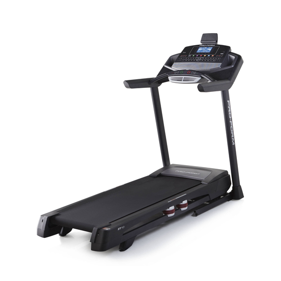
- Page 1 Model No. PFTL99215.1 USER’S MANUAL Serial No. Write the serial number in the space above for reference. Serial Number Decal ACTIVATE YOUR WARRANTY To register your product and activate your warranty today, go to www.proformservice.com/ registration. CUSTOMER CARE For service at any time, go to www.proformservice.com.
-
Page 2: Table Of Contents
Bluetooth SIG, Inc. and are used under license. IOS is a trademark or registered trademark of Cisco in the U.S. and other countries and is used under license. PROFORM is a registered trademark of ICON Health & Fitness, Inc. -
Page 3: Important Precautions
5. The treadmill is intended for home use only. purchase a surge suppressor, see your local Do not use the treadmill in any commercial, PROFORM dealer, call the telephone number rental, or institutional setting. on the front cover of this manual, or see your local electronics store. - Page 4 19. Always stand on the foot rails when starting 26. When folding or moving the treadmill, make or stopping the walking belt. Always hold the sure that the storage latch is holding the handrails while using the treadmill. frame securely in the storage position. 20.
- Page 6 STANDARD SERVICE PLANS...
-
Page 7: Before You Begin
BEFORE YOU BEGIN Thank you for selecting the revolutionary reading this manual, please see the front cover of this PROFORM ZT10 treadmill. The ZT10 treadmill offers manual. To help us assist you, please note the product ® an impressive selection of features designed to make model number and serial number before contacting us. -
Page 8: Part Identification Chart
PART IDENTIFICATION CHART Use the drawings below to identify small parts used for assembly. The number in parentheses below each draw- ing is the key number of the part, from the PART LIST near the end of this manual. The number following the key number is the quantity used for assembly. -
Page 9: Assembly
ASSEMBLY • To hire an authorized service technician to • Left parts are marked “L” or “Left” and right parts assemble the treadmill, call 1-800-445-2480 are marked “R” or “Right.” • Assembly requires two persons. • To identify small parts, see page 8. •... - Page 10 2. Make sure that the power cord is unplugged. Remove the tie securing the Upright Wire (81) to the front of the Base (94). Next, identify the Right Upright (90). Have a sec- ond person hold the Right Upright near the Base (94).
- Page 11 4. Hold the Right Upright (90) against the Base (94). Make sure not to pinch the Upright Wire (81). Next, hold a Wheel (97) inside the Base (94), and insert a 3/8" x 1 3/4" Screw (62) with a 3/8" Star Washer (13) through the Base and the Wheel as shown;...
- Page 12 6. Hold the Right Handrail (87) near the Right Upright (90). Insert the Upright Wire (81) through the Right Handrail as shown, and then remove the wire tie (A) from the Upright Wire. Next, attach the Right Handrail (87) to the Right Upright (90) with two 5/16"...
- Page 13 8. Set the console assembly (F) face down on a soft surface to avoid scratching the console assembly. Remove and save the four 5/16" x 1/2" Screws (4). 9. Set the console assembly (F) on the Left and Right Handrails (86, 87). Make sure not to pinch any wires (G, 81).
- Page 14 10. Attach the console assembly (F) to the Left and Right Handrails (86, 87) with four #10 x 3/4" Screws (9) and four #10 Star Washers (5) as shown; start all four Screws, and then tighten them. 11. See the inset drawing. Connect the Upright Wire (81) to the console wire (G).
- Page 15 12. Attach the Right Handrail Cover (92) to the Right Handrail (87) with three #8 x 1/2" Screws (1); do not overtighten the Screws. Attach the Left Handrail Cover (79) to the Left Handrail (86) in the same way. 13. Slide the Left Bottom Handrail Cover (85) up against the Left Handrail Cover (79), and attach the Left Bottom Handrail Cover with two #8 x 1/2"...
- Page 16 14. Note: If the treadmill is assembled on a smooth surface, it may roll forward during this step. Raise the Frame (56) to the upright position. Brackets IMPORTANT: Do not raise the Frame past the vertical position. Have a second person hold the Frame until step 16 is completed.
- Page 17 16. Remove the 5/16" Nut (12) and the 5/16" x 2 1/4" Bolt (3) from the bracket on the Latch Crossbar (38). Align the upper end of the Storage Latch (53) with the bracket on the Latch Crossbar (38), and insert the 5/16" x 2 1/4" Bolt (3) through the bracket and the Storage Latch.
- Page 18 18. Attach the Tablet Holder (110) to the back of the console assembly (F) with four #8" x 1/2" Machine Screws (115); start all four Machine Screws, and then tighten them. Be careful not to overtighten the Machine Screws. 19. Make sure that all parts are properly tightened before you use the treadmill. If there are sheets of plastic on the treadmill decals, remove the plastic.
-
Page 19: How To Use The Treadmill
HOW TO USE THE TREADMILL HOW TO CONNECT THE POWER CORD nominal 120-volt circuit capable of carrying 15 or more amps. To avoid overloading the circuit, do Use a Surge Suppressor not plug other electrical devices, except for low- power devices such as cell phone chargers, into Your treadmill, like other electronic equipment, can be the surge suppressor or into an outlet on the same damaged by sudden voltage changes in your home’s... - Page 20 CONSOLE DIAGRAM FEATURES OF THE CONSOLE race against other iFit users, and access many other features. To purchase an iFit module at any time, go The treadmill console offers an impressive array of to www.iFit.com or call the telephone number on features designed to make your workouts more effec- the front cover of this manual.
- Page 21 HOW TO TURN ON THE POWER HOW TO USE THE MANUAL MODE IMPORTANT: If the treadmill has been exposed to 1. Insert the key into the console. cold temperatures, allow it to warm to room tem- perature before you turn on the power. If you do See HOW TO TURN ON THE POWER at the left.
- Page 22 4. Change the incline of the treadmill as desired. The Incline tab will show a profi le of the incline set- tings of the workout. A new segment will appear at To change the incline of the treadmill, press the the end of each minute.
- Page 23 6. Measure your heart rate if desired. 8. When you are finished exercising, remove the key from the console. You can measure your heart rate using either the handgrip heart rate monitor or a compatible heart Step onto the foot rails, press the Stop button, and rate monitor.
- Page 24 3. Start the workout. Note: The calorie goal is an estimate of the number of calories that you will burn during Press the Start button or the Speed increase button the workout. The actual number of calories to start the workout. A moment after you press the that you burn will depend on various factors button, the treadmill will automatically adjust to the such as your weight.
- Page 25 HOW TO USE A SET-A-GOAL WORKOUT 5. Measure your heart rate if desired. 1. Insert the key into the console. See step 6 on page 23. See HOW TO TURN ON THE POWER on page 21. 6. Turn on the fan if desired. 2.
- Page 26 To stop the workout at any time, press the Stop 4. Select an iFit workout. button. The time will begin to fl ash in the display. To resume the workout, press the Start button or To select an iFit workout, press one of the iFit but- the Speed increase button.
- Page 27 THE OPTIONAL CHEST HEART RATE MONITOR THE INFORMATION MODE Whether your The console features an information mode that keeps goal is to track of treadmill information and allows you to person- burn fat or to alize console settings. strengthen your cardiovascular 1.
- Page 28 CONTRAST LVL—Press the Incline increase and HOW TO USE THE TABLET HOLDER decrease buttons to adjust the contrast level of the display. You can use your tablet to browse media while you exercise. Place your tablet on the tablet holder and let If a module is connected, you may also select the the tablet holder hold your tablet in place.
-
Page 29: How To Fold And Move The Treadmill
HOW TO FOLD AND MOVE THE TREADMILL HOW TO FOLD THE TREADMILL HOW TO MOVE THE TREADMILL To avoid damaging the treadmill, adjust the incline Before moving the treadmill, fold it as described at the to zero before you fold the treadmill. Then, remove left. -
Page 30: Maintenance And Troubleshooting
MAINTENANCE AND TROUBLESHOOTING MAINTENANCE SYMPTOM: The power turns off during use Regular maintenance is important for optimal perfor- a. Check the power switch (see drawing c at the left). mance and to reduce wear. Inspect and properly tighten If the switch has tripped, wait for fi ve minutes and all parts each time the treadmill is used. - Page 31 SYMPTOM: The walking belt slows when walked on SYMPTOM: The walking belt is off-center or slips when walked on a. Use only a surge suppressor that meets all of the specifi cations described on page 19. a. If the walking belt is off-center, fi rst remove the key and UNPLUG THE POWER CORD.
-
Page 32: Exercise Guidelines
EXERCISE GUIDELINES Burning Fat—To burn fat effectively, you must exer- WARNING: cise at a low intensity level for a sustained period of Before beginning this time. During the first few minutes of exercise, your or any exercise program, consult your physi- body uses carbohydrate calories for energy. - Page 33 SUGGESTED STRETCHES The correct form for several basic stretches is shown at the right. Move slowly as you stretch —never bounce. 1. Toe Touch Stretch Stand with your knees bent slightly and slowly bend forward from your hips. Allow your back and shoulders to relax as you reach down toward your toes as far as possible.
-
Page 34: Part List
PART LIST Model No. PFTL99215.1 R0915A Key No. Qty. Description Key No. Qty. Description #8 x 1/2" Screw 3/8” Plastic Bushing #8 x 3/4" Screw 3/8” Washer 5/16" x 2 1/4" Bolt Storage Latch 5/16" x 1/2" Screw Drive Motor #10 Star Washer Motor Belt 5/16"... - Page 35 Key No. Qty. Description Key No. Qty. Description Base Pad #8 x 3/4" Truss Head Screw Tablet Holder Left Rear Cap Right Inner Base Cover Right Rear Cap Left Front Cushion Top 1/4" Nut Right Front Cushion Top Console Clamp 1/4"...
-
Page 36: Exploded Drawing
EXPLODED DRAWING A Model No. PFTL99215.1 R0915A... - Page 37 EXPLODED DRAWING B Model No. PFTL99215.1 R0915A...
- Page 38 EXPLODED DRAWING C Model No. PFTL99215.1 R0915A...
- Page 39 EXPLODED DRAWING D Model No. PFTL99215.1 R0915A...
-
Page 40: Ordering Replacement Parts
ORDERING REPLACEMENT PARTS To order replacement parts, please see the front cover of this manual. To help us assist you, be prepared to provide the following information when contacting us: • the model number and serial number of the product (see the front cover of this manual) •...
Need help?
Do you have a question about the power ZT10 and is the answer not in the manual?
Questions and answers