Table of Contents
Advertisement
Quick Links
Download this manual
See also:
Operating Manual
Advertisement
Table of Contents

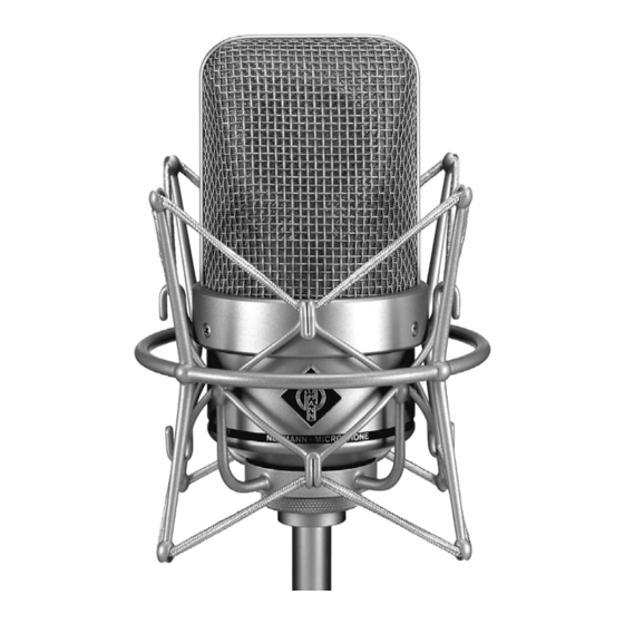
Summary of Contents for Neumann.Berlin M 150 Tube
- Page 1 Bedienungsanleitung Operating Instructions M 150 Tube georg neumann gmbh · ollenhauerstr. 98 · 13403 berlin · germany tel +49 (0)30 / 41 77 24-0 · fax -50 · headoffice@neumann.com · www.neumann.com...
-
Page 2: Table Of Contents
N 149 A power sup- gerät N 149 A gespeist. ply unit. Die Einsprechrichtung des M 150 Tube wird durch The front of the M 150 Tube microphone is desig- das Neumann-Emblem gekennzeichnet. nated by the Neumann logo. -
Page 3: Das Kondensatormikrofon M 150 Tube
üblicher, d.h. zylindrischer, Bauweise ist beim tion, the transducer of the M 150 Tube is built fl ush M 150 Tube der Wandler bündig in die Oberfl äche into the surface of a sphere 40 mm in diameter. In einer Kugel mit 40 mm Durchmesser eingebaut. -
Page 4: Einige Zusatzinformationen Zur Schaltungstechnik Im M 150 Tube
The transformerless circuit rakter, und zwar pegel-, frequenz- und lastabhängig. Die transformatorlose Schaltungstechnik sorgt – wie design of the M 150 Tube provides a very good com- ein Übertrager – für eine gute Unsymmetriedämp- mon mode rejection factor just like a transformer. -
Page 5: Inbetriebnahme
Despite this 10 dB und schließt Resteinfl üsse der nachgeschal- amplifi cation the dynamic range of the M 150 Tube teten Elektronik auf die Signalübertragung des Mi- remains very wide as the microphone delivers a krofons gänzlich aus. -
Page 6: Ausführungsform Und Beschaltung Des Mikrofon- Und Netzgeräteausgangs
External phantom power, if present, does not de- Wird eine externe Phantomspeisung an- oder abge- tract from the performance of the M 150 Tube. If schaltet, ergibt sich kurzzeitig ein leicht erhöhter an external phantom power source is switched on Eigengeräuschpegel. -
Page 7: Mikrofonkabel
Stift 2 eine positive Spannung auf. diaphragm produces a positive voltage at pin 2. 2.4 Mikrofonkabel 2.4 Microphone Cables Für das M 150 Tube stehen folgende Kabel zur Ver- The following cables are available for the fügung: M 150 Tube: KT 8 (10 m) ... - Page 8 Pin 2 ist also die „heiße Phase“, und Pin 3 muss für So pin 2 is the “hot phase”, pin 3 must be connected unsymmetrische Eingänge an Masse gelegt werden to ground when used with unbalanced inputs (see (siehe Abbildung 1). fi...
-
Page 9: Technische Daten
M 150 Tube 4. Technische Daten 4. Technical Specifi cations Akustische Arbeitsweise ..... Druckempfänger Acoustical op. principle ..pressure transducer Richtcharakteristik ........Kugel Polar pattern ....... omnidirectional Übertragungsbereich .....20 Hz...20 kHz Frequency range ......20 Hz...20 kHz Feldübertragungs- faktor ..........20 mV/Pa Sensitivity .......... - Page 10 Hinweis: Attention: Dieses Mikrofon sollte ausschließlich in geschlosse- This microphone should be used indoors only. Af- nen Räumen benutzt werden. Nach der Aufnahme ter use the microphone should be kept protected sollte das Mikrofon staubfrei aufbewahrt werden. from dust. Zul. Temperaturbereich .....0 °C...+70 °C Perm.
-
Page 11: Frequenzgänge Und Polardiagramme
M 150 Tube Frequenzgänge und Polardiagramm Frequency Responses and Polar Pattern gemessen im freien Schallfeld nach IEC 60268-4 measured in free-fi eld conditions (IEC 60268-4) - Page 12 Zubehör Accessories Elastische Aufhängung Elastic Suspension Um mechanische Erschütterung fernzuhalten, emp- The use of an elastic suspension is recommended fi ehlt sich die Verwendung einer elastischen Mikro- to prevent the microphone from being exposed to fonaufhängung. strong mechanical vibrations caused by structure borne shock waves.
- Page 13 M 150 Tube Stativverlängerungen Stand Extensions STV 4 ....sw ....Best.-Nr. 06190 STV 4 ....blk ....Cat. No. 06190 STV 20 ....blk ....Cat. No. 06187 STV 20 ....sw ....Best.-Nr. 06187 STV 40 ....blk ....Cat. No. 06188 STV 40 ....
- Page 14 IC 3 mt KT 8 N 149 A EA 170 (mt) SG 2 MNV 87 (mt) MF 5 MF 4 PS 15 PS 20 a STV...
- Page 15 M 150 Tube...
- Page 16 Haftungsausschluss Konformitätserklärung Die Georg Neumann GmbH übernimmt keinerlei Haft ung für Folgen eines Die Georg Neumann GmbH erklärt, dass dieses Gerät die anwendbaren unsachgemäßen Gebrauchs des Produkts, d.h. die Folgen eines Gebrauchs, CE-Normen und -Vorschriften erfüllt. der von den in der Bedienungsanleitung genannten technischen Vorausset- ®...


Need help?
Do you have a question about the M 150 Tube and is the answer not in the manual?
Questions and answers