Table of Contents
Advertisement
Advertisement
Table of Contents

Related Manuals for SICK SiLink2 Master IOLA2US-01101


Summary of Contents for SICK SiLink2 Master IOLA2US-01101
- Page 1 OperAtIng InStrUctIOnS SiLink2 Master IOLA2US-01101 IO-Link USB Master...
- Page 2 Operating instructions IO-Link USB Master SiLink2 Master Copyright protection! This work is protected by copyright. The resulting rights are retained by SICK AG. Duplication of this work is only permitted within the bounds of the statutory regulations of the Urhebergesetz [Copyright Act]. The work may not be altered or abridged without the express written permission of SICK AG.
-
Page 3: Table Of Contents
Electrical Connection of SiLink2 Master ....... 11 5.3 Connection Diagram ............... 12 5.3.1 USB Connection Diagram ........12 5.3.2 IO-Link Connection Diagram ........12 Installing Software ................13 6.1 Required Software ..............13 6.2 Installation with SOPAS ET Configuration Program ....13 6.3 Installation with FDT Container ..........14 Cleaning and Maintenance ............. 16 Troubleshooting ................16 Disposal .................... 16 © SICK AG • Presence Detection • Subject to change without notice • 8017387... - Page 4 Operating instructions IO-Link USB Master SiLink2 Master Table of Contents 10 Technical Data ................. 17 10.1 Dimensions ................17 10.2 Supply and Interface .............. 18 10.3 Ambient Conditions ..............18 10.4 Design Configuration .............. 18 Index ......................19 © SICK AG • Presence Detection • Subject to change without notice • 8017387...
-
Page 5: General
Explanation of Symbols Physical Damage Warnings in these operating instructions are labeled with symbols. The notes must be complied with and careful actions must be taken in order to avoid physical damage. WARNING! … indicates a possible hazardous situation which may lead to physical damage if it is not avoided. Tips and Recommendations NOTE! … highlights useful tips and recommendations as well as information for efficient and hassle-free operation. Scope of Delivery Included with delivery: • SiLink2 Master IOLA2US • 1 USB cable • 1 wall plug Supplied documentation: • Quickstart © SICK AG • Presence Detection • Subject to change without notice • 8017387... -
Page 6: Customer Service
In order to allow us to deal with the matter quickly, please note down the type designation and order number before calling. You can find the type designation and order number on the type label. → See Page 9, Chapter 3.1. EC Declaration of Conformity → You can download the EC declaration of conformity online at "www.mysick.com/de/silink". © SICK AG • Presence Detection • Subject to change without notice • 8017387... -
Page 7: Safety
Operating instructions IO-Link USB Master SiLink2 Master Safety Safety Correct Use The SiLink2 Master IOLA2US is used as an adapter between an IO-Link device and a Windows PC. IO-Link devices can be configured via the SiLink2 Master and a configuration program such as SOPAS ET or an FDT- based configuration program. SICK AG accepts no liability for direct or indirect losses or damage which result from the use of the product. This applies in particular for a different use of the product which does not comply with the intended purpose and is not described or mentioned in this document. Incorrect Use The SiLink2 Master IOLA2US must not be used in explosion areas. All uses not described under correct use are prohibited. No accessories may be connected which have not been explicitly stipulated, in terms of quantity and properties, and approved by SICK AG. © SICK AG • Presence Detection • Subject to change without notice • 8017387... -
Page 8: Requirements For Qualified Personnel
Operating instructions IO-Link USB Master SiLink2 Master Safety Requirements for Qualified Personnel WARNING! Damage to the device in the event of improper handling! Improper handling may lead to physical damage. Therefore: • All work must only ever be carried out by the stipulated persons. The operating instructions state the following qualification requirements for the various areas of work: • Qualified personnel are able to carry out the work assigned to them and independently recognize potential risks due to their specialist training, knowledge and experience, as well as knowledge of the relevant regulations. • Electrical specialists are able to carry out work on electrical systems and independently recognize potential risks due to their specialist training, knowledge and experience, as well as knowledge of the relevant standards and regulations. In Germany, the electrical specialist must satisfy the regulations of the work safety regulation BGV A3 (e.g., master electrician). Corresponding regulations, which must be observed, apply in other countries. © SICK AG • Presence Detection • Subject to change without notice • 8017387... -
Page 9: Identification
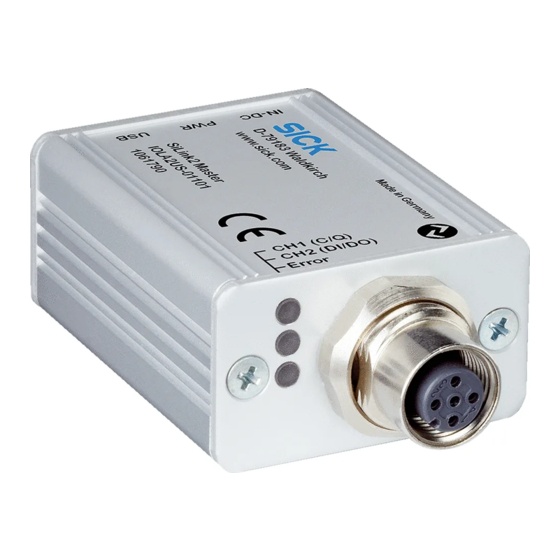
Operating instructions IO-Link USB Master SiLink2 Master Identification Identification Type Label Made in Germany D-79183 Waldkirch www.sick.com SiLink2 Master IOLA2US-01101 1061790 Fig. 1: Type Label IO-Link symbol Labeling Mini USB B interface (side) LED labeling (side) LED labeling (side) CE mark... -
Page 10: Function
Operating instructions IO-Link USB Master SiLink2 Master Structure and Function Function The SiLink2 Master is used as an adapter between an IO-Link device and a PC with a Windows operating system. IO-Link devices can be configured via the SiLink2 Master and a configuration program such as SOPAS ET or an FDT-based configuration program. Status Indicators Function Displays (LEDs) Function Display Description • LED yellow: supply via the USB port. • LED off: no operation CH1 (C/Q) Display IO-Link and SIO mode • LED green – Slow flashing: no IO-Link connection present – Quick flashing: IO-Link connection is in the 'Preoperate' mode – Illuminated: a data exchange (operate) is taking place via the IO-Link connection. • LED yellow: SIO mode CH2 (DI/DO) • LED yellow display SIO mode Error • LED red display of error: short-circuit or data transmission error Table 1: Function displays (LEDs) © SICK AG • Presence Detection • Subject to change without notice • 8017387... -
Page 11: Electrical Connection
NOTE! If the power requirement of the IO-Link device is > 80 mA, connect the supplied wall plug to the DC 24 V female connector of the SiLink Master and connect the wall plug to the supply voltage. © SICK AG • Presence Detection • Subject to change without notice • 8017387... -
Page 12: Connection Diagram
Ground (0 V) Table 2: Description Mini USB B 5.3.2 IO-Link Connection Diagram Fig. 6: IO-Link connection diagram, M12 male connector, 5-pole, A-coding Contact Signal Description +24 V Supply voltage: DC +24 V SIO: CH2 (DI/DO) Supply voltage: 0 V IO-Link IO-Link: CH1 (C/Q) – nc: not assigned Table 3: Description IO-Link, M12 male connector, 5-pole, A-coding © SICK AG • Presence Detection • Subject to change without notice • 8017387... -
Page 13: Installing Software
Operating instructions IO-Link USB Master SiLink2 Master Installing Software Installing Software Required Software In order to be able to configure the IO-Link device via the SiLInk2 Master, you will either need the SOPAS ET configuration program from SICK or a configuration program based on FDT/DTM technology. NOTE! For additional information and for configuration programs, go to 'www.mysick.com/de/silink'. Installation with SOPAS ET Configuration Program You can use the SOPAS ET configuration program from version 2.83 upwards. 1. Start installation of the SOPAS ET configuration program using the 'setup.exe' file. The following window will appear: Fig. 7: SOPAS Engineering Tool Setup © SICK AG • Presence Detection • Subject to change without notice • 8017387... -
Page 14: Installation With Fdt Container
Operating instructions IO-Link USB Master SiLink2 Master Installing Software 2. Install SOPAS ET configuration program according to the installation wizard. 3. Install SDD file of the IO-Link device. 4. Connect SiLink2 Master to the PC and to the IO-Link device. → See Page 11, Chapter 5. 5. Connect IO-Link device according to the Connection Wizard for IO-Link. Fig. 8: IO-Link device in SOPAS ET Installation with FDT Container You can use the gateway DTM from version 2.00 upwards. 1. Start installation of the gateway using the 'setup.exe' file. 2. Install DTM of the IO-Link device or IODD interpreter. In order to do this, start installation using the 'setup.exe' file. 3. Update device catalog via the FDT-based configuration program. In order to do this, click the 'Update' button. Fig. 9: Update device catalog © SICK AG • Presence Detection • Subject to change without notice • 8017387... - Page 15 Operating instructions IO-Link USB Master SiLink2 Master Installing Software NOTE! The SiLink2 Master IOLA2US appears in the device catalog as 'IO-Link USB' of the manufacturer 'IO-Link'. 4. Set up network in the configuration program. 5. Connect SiLink2 Master to the PC and IO-Link device. → See Page 11, Chapter 5. 6. Set up connection in the configuration program. 7. Open user interface of the IO-Link device by double-clicking on the IO-Link device or via the context menu in the configuration program. Fig. 10: Open user interface of the IO-Link device © SICK AG • Presence Detection • Subject to change without notice • 8017387...
-
Page 16: Cleaning And Maintenance
Operating instructions IO-Link USB Master SiLink2 Master Cleaning and Maintenance Cleaning and Maintenance SICK devices are maintenance-free. We do recommend checking the screw and plug connections and cleaning the device at regular intervals. Troubleshooting Indication Possible Cause Troubleshooting Red LED 'Error' illuminated. Data transmission error Transmit data again Short-circuit Change SiLink2 Master. Table 4: Troubleshooting Disposal Observe the following points for disposal: • Do not dispose of the device in domestic refuse. • Dispose of the device according to the relevant country-specific regulations. © SICK AG • Presence Detection • Subject to change without notice • 8017387... -
Page 17: 10 Technical Data
Supply voltage DC 24 V connection of supplied power supply Function display LED (yellow) 'PWR' Mini USB B, connection of PC via supplied USB cable Function display LED (green) 'C1 (C/Q)' Function display LED (yellow) 'C2 (DI/DO)' Function display LED (red) 'Error' M12 male connector, connection IO-Link device © SICK AG • Presence Detection • Subject to change without notice • 8017387... -
Page 18: Supply And Interface
IO-Link port Class A Table 5: Supply 10.3 Ambient Conditions Mark of conformity Protection class Ambient temperature range • Operation: 0 °C … +45 °C • Storage: –40 °C … +80 °C Enclosure rating IP 20 Table 6: Ambient conditions 10.4 Design Configuration Dimensions → See Page 17, Chapter 10.1. Connections • 1 female connector: connection of external wall plug • 1 Mini USB B: PC connection • 1 male connector M12, 5-pole, A-coding: sensor cable connection, 5-pole or 4-pole Table 7: Design Configuration © SICK AG • Presence Detection • Subject to change without notice • 8017387... -
Page 19: Index
EC Declaration of Conformity ........6 Technical data ..............17 Electrical connection Troubleshooting ............16 SiLink2 Master ............11 Electrical specialist Requirement ............. 8 Explanation of symbols ..........5 Connection diagram ..........12 Interface ..............18 FDT/DTM ...............13 Function ................10 Wall plug ...............12 Function displays............10 Incorrect use ..............7 IO-Link Connection diagram ..........12 Interface ..............18 IO-Link mode ..............10 LEDs ................10 Maintenance ..............16 © SICK AG • Presence Detection • Subject to change without notice • 8017387... - Page 20 Phone +972-4-6881000 Phone +90 (216) 528 50 00 e-mail info@sick-sensors.com e-mail info@sick.com.tr Italy United Arab Emirates Phone +39 02 27 43 41 Phone +971 (0) 4 88 65 878 e-mail info@sick.it e-mail info@sick.ae Japan USA/Mexico Phone +81 (0)3 3358 1341 Phone +1(952) 941-6780 e-mail support@sick.jp 1 (800) 325-7425 – toll- Hungary free Phone +36 1 371 2680 e-mail info@sickusa.com e-mail office@sick.hu Netherlands Phone +31 (0)30 229 25 44 More representatives and agencies e-mail info@sick.nl at www.sick.com SICK AG | Waldkirch | Germany | www.sick.com...
Need help?
Do you have a question about the SiLink2 Master IOLA2US-01101 and is the answer not in the manual?
Questions and answers