Table of Contents
Advertisement
CB-200-CTB COIL TUBE BOILER
CB-350-CTB COIL TUBE BOILER
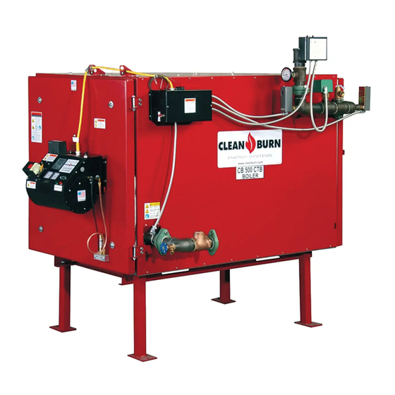
CB-500-CTB COIL TUBE BOILER
U.L. Listed Used Oil
Burning Appliance
#MH15393
PUBLICATION DATE: 1/24/11, Rev. 11
WARNING: DO NOT assemble, install, operate, or maintain this equipment without first
reading and understanding the information provided in this manual. Installation and
service must be accomplished by qualified personnel. Failure to follow all safety precautions
and procedures as stated in this manual may result in property damage, serious personal injury
or death.
IMPORTANT FOR U.S. INSTALLATIONS: All installations must be made in accordance with state and local codes
which may differ from the information provided in this manual. Save these instructions for reference.
IMPORTANT FOR CANADIAN INSTALLATIONS: The installation of this equipment is to be accomplished by
qualified personnel and in accordance with the regulation of authorities having jurisdiction and CSA Standard B 139,
Installation Code for Oil Burning Equipment.
OPERATOR'S MANUAL
CLEAN BURN MODELS:
with CB-525-S2 Burner & Metering Pump
with CB-551-H3 Burner & Metering Pump
with CB-551-H5 Burner & Metering Pump
CLEAN BURN PART #43146
Manufactured & Tested to meet
ASME Section IV
I88460−C
Advertisement
Table of Contents

Related Manuals for CLEAN BURN CB-200-CTB

Summary of Contents for CLEAN BURN CB-200-CTB
- Page 1 OPERATOR'S MANUAL CLEAN BURN MODELS: CB-200-CTB COIL TUBE BOILER with CB-525-S2 Burner & Metering Pump CB-350-CTB COIL TUBE BOILER with CB-551-H3 Burner & Metering Pump CB-500-CTB COIL TUBE BOILER with CB-551-H5 Burner & Metering Pump Manufactured & Tested to meet U.L.
-
Page 3: Assembly
TRADEMARKS The Clean Burn logo is a trademark of Clean Burn, Inc. All other brand or product names mentioned are the registered trademarks or trademarks of their respective owners. -
Page 5: Table Of Contents
TABLE OF CONTENTS SECTION 1: INTRODUCTION ..................1-1 Guide to this Manual ......................1-1 For Your Safety........................ 1-2 Guidelines for CTB Usage ..................1-4 Guidelines for Used Oil Tanks .................. 1-5 Safety Labels ......................1-6 SECTION 2: UNPACKING & PRE-INSTALLATION CONSIDERATIONS ....2-1 Removing the Shipping Crate .................. - Page 6 SECTION 7: RESETTING THE OIL PRIMARY CONTROL ........7-1 Understanding the Oil Primary Control ................7-1 Resetting the Oil Primary Control (CB-200-CTB) .............. 7-1 Resetting the Oil Primary Control (CB-350-CTB and CB-500-CTB) ......... 7-2 Primary Control Operation/Troubleshooting Guide (CB-350-CTB and CB-500-CTB) ..7-4 SECTION 8: ADJUSTING THE DRAFT OVER FIRE ..........
- Page 7 CTB Accessories and Parts Reference ................ A-3 CTB Dimensions ......................A-4 Single Boiler Assembly Component Detail ..............A-10 Burner Components ....................A-12 CB-525-S2 (CB-200-CTB) ................A-12 CB-551-H3 (CB-350-CTB) ................A-14 CB-551-H5 (CB-500-CTB) ................A-18 Removing the Nozzle for cleaning ................ A-23 CB-200-CTB Components ..................
- Page 8 TABLE OF CONTENTS APPENDIX B Wiring Diagrams ....................... B-1 CTB Sequence of Operation ..................B-4 CTB Ladder Schematic ....................B-5 Metering Pump Wiring Schematic ................B-6 APPENDIX C CTB Service Record ......................C-1...
-
Page 9: Section 1: Introduction
SECTION 1: INTRODUCTION Guide to this Manual This manual contains all the information necessary to safely install and operate the Clean Burn Coil Tube Boilers (CTB), Model CB-200-CTB, CB-350-CTB, and CB-500-CTB. Consult the Table of Contents for a detailed list of topics covered. You'll find this manual's step-by-step procedures easy to follow and understand. - Page 10 Coil Tube Boiler Operator's Manual: Models CB-200-CTB, CB-350-CTB, and CB-500-CTB For Your Safety... For your safety, Clean Burn documentation contains the following types of safety statements (listed here in order of increasing intensity): • NOTE: A clarification of previous information or additional pertinent information.
- Page 11 Clean Burn, Inc. Unauthorized modifications or alteration can adversely affect the proper, safe operation of your boiler. WARNING: The burner which is shipped with your Clean Burn CTB is to be used only with your boiler according to the instructions provided in this manual. DO NOT use the...
- Page 12 Contact your Clean Burn dealer for current EPA regulations. • If your CTB ever requires service, call your Clean Burn dealer. DO NOT allow untrained, unauthorized personnel to service your CTB. Make sure that your boiler receives annual preventative maintenance to ensure optimal performance.
- Page 13 Coil Tube Boiler Operator's Manual: Models CB-200-CTB, CB-350-CTB, and CB-500-CTB For Your Safety... (continued) Guidelines for Used Oil Tanks For the safe storage of used oil and the safety of persons in the vicinity of the used oil supply tank,...
- Page 14 CTB, review all labels and heed all safety messages as printed on the labels. If any labels on your Clean Burn CTB ever become worn, lost or painted over, please call your Clean Burn dealer for free replacements.
- Page 15 Coil Tube Boiler Operator's Manual: Models CB-200-CTB, CB-350-CTB, and CB-500-CTB CTB Cabinet Labels (continued) 42216 42497 42465 42286 www.cleanburn.com 42216 42493 CB *** CTB 42286 42421 Burn Hazard. Fittings, piping, and boiler surface may be extremely hot. Pipes contain hot water.
- Page 16 Coil Tube Boiler Operator's Manual: Models CB-200-CTB, CB-350-CTB, and CB-500-CTB For Your Safety... (continued) CTB Cabinet Safety Labels (continued) LANCASTER, PENNSYLVANIA (USA) MH15393 USED OIL−FIRED FURNACE USED−OIL BURNING APPLIANCE USED OIL−FIRED BOILER For use with Integral Primary Safety Control 13084 MULTI−OIL HEATING SYSTEM...
- Page 17 Coil Tube Boiler Operator's Manual: Models CB-200-CTB, CB-350-CTB, and CB-500-CTB For Your Safety... (continued) CTB Cabinet Safety Labels (continued) CB 500 CTB INPUT RATING W/NO 2 FUEL OIL (BTU/HR) 500000 3.57 3.57 3.57 3.57 3.57 3.57 −.06 SIDE POWER 1/20 1/10 21.0...
- Page 18 Coil Tube Boiler Operator's Manual: Models CB-200-CTB, CB-350-CTB, and CB-500-CTB For Your Safety... (continued) CTB BurnerSafety Labels (continued) CTB Burner Labels 200-CTB 350-CTB 500-CTB Description 42005 42005 42005 Sold/Serviced By Label 42004 42004 42004 Burner Safety Warning Label (High Voltage/Moving Parts Hazard)
-
Page 19: For Your Safety
Coil Tube Boiler Operator's Manual: Models CB-200-CTB, CB-350-CTB, and CB-500-CTB For Your Safety... (continued) Metering Pump Labels 200-CTB 350-CTB 500-CTB Description 42284 42284 42284 Metering Pump Wiring Diagram 42466 42420 42495 Model Number / Warning 1-11... - Page 20 Coil Tube Boiler Operator's Manual: Models CB-200-CTB, CB-350-CTB, and CB-500-CTB 1-12...
-
Page 21: Section 2: Unpacking & Pre-Installation Considerations
ATTENTION: DO NOT attempt to slide the CTB out of the shipping crate - you may damage the cabinet. Unpacking and Inspection Following is an itemized list of all components you should have received in your Clean Burn Coil Tube Boiler shipment. Open all shipping containers and inspect all components according to the list. -
Page 22: Warranty Registration
1835 Freedom Road Lancaster, Pennsylvania 17601 Pre-Installation Considerations The following information is critical to the proper installation of your Clean Burn Coil Tube Boiler system; read this section carefully before starting any other procedures. Determining the CTB System Setup Before installing the CTB, you must determine the following which relate to your installation:... - Page 23 Coil Tube Boiler Operator's Manual: Models CB-200-CTB, CB-350-CTB, and CB-500-CTB Selecting a Location (continued) Adhere to the following minimum clearances from combustible surfaces. Specifications are also provided for servicing clearance. Be sure to check state and local codes which may differ from these specifications.
- Page 24 Coil Tube Boiler Operator's Manual: Models CB-200-CTB, CB-350-CTB, and CB-500-CTB...
-
Page 25: Section 3: Coil Tube Boiler Assembly
SECTION 3: COIL TUBE BOILER ASSEMBLY Understanding Assembly Assembling your Clean Burn Coil Tube Boiler (CTB) is a multi-step process. Note that some assembly procedures apply only to certain CTB installations or configurations (i.e. single model or dual-stacked boilers); the assembly procedures are outlined below as they appear in this section. -
Page 26: Single Boiler Assembly Component Detail
Coil Tube Boiler Operator's Manual: Models CB-200-CTB, CB-350-CTB, and CB-500-CTB Single Boiler Assembly DETAIL OF ITEM 24 CB−350−CTB SHOWN (USER SUPPLIED) I88121−F Figure 3A - Single Boiler Assembly Component Detail... - Page 27 Coil Tube Boiler Operator's Manual: Models CB-200-CTB, CB-350-CTB, and CB-500-CTB CB-350-CTB PARTS LIST NUMBER PART # DESCRIPTION 90188 BASE 33331 TERMINAL BLOCK 33327 TRANSFORMER 120V-24V 33328 RELAY DPDT 33352 RELAY DELAY 33486 TERMINAL BLOCK ASSEMBLY 33286 SWITCH DPDT 33168 AMBER LIGHT...
-
Page 28: Installing The Ctb On The Support Stand
WARNING: Use extreme caution when moving and lifting the CTB (with a forklift) into place on the support stand. One CTB can weigh up to 2000 pounds (approximate). Clean Burn recommends placing safety blocking underneath the unit until it is properly installed and secured on the support stand. -
Page 29: Dual-Stacked Boiler Assembly
WARNING: Use extreme caution when moving and lifting one of the CTB's (with a forklift) into place on the support stand. One CTB can weigh up to 2000 pounds (approximate). Clean Burn recommends placing safety blocking underneath the unit until it is properly installed and secured on the support stand. - Page 30 Coil Tube Boiler Operator's Manual: Models CB-200-CTB, CB-350-CTB, and CB-500-CTB Dual-Stacked Boiler Assembly "TOP" BOILER (USER SUPPLIED) ADAPTOR BRACKET "BOTTOM" BOILER (USER SUPPLIED) SUPPORT STAND I88671-B Figure 3D - Dual-Stacked Boiler Assembly Detail...
- Page 31 "bottom" boiler while checking for proper alignment of the two units. Ensure that ALL hardware is securely tightened. NOTE: When stacking a CB-200-CTB on top of a CB-350-CTB use an additional set of side channels turned 180 degrees to help distribute the load around the fork lift notches. This will require lifting the "top"...
-
Page 32: Assembly For All Boilers
Coil Tube Boiler Operator's Manual: Models CB-200-CTB, CB-350-CTB, and CB-500-CTB Assembly for ALL Boilers Connecting the CTB Refer to Figures 3A, 3C, and 3D. Connecting the boiler involves three activities: • Supply Side Connections • Return Side Connections • Wiring NOTE: If you are installing dual-stacked boilers, each boiler must be installed in the same manner according to the following guidelines for connections/wiring. -
Page 33: Installing The Ceramic Sleeve
Coil Tube Boiler Operator's Manual: Models CB-200-CTB, CB-350-CTB, and CB-500-CTB Assembly for ALL Boilers Installing the Ceramic Sleeve in the Boiler NOTE: The ceramic target is factory-installed. Refer to Figures 3F and 3G. Swing open the clean-out door on the CTB front to gain access to the combustion chamber. - Page 34 Coil Tube Boiler Operator's Manual: Models CB-200-CTB, CB-350-CTB, and CB-500-CTB Assembly for ALL Boilers CERAMIC SLEEVE CERAMIC I88124-B STAND Figure 3G - Ceramic Stand and Sleeve Installed in the Combustion Chamber 3-10...
-
Page 35: Checking The Burner Nozzle And Electrodes
Assembly for ALL Boilers Checking the Burner Nozzle and Electrodes NOTE: The burner nozzle is factory installed. Models CB-200-CTB and CB-350-CTB use a Delavan 9-5 nozzle. Model CB-500-CTB uses a 9-28 Delavan nozzle. The nozzle size is indicated on the nozzles as shown in Figure 3H. -
Page 36: Mounting The Burner
Coil Tube Boiler Operator's Manual: Models CB-200-CTB, CB-350-CTB, and CB-500-CTB Assembly for ALL Boilers Mounting the Burner on the Hinge Bracket NOTE: The burner may have been mounted on the CTB at the factory. If this is the case, simply check the clearance between the retention head and the boiler to make sure the burner swings freely into firing position. -
Page 37: Installing The Oil Line Tubing
Coil Tube Boiler Operator's Manual: Models CB-200-CTB, CB-350-CTB, and CB-500-CTB Assembly for ALL Boilers Installing the Oil Line Tubing OIL LINE NOTE: DO NOT disassemble the compression OIL FITTING ON BURNER fitting from the swivel fitting. To prevent leaks, the... -
Page 38: Installing The Air Line Tubing
Coil Tube Boiler Operator's Manual: Models CB-200-CTB, CB-350-CTB, and CB-500-CTB Assembly for ALL Boilers AIR LINE FITTING ON BURNER OIL LINE FITTING ON BURNER AIR LINE OIL LINE COMPRESSION / SWIVEL FITTING CONNECTOR BLOCK INSTALLED ON BOILER I88112−B Figure 3J - Installation of Connector Block, Oil Line and Air Line (Front View) Installing the Air Line Tubing Remove and discard the outer red protective caps from the air line tubing. -
Page 39: Section 4: Coil Tube Boiler Installation
Likewise, the installation, operation, and maintenance of this equipment in Canada is to be accomplished by qualified personnel and in compliance with the specifications in the Clean Burn Operator's Manual and in accordance with the regulation of authorities having jurisdiction and the following CSA Standards:... -
Page 40: Typical Installation Diagrams
Coil Tube Boiler Operator's Manual: Models CB-200-CTB, CB-350-CTB, and CB-500-CTB Typical Installation Diagrams "CLASS A" STACK CAP 10 FT "CLASS A" STACK 2100 DEGREE ALL FUEL STACK INSULATED STACK WITH A STAINLESS STEEL LINER WATERTIGHT ROOF FLASHING "DEKTITE" FLASHING OR EQUIVALENT "CLASS A"... - Page 41 Coil Tube Boiler Operator's Manual: Models CB-200-CTB, CB-350-CTB, and CB-500-CTB Typical Installation Diagrams (continued) "CLASS A" STACK CAP "CLASS A" STACK 2100 DEGREE ALL FUEL STACK 10 FT INSULATED STACK WITH A STAINLESS STEEL LINER WATERTIGHT ROOF FLASHING "DEKTITE" FLASHING OR EQUIVALENT "CLASS A"...
-
Page 42: Combustion Air Requirements
Coil Tube Boiler Operator's Manual: Models CB-200-CTB, CB-350-CTB, and CB-500-CTB Combustion Air Requirements The CTB system designer/installer must ensure that there is the proper amount of combustion air in the boiler/ mechanical room. Refer to Figure 4C. Combustion Air is the required amount of air that the equipment needs to permit the satisfactory combustion of oil, the proper venting of combustion gases, and to maintain a safe ambient temperature within the space at safe limits under normal conditions of use. - Page 43 Coil Tube Boiler Operator's Manual: Models CB-200-CTB, CB-350-CTB, and CB-500-CTB...
-
Page 44: Oil Tank Installation Specifications
Coil Tube Boiler Operator's Manual: Models CB-200-CTB, CB-350-CTB, and CB-500-CTB Oil Tank Installation Specifications Ensure that your tank installation adheres to the following safety guidelines as stated here and in Section 1 of this manual. The tank safety label (shown at right) also summarizes these important specifications for tank installation and usage. -
Page 45: Installing The Tank Vent And Emergency Vent
Some codes require that you install a tank vent (to the outside) and an emergency vent for your tank as shown in Figure 4D. Tank Vent Kits are available from Clean Burn; contact your local Clean Burn dealer to order. -
Page 46: Installing The Metering Pump
Coil Tube Boiler Operator's Manual: Models CB-200-CTB, CB-350-CTB, and CB-500-CTB Installing the Metering Pump Preparing for Installation Before starting installation of the metering pump, review Figures 4E, 4F, and 4G to become familiar with the metering pump components. You will also need to accomplish the following activities: •... - Page 47 Coil Tube Boiler Operator's Manual: Models CB-200-CTB, CB-350-CTB, and CB-500-CTB PART # DESCRIPTION 33363 CAPACITOR − GEARMOTOR see chart GEARMOTOR 11322 MOUNT − METER PUMP 32037 1/8 NPT X 1/4 TUBE COMPRESSION FITTING 1/4 COPPER OR ALUM. TUBING 3/8 OR 1/2 TUBE FLARE NUT 3/8 OR 1/2 COPPER OR ALUM.
-
Page 48: Alternate Mounting: Horizontal Positioning
Coil Tube Boiler Operator's Manual: Models CB-200-CTB, CB-350-CTB, and CB-500-CTB Alternate Mounting: Horizontal Positioning ATTENTION: If the metering pump is to be mounted horizontally or on a bracket as shown in Figure 4G, the pump head must be rotated counterclockwise so that it is aligned in a horizontal position. The gauge arrow on the pump head must point up, or the pump will not prime. -
Page 49: Connecting Water To The Coil Tube Boiler
For air separation and elimination, Clean Burn recommends the Enhanced Spiral-Type Air Separator which can be supplied by your local Clean Burn dealer. Installing an air separator helps ensure that air is purged from the boiler, which is necessary for optimal startup and operation of the burner. -
Page 50: Installing The Suction Oil Line Components
Coil Tube Boiler Operator's Manual: Models CB-200-CTB, CB-350-CTB, and CB-500-CTB Installing the Suction Oil Line Components ATTENTION: It is critical that you adhere to the following specifications for suction oil line installation (oil line from the tank to the pump). If these specifications are not met, the metering pump will not function correctly and the burner will shut down on reset. - Page 51 Coil Tube Boiler Operator's Manual: Models CB-200-CTB, CB-350-CTB, and CB-500-CTB Installing the Suction Oil Line Components (continued) (e.) Prepare the canister filter for installation (continued): • Remove the plug from one of the 1/8" gauge ports in the canister filter and install the vacuum gauge.
- Page 52 Coil Tube Boiler Operator's Manual: Models CB-200-CTB, CB-350-CTB, and CB-500-CTB Installing the Suction Oil Line Components (continued) (2.) Install the suction oil line (continued)): m. Slide the 1/2" flare nut over the end of the 1/2" copper tubing, and flare the end of the tubing.
-
Page 53: Installing The Pressure Relief Oil Line Back To The Tank
Coil Tube Boiler Operator's Manual: Models CB-200-CTB, CB-350-CTB, and CB-500-CTB Installing the Pressure Relief Oil Line Back to the Tank ATTENTION: It is critical that you adhere to the following specifications for plumbing the pressure relief back to the tank. -
Page 54: Installing The Pressure Oil Line Components
Coil Tube Boiler Operator's Manual: Models CB-200-CTB, CB-350-CTB, and CB-500-CTB Installing the Pressure Oil Line Components ATTENTION: It is critical that you adhere to the following specifications for pressure oil line installation (oil line from the pump to the boiler); if these specifications are not met, the metering pump will not function correctly and the burner will shut down on reset. -
Page 55: Wiring The Coil Tube Boiler
Properly size all wires and use Greenfield or Thin-wall Conduit for all electrical lines. Refer to Figures 4A/4B at the beginning of this chapter for the Clean Burn recommended typical CTB installation. Specific wiring schematics are provided in Appendix B at the back of this manual. -
Page 56: Wiring To The Oil Pump
NOTE: To reduce the amount of cold water returned to the boiler (and to protect the boiler from thermal shock), an optional circulator aquastat can be supplied by your Clean Burn Dealer. Refer to the related information and illustrations in Section 10 and the CTB Wiring Diagram in Appendix B to locate and understand the wiring for the load loop circulator. -
Page 57: Installing The Stack
• Model CB-500-CTB single boilers require 10" I.D. stack components. • Models CB-200-CTB and CB-350-CTB dual-stacked units require 8" I.D. stack components run as two (2) individual stacks. • Model CB-500-CTB dual-stacked units require 10" I.D. stack components run as two (2) individual stacks. -
Page 58: Installing The Interior Stack
Coil Tube Boiler Operator's Manual: Models CB-200-CTB, CB-350-CTB, and CB-500-CTB "CLASS A" STACK CAP NON−RESTRICTIVE TYPE TO ALLOW FREE FLOW OF TH STACK GASES THE LAST STACK SECTION SHALL EXTEND AT LEAST 3 FEET ABOVE "CLASS A" UL 103HT STACK THE HIGHEST POINT. -
Page 59: Installing The Barometric Damper
Coil Tube Boiler Operator's Manual: Models CB-200-CTB, CB-350-CTB, and CB-500-CTB Installing the Stack (continued) DAMPER 8" 32 1/4" BETWEEN CENTERS (CB−200−CTB) 37 1/8" BETWEEN CENTERS (CB−350−CTB) 8" 10" BETWEEN OPENING CENTERS I88672-A Figure 4J - Detail of Dual-Stacked Boiler Stack Installation Install an elbow or clean-out tee (with a smoke cap installed in the bottom) onto the extension piece from the boiler smoke hood breach. - Page 60 Coil Tube Boiler Operator's Manual: Models CB-200-CTB, CB-350-CTB, and CB-500-CTB Installing the Stack (continued) For CB-500-CTB ONLY: Install the 9"-to-10" pipe adapter in the opening of the tee as shown in Figure 4K. Install the barometric damper in the opening of the tee (or pipe adapter for CB-500-CTB). Use a small spirit level to make sure that it is properly level.
-
Page 61: Installing The Stack Safety Switch For Canadian Installations
Coil Tube Boiler Operator's Manual: Models CB-200-CTB, CB-350-CTB, and CB-500-CTB Installing the Stack Safety Switch For Canadian Installations NOTE: CSA Standards require that all heating equipment must be installed with a stack safety switch. If your heating equipment is being installed in Canada, follow the instructions listed below. -
Page 62: Resetting The Stack Safety Switch
Coil Tube Boiler Operator's Manual: Models CB-200-CTB, CB-350-CTB, and CB-500-CTB Resetting the Stack Safety Switch WARNING: BURN HAZARD! To prevent serious personal injury, be sure to allow ample time, at least 30 minutes, for the stack, barometric damper, and switch to cool down before attempting to access and service these components. -
Page 63: Installing The Stack Penetration
Install the stack cap according to the manufacturer's instructions. Installing the Draft Inducer ATTENTION: The Field brand draft inducers have been tested for use on Clean Burn Equipment. DO NOT use other models or brands of draft inducers. Understanding the Importance of the Draft Inducer The draft inducer is designed to aid in the removal of the natural draft created by the appliance to vent the combustion gases to the outside of the building. - Page 64 Coil Tube Boiler Operator's Manual: Models CB-200-CTB, CB-350-CTB, and CB-500-CTB Installing the Draft Inducer (continued) NOTE: Lubricate the motor as recommended by the Draft Inducer manufacturer. 3 FEET 10 FEET 10 FT MINIMUM VERTICAL STACK HEIGHT OR EQUIVALENT DRAFT SYSTEM TO MAINTAIN −.02 W.C.
-
Page 65: Installing The Wall Thermostat
Installing the Wall Thermostat or Aquastat IMPORTANT NOTE: The wall thermostat is available separately from Clean Burn (i.e. it is not included with the CTB). Refer to Appendix A in this manual for additional information on remote temperature sensing con- trols available from Clean Burn for your CTB system installation. - Page 66 Coil Tube Boiler Operator's Manual: Models CB-200-CTB, CB-350-CTB, and CB-500-CTB Inspecting the Coil Tube Boiler Installation Following the completion of all installation activities described in this chapter, the CTB should be inspected by qualified personnel before firing. This ensures that your installation meets all applicable national and local codes and allows for any deficiencies in the installation to be corrected before CTB startup.
-
Page 67: Section 5: Metering Pump Priming
SECTION 5: METERING PUMP PRIMING Understanding Metering Pump Priming Preparing your Clean Burn boiler for operation begins with priming the metering pump. The procedures in this section must be performed in sequence without interruption to properly prime the pump. IMPORTANT NOTE FOR DUAL-STACKED UNITS: The priming procedures will have to be per- formed for one burner, and then repeated for the other burner (i.e. -
Page 68: Priming The Metering Pump
Coil Tube Boiler Operator's Manual: Models CB-200-CTB, CB-350-CTB, and CB-500-CTB Priming the Metering Pump ATTENTION: The priming process must be done precisely as described in this procedure to ensure that all air is thoroughly bled from the system. Failure to bleed all air from the system will result in repeated burner shutdowns on reset. - Page 69 Coil Tube Boiler Operator's Manual: Models CB-200-CTB, CB-350-CTB, and CB-500-CTB Priming the Metering Pump (continued) Activating the Pump NOTE: The coil tube boiler features a priming switch which is mounted on the left-hand side of the electrical junction box on the hydraunics side of the boiler cabinet. The priming switch has two positions: •...
-
Page 70: Vacuum Testing The Oil Pump
Coil Tube Boiler Operator's Manual: Models CB-200-CTB, CB-350-CTB, and CB-500-CTB Priming the Metering Pump (continued) Run the pump until a solid stream of oil flows from the pump bleeder. This will bleed all air out of the suction line, oil filter and pump head. - Page 71 Coil Tube Boiler Operator's Manual: Models CB-200-CTB, CB-350-CTB, and CB-500-CTB Vacuum Testing the Oil Pump (continued) If there are no suction leaks, the system will hold vacuum. NOTE: It is acceptable for the vacuum to drop one to five inches within one minute as the seal in the pump seats.
- Page 72 Coil Tube Boiler Operator's Manual: Models CB-200-CTB, CB-350-CTB, and CB-500-CTB...
-
Page 73: Section 6: Starting And Adjusting The Burner
Section 10 in this manual for more information on the hydronics system. DO NOT bypass the CTB controls to operate the burner! FOR DUAL-STACKED UNITS ONLY: Clean Burn recommends that you complete burner startup and adjustment for one burner before starting the second burner. - Page 74 NOTE: The oil pressure is automatically adjusted by the metering pump. Initial Adjustments for CB-200-CTB NOTE: Only Gearmotor part #33507 may be used with the CB-200-CTB. Maximum Input = 200,000 BTUH @ 1.4 GPH per CB 525-S2 Burner Oil Type...
-
Page 75: Starting The Burner
Coil Tube Boiler Operator's Manual: Models CB-200-CTB, CB-350-CTB, and CB-500-CTB Preparing the Burner for Startup (continued) Initial Adjustments for CB-350-CTB NOTE: Only Gearmotor part #33295 may be used with the CB-350-CTB. Maximum Input = 350,000 BTUH @ 2.5 GPH per CB 551-H3 Burner... - Page 76 Coil Tube Boiler Operator's Manual: Models CB-200-CTB, CB-350-CTB, and CB-500-CTB Starting the Burner (continued) Correct Maximum Flame Adjustment (Proper Oil and Air Pressure) • Flame goes half of the way down the combustion chamber. • Flame does not touch back of walls of combustion chamber.
- Page 77 • Cad cell reading of 200 to 500 ohms NOTE: On the CB-200-CTB, the flame cannot be observed through the inspection door. The CB-200-CTB must be adjusted with instruments for proper combustion. Obtain the above settings by adjusting the air band 3/8" to 1/2". The metering pump will deliver a constant oil flow and...
- Page 78 Coil Tube Boiler Operator's Manual: Models CB-200-CTB, CB-350-CTB, and CB-500-CTB...
-
Page 79: Section 7: Resetting The Oil Primary Control
Coil Tube Boiler Operator's Manual: Models CB-200-CTB, CB-350-CTB, and CB-500-CTB SECTION 7: RESETTING THE OIL PRIMARY CONTROL Understanding the Oil Primary Control (CB-200-CTB) The oil primary control will go into safety lockout and shut the burner off when it detects flame-out during burner operation. - Page 80 Coil Tube Boiler Operator's Manual: Models CB-200-CTB, CB-350-CTB, and CB-500-CTB Understanding the Oil Primary Control (CB-350-CTB and CB-500-CTB) NOTE: This is a new control featuring the ability to activate a remote alarm in case of lock-out or latch-up. The oil primary control will go into safety lock-out and shut the burner off when it detects flame-out during burner operation.
- Page 81 Coil Tube Boiler Operator's Manual: Models CB-200-CTB, CB-350-CTB, and CB-500-CTB Resetting the Oil Primary Control (continued) Set the load temperature controller to call for heat. NOTE: Main power should be ON and all hand-operated oil line valves open. When the call for heat is detected, the oil primary control will perform a 3-4 second self-test which is indicated by a "solid on"...
- Page 82 Coil Tube Boiler Operator's Manual: Models CB-200-CTB, CB-350-CTB, and CB-500-CTB...
-
Page 83: Section 8: Adjusting The Draft Over Fire
Checking for Correct Draft Over Fire NOTE: The CTB's are equipped with an observation/draft reading port to check draft over fire. A qualified serviceman with proper equipment must adjust your CTB for proper draft. Contact your Clean Burn dealer for this service. -
Page 84: Understanding The Effect Of Exhaust Fans On Draft
Coil Tube Boiler Operator's Manual: Models CB-200-CTB, CB-350-CTB, and CB-500-CTB Checking for Correct Draft Over Fire (continued) Backdraft is caused by the following conditions: • Poor draft caused by improper stack design. (See Section 4.) • Poor draft caused by improper adjustment of the barometric damper. -
Page 85: Adjusting Draft Over Fire With A Draft Inducer Installed
Coil Tube Boiler Operator's Manual: Models CB-200-CTB, CB-350-CTB, and CB-500-CTB Adjusting Draft Over Fire with A Draft Inducer Installed NOTE: The draft inducer is purposely sized to create a generous draft. When adjusting the barometric damper, you will find that the flapper is open most of the time. This allows the draft inducer to suck cool air through the damper to protect the inducer motor from heat damage. - Page 86 Coil Tube Boiler Operator's Manual: Models CB-200-CTB, CB-350-CTB, and CB-500-CTB...
-
Page 87: Section 9: Maintenance
Clean Burn service technician who has the necessary parts and expertise. Contact your local Clean Burn dealer to schedule the annual maintenance for your boiler. Various levels of service are provided to fit your particular need. This work is usually performed during the... -
Page 88: Cleaning The Canister Filter
Coil Tube Boiler Operator's Manual: Models CB-200-CTB, CB-350-CTB, and CB-500-CTB Cleaning the Canister Filter ATTENTION: Never operate the oil pump with more than 10" HG of vacuum on the vacuum gauge. High vacuum on the suction side of the pump separates air from the oil (cavitation) and will cause the burner to shut down. -
Page 89: Servicing The Metering Pump
Coil Tube Boiler Operator's Manual: Models CB-200-CTB, CB-350-CTB, and CB-500-CTB Servicing the Metering Pump Refer to Figure 9B. Remove the pump head cover (part 1). Remove the screen (part 2) and wash it. Remove and discard the used gasket (part 3). - Page 90 Coil Tube Boiler Operator's Manual: Models CB-200-CTB, CB-350-CTB, and CB-500-CTB TO BURNER METERING PUMP FUNNEL WITH BALL VALVE VENT SUCTION OIL LINE EMERGENCY VENT OIL STORAGE TANK CLEANOUT CHECK VALVE CHECK VALVE SCREEN 12" I88670−F Figure 9C - Check Valve Detail...
- Page 91 Coil Tube Boiler Operator's Manual: Models CB-200-CTB, CB-350-CTB, and CB-500-CTB Clean the ash from the combustion chamber (see Figure 9D): a. If the air and oil lines must be disconnected to open the clean out door: 1. Bleed-down pressure on the air and oil lines by slightly loosening the fittings at the bottom of the connector block.
-
Page 92: Cleaning The Oil Tank
"heat recovery." DO NOT operate your boiler during warm weather just to burn oil. Contact your local Clean Burn dealer to schedule your annual burner tune-up. Allow only trained, authorized service personnel to service your burner. -
Page 93: Section 10: The Ctb Hydronic System
Understanding the CTB Hydronic System The Clean Burn Coil Tube Boiler (CTB) is designed to function as a low-mass boiler (i.e. it will not maintain boiler water temperature when there is no call for heat). Low-mass boilers require that a sufficient, constant flow of water be maintained through the coil in order to: (a) remove the heat from the boiler when the burner is firing AND (b) prevent the flow switch from shutting off the burner. -
Page 94: Ctb System Function And Configuration
Clean Burn Service Department for proper pressure requirements. Sample System Configuration: Primary/Secondary Pumping System A sample hydronic system setup using Clean Burn Coil Tube Boilers is shown in Figure 10A. This system, a Primary/Secondary Pumping System, allows for many special hydronic requirements (e.g. water return... - Page 95 Coil Tube Boiler Operator's Manual: Models CB-200-CTB, CB-350-CTB, and CB-500-CTB 10-3...
-
Page 96: Ctb Setup Options
(2) In low load conditions, Clean Burn recommends the installation of a larger storage tank next to the CTB to extend the run time and to reduce the occurrence of short cycling. Position the tank close to the boiler to reduce the required connective piping as shown in sample configuration, Figure 10B. - Page 97 Coil Tube Boiler Operator's Manual: Models CB-200-CTB, CB-350-CTB, and CB-500-CTB 10-5...
- Page 98 Coil Tube Boiler Operator's Manual: Models CB-200-CTB, CB-350-CTB, and CB-500-CTB 10-6...
-
Page 99: Guidelines For Ctb Setup And Operation
Coil Tube Boiler Operator's Manual: Models CB-200-CTB, CB-350-CTB, and CB-500-CTB Guidelines for CTB Setup and Operation Refer to the appropriate illustration in this section for your CTB system configuration, as well as Figures 4A/4B in the Installation chapter. Connect the supply and return piping to the heating system. (Additional information in Section 4). -
Page 100: Guidelines For Preventing Oxygen Contamination
Coil Tube Boiler Operator's Manual: Models CB-200-CTB, CB-350-CTB, and CB-500-CTB Guidelines for Preventing Oxygen Contamination ATTENTION: Oxygen contamination of boiler water will cause corrosion of iron and steel boiler components, and can lead to boiler failure (and void warranty). Causes of oxygen contamination include: •... -
Page 101: Section 11: Troubleshooting
Coil Tube Boiler Operator's Manual: Models CB-200-CTB, CB-350-CTB, and CB-500-CTB SECTION 11: TROUBLESHOOTING The following charts and tables are provided for reference in troubleshooting any difficulties encountered in boiler operation and adjustment. • The Flow Chart outlines the proper sequence of events in boiler operation -- use this chart to help diagnose where a problem may be occurring. - Page 102 Coil Tube Boiler Operator's Manual: Models CB-200-CTB, CB-350-CTB, and CB-500-CTB 11-2...
- Page 103 Coil Tube Boiler Operator's Manual: Models CB-200-CTB, CB-350-CTB, and CB-500-CTB PROBLEM POSSIBLE CAUSE POSSIBLE ACTION(S) Burner won’t run at all and Circuit breaker/main switch open. Close circuit breaker/switch. Green power light is NOT ON. Fuse/breaker blown. Electrician should check out electrical system.
- Page 104 Coil Tube Boiler Operator's Manual: Models CB-200-CTB, CB-350-CTB, and CB-500-CTB PROBLEM POSSIBLE CAUSE POSSIBLE ACTION(S) Burner ignites, but will not stay running There is a fuel delivery problem. Follow the procedures listed in the and Burner shuts off on reset within 15 next problem.
- Page 105 Coil Tube Boiler Operator's Manual: Models CB-200-CTB, CB-350-CTB, and CB-500-CTB PROBLEM POSSIBLE CAUSE POSSIBLE ACTION(S) Burner ignites and Burner shuts off on There is air in the fuel supply. Prime the pump. If the pump will reset sometime later during the day or not prime or there is air in the oil night.
- Page 106 Coil Tube Boiler Operator's Manual: Models CB-200-CTB, CB-350-CTB, and CB-500-CTB PROBLEM POSSIBLE CAUSE POSSIBLE ACTION(S) Pump will not prime and Pump motor is There is a leak(s) in the suction Follow the specifications in running. line. Section 4 to make sure the...
- Page 107 Coil Tube Boiler Operator's Manual: Models CB-200-CTB, CB-350-CTB, and CB-500-CTB PROBLEM POSSIBLE CAUSE POSSIBLE ACTION(S) Pump will not prime and Pump motor is There is NO power on the Start the burner and adjust the air NOT running. pump circuit from the burner.
- Page 108 Coil Tube Boiler Operator's Manual: Models CB-200-CTB, CB-350-CTB, and CB-500-CTB 11-8...
-
Page 109: Ctb Technical Specifications
Coil Tube Boiler Operator's Manual: Models CB-200-CTB, CB-350-CTB, and CB-500-CTB APPENDIX A Detailed Coil Tube Boiler Specifications CTB Technical Specifications Model CB-200-CTB CB-350-CTB CB-500-CTB BTUH Input 200,000* 350,000* 500,000* Listed Fuels: #2 Fuel Oil 3.57 Used Crankcase Oil Used ATF... -
Page 110: Burner Technical Specifications
Coil Tube Boiler Operator's Manual: Models CB-200-CTB, CB-350-CTB, and CB-500-CTB Burner Technical Specifications Model CB-200-CTB CB-350-CTB CB-500-CTB Burner CB-525-S2 CB-551-H3 CB-551-H5 Ignition Transformer Carlin Carlin Carlin 14,000 Volts 14,000 Volts 14,000 Volts Nozzle Delavan 9-5 Delavan 9-5 Delavan 9-28 Burner Motor... -
Page 111: Ctb Accessories And Parts Reference
Coil Tube Boiler Operator's Manual: Models CB-200-CTB, CB-350-CTB, and CB-500-CTB CTB Accessories and Parts Reference C.B. Part # Description 500-CTB 350-CTB 200-CTB 11578 90187 90199 Boiler Stacking Adapter Kit 90206 90188 90200 Boiler Stand (base) 11095 Circulator, TACO 0011, 115VAC 35078 Circulator, B&G PL-36, 115VAC... -
Page 112: Ctb Dimensions
Coil Tube Boiler Operator's Manual: Models CB-200-CTB, CB-350-CTB, and CB-500-CTB CTB Dimensions Figure A1 - Model CB-200-CTB Dimensions (Single Boiler) - Page 113 Coil Tube Boiler Operator's Manual: Models CB-200-CTB, CB-350-CTB, and CB-500-CTB CTB Dimensions Figure A2 - Model CB-350-CTB Dimensions (Single Boiler)
- Page 114 Coil Tube Boiler Operator's Manual: Models CB-200-CTB, CB-350-CTB, and CB-500-CTB CTB Dimensions Figure A4 - Dual-Stacked Boiler Dimensions (Two CB-350-CTB Boilers)
- Page 115 Coil Tube Boiler Operator's Manual: Models CB-200-CTB, CB-350-CTB, and CB-500-CTB CTB Dimensions Figure A3 - Model CB-500-CTB Dimensions...
- Page 116 Coil Tube Boiler Operator's Manual: Models CB-200-CTB, CB-350-CTB, and CB-500-CTB CTB Dimensions Figure A4 - Dual-Stacked Boiler Dimensions (Two CB-500-CTB Boilers)
- Page 117 Coil Tube Boiler Operator's Manual: Models CB-200-CTB, CB-350-CTB, and CB-500-CTB...
-
Page 118: Single Boiler Assembly Component Detail
Coil Tube Boiler Operator's Manual: Models CB-200-CTB, CB-350-CTB, and CB-500-CTB Single Boiler Assembly DETAIL OF ITEM 24 CB−350−CTB SHOWN (USER SUPPLIED) I88121−F Figure A5 - Single Boiler Assembly Component Detail A-10... - Page 119 Coil Tube Boiler Operator's Manual: Models CB-200-CTB, CB-350-CTB, and CB-500-CTB CB-350-CTB PARTS LIST NUMBER PART # DESCRIPTION 90188 BASE 33331 TERMINAL BLOCK 33327 TRANSFORMER 120V-24V 33328 RELAY DPDT 33352 RELAY DELAY 33486 TERMINAL BLOCK ASSEMBLY 33286 SWITCH DPDT 33168 AMBER LIGHT...
-
Page 120: Burner Components
Coil Tube Boiler Operator's Manual: Models CB-200-CTB, CB-350-CTB, and CB-500-CTB Burner Components CB-200-CTB SEE ILLUSTRATION I88543 FOR PART NUMBERS CB − 525 − S2 BURNER I88234−C Figure A6 - CB-525-S2 Burner Component Detail (CB-200-CTB) A-12... - Page 121 Coil Tube Boiler Operator's Manual: Models CB-200-CTB, CB-350-CTB, and CB-500-CTB Burner Components CB-200-CTB((continued) Item# Clean Burn Part# Component Description 26103 AIR INTAKE OUTER PLATE 11359 AIR INTAKE INNER PLATE 33400 CARLIN PRIMARY CONTROL (W/ INTERRUPTED IGNITION) 33335 ISOLATOR (OPTIONAL) 33189...
- Page 122 Coil Tube Boiler Operator's Manual: Models CB-200-CTB, CB-350-CTB, and CB-500-CTB Burner Components CB-350-CTB SEE ILLUSTRATION I88543 FOR PARTS NUMBER. BURNER CB − 551 − H3 I88239−B Figure A7 - CB-551-H3 Burner Component Detail (CB-350-CTB) A-14...
- Page 123 Coil Tube Boiler Operator's Manual: Models CB-200-CTB, CB-350-CTB, and CB-500-CTB Burner Components CB-350-CTB (continued) Item# C. B. Part# Component Description 26103 Air Intake Outer Plate 11359 Air Intake Inner Plate 33610 Electronic Primary Control (w/ Interrupted Ignition) 33189 Carlin Igniter (Transformer)
- Page 124 Coil Tube Boiler Operator's Manual: Models CB-200-CTB, CB-350-CTB, and CB-500-CTB Burner Components (continued) I88543−A Figure A8 - Preheater Block and Electrode Assembly Component Detail CB-525-S2 and CB-551-H3 Burners (CB-200-CTB and CB-350-CTB) A-16...
- Page 125 Coil Tube Boiler Operator's Manual: Models CB-200-CTB, CB-350-CTB, and CB-500-CTB Item# C.B. Part# Qty. Component Description 34169 ELECTRODE SCREW - 10-32 x 3/4 33183 SINGLE PIECE ELECTRODE 34165 WASHER 32000 9 - 5 NOZZLE 13150 NOZZLE ADAPTOR 32007 PLUG - 1/8 NPT...
- Page 126 Coil Tube Boiler Operator's Manual: Models CB-200-CTB, CB-350-CTB, and CB-500-CTB Burner Components CB-500-CTB SEE ILLUSTRATION I88975 FOR PART NUMBERS BURNER CB − 551 − H5 I88969−B Figure A9 - CB-551-H5 Burner Component Detail (CB-500-CTB) A-18...
- Page 127 Coil Tube Boiler Operator's Manual: Models CB-200-CTB, CB-350-CTB, and CB-500-CTB Burner Components CB-500-CTB (continued) Item# C. B. Part# Component Description 11585 Air Intake Outer Plate 11584 Air Intake Inner Plate 33610 Electronic Primary Control (w/ Interrupted Ignition) 33189 Carlin Igniter (Transformer)
- Page 128 Coil Tube Boiler Operator's Manual: Models CB-200-CTB, CB-350-CTB, and CB-500-CTB I88975−A Figure A10 - Preheater Block and Electrode Assembly Component Detail CB-551-H5 Burner (CB-500-CTB) A-20...
- Page 129 Coil Tube Boiler Operator's Manual: Models CB-200-CTB, CB-350-CTB, and CB-500-CTB Item# C.B. Part# Qty. Component Description 34169 ELECTRODE SCREW - 10-32 x 3/4 33183 SINGLE PIECE ELECTRODE 34165 WASHER 32006 9 - 28 NOZZLE 13150 NOZZLE ADAPTOR 32007 PLUG - 1/8 NPT...
- Page 130 3/16". Stray arcing results in a weak spark, late burner ignition, and transformer failure. NOTE: Clean Burn recommends the use of a special tool (CB Part# 70306) to set the retension head. The burner electrodes should be replaced annually to maintain proper burner performance.
-
Page 131: Removing The Nozzle For Cleaning
Check the electrodes for proper gap and clearances. Re-install the burner and adjust for optimal performance as necessary. NOTE: If the nozzle plugs within a few days after cleaning, call your Clean Burn Dealer for service. Figure A12 - Cleaning the Nozzle... - Page 132 Coil Tube Boiler Operator's Manual: Models CB-200-CTB, CB-350-CTB, and CB-500-CTB CB-200-CTB I88961-B A-24...
- Page 133 Coil Tube Boiler Operator's Manual: Models CB-200-CTB, CB-350-CTB, and CB-500-CTB ITEM # PART # DESCRIPTION ITEM # PART # DESCRIPTION 27139 JACKET RH SIDE 200 35146 BUSHING 1 1/4" ‐ 3/4" BLK 70470 MIXING VALVE 140F & FLEX PIPE KIT 200‐CTB 11549 BOILER STACK ADAPTOR 200CTB 12240 CONTROL BOX 120 V A 33145 SCREW LUG 14298 PIPE & CHECK VALVE 1 1/4 A 33168 AMBER LIGHT 35053 GASKET FLANGE 33486 TERMINAL BLK A; DIN‐RAIL SCREW 35079 FLANGE 1‐1/4 NPT; BLACK 33286 SWITCH DPDT ON‐ON ...
- Page 134 Coil Tube Boiler Operator's Manual: Models CB-200-CTB, CB-350-CTB, and CB-500-CTB CB-350-CTB I88962-B A-26...
- Page 135 Coil Tube Boiler Operator's Manual: Models CB-200-CTB, CB-350-CTB, and CB-500-CTB ITEM # PART # DESCRIPTION ITEM # PART # DESCRIPTION 27093 JACKET R.H. SIDE 35057 BUSHING 3/4 X 1/2 BLK 12240 CONTROL BOX 120 V A 33330 GAUGE BOILER, TEMP‐PRESSURE 70471 MIXING VALVE 140F & FLEX PIPE KIT 350‐CTB 35145 BUSHING 1 1/2" ‐ 3/4" BLK 14293 CHECK AND DRAIN 350 PIPE A 28150 AQUASTAT 100‐200F OPERATING 35053 GASKET FLANGE 35118 NIPPLE 1 1/4 X 3 BLK ...
- Page 136 Coil Tube Boiler Operator's Manual: Models CB-200-CTB, CB-350-CTB, and CB-500-CTB CB-500-CTB I88997-C A-28...
- Page 137 Coil Tube Boiler Operator's Manual: Models CB-200-CTB, CB-350-CTB, and CB-500-CTB ITEM # PART # DESCRIPTION ITEM # PART # DESCRIPTION 27172 JACKET RH SIDE 500 35057 BUSHING 3/4 X 1/2 BLK 70472 MIXING VALVE 140F & FLEX PIPE KIT 500‐CTB 33330 GAUGE BOILER, TEMP‐PRESSURE 12240 CONTROL BOX 120 V A 35144 BUSHING 2" ‐ 3/4" BLK 14314 CHECK AND DRAIN 500 PIPE A 28150 AQUASTAT 100‐200F OPERATING 35125 GASKET FLANGE 2" 35150 NIPPLE 1 1/4" ‐ 14" BLK ...
-
Page 138: Metering Pump Components
Coil Tube Boiler Operator's Manual: Models CB-200-CTB, CB-350-CTB, and CB-500-CTB Metering Pump Components SUPPLY RETURN TO BURNER TO TANK PACKAGED WITH CLEAN BURN EQUIPMENT SINGLE PIECE OF COPPER TUBING (USER SUPPLIED) PACKAGED WITH CLEAN BURN EQUIPMENT A-30... - Page 139 Coil Tube Boiler Operator's Manual: Models CB-200-CTB, CB-350-CTB, and CB-500-CTB ITEM# PART# DESCRIPTION 33363 CAPACITOR 33507 GEAR MOTOR CB 200 CTB 33295 GEAR MOTOR CB 350 CTB 33558 GEAR MOTOR CB 500 CTB 11322 MOUNT METER PUMP A 32037 1/8 NPT X 1/4 TUBE COMPRESSION FITTING...
- Page 140 Coil Tube Boiler Operator's Manual: Models CB-200-CTB, CB-350-CTB, and CB-500-CTB A-32...
-
Page 141: Wiring Diagrams
Coil Tube Boiler Operator's Manual: Models CB-200-CTB, CB-350-CTB and CB-500-CTB APPENDIX B Wiring Diagrams Figure B1 -CB-525-S2 Burner Wiring Diagram (CB-200-CTB) - Page 142 Coil Tube Boiler Operator's Manual: Models CB-200-CTB, CB-350-CTB and CB-500-CTB Wiring Diagrams (continued) Figure B2 - CB-551-H3 and CB551-H5 Burner Wiring Diagram (CB-350-CTB and CB-500-CTB)
- Page 143 Coil Tube Boiler Operator's Manual: Models CB-200-CTB, CB-350-CTB and CB-500-CTB Wiring Diagrams (continued) Figure B3 - Coil Tube Boiler Wiring Diagram (Control Box)
-
Page 144: Ctb Sequence Of Operation
Coil Tube Boiler Operator's Manual: Models CB-200-CTB, CB-350-CTB and CB-500-CTB The CTB sequence of operation is summarized as follows: (1) A call for heat by the thermostat energizes the DPDT relay which in turn energizes the circulator delay relay and the boiler loop circulator to establish a flow of water through the coil. - Page 145 Coil Tube Boiler Operator's Manual: Models CB-200-CTB, CB-350-CTB and CB-500-CTB 115 VOLTS 60 Hz NOTE 1: PRIMING SEE NOTE 2 TDR TIMER CONTACT CLOSES INSTANTANEOUSLY RUN - PRIME LO WATER OPERATING FLOW WHEN RELAY IS ENERGIZED CUT - OFF AQUASTAT...
-
Page 146: Metering Pump Wiring Schematic
Coil Tube Boiler Operator's Manual: Models CB-200-CTB, CB-350-CTB and CB-500-CTB Wiring Diagrams (continued) H44040 Figure B4 - Metering Pump Wiring Schematic... - Page 147 Coil Tube Boiler Operator's Manual: Models CB-200-CTB, CB-350-CTB, and CB-500-CTB APPENDIX C Boiler Service Record Boiler Purchased: Date __________ From (name/phone) _______________________________ Boiler Installed: Date __________ By (name/phone)__________________________________ Boiler Inspected: Date __________ By (name/phone)__________________________________ Note: Refer to Section 9 for Maintenance Instructions...
- Page 148 Coil Tube Boiler Operator's Manual: Models CB-200-CTB, CB-350-CTB, and CB-500-CTB...
Need help?
Do you have a question about the CB-200-CTB and is the answer not in the manual?
Questions and answers