Advertisement
Available languages
Available languages
5
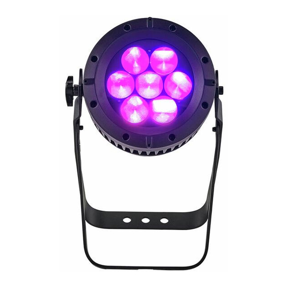
APPENDIX
5.1 MAINTENANCE
NO
1
Hanging bracket
2
Hanging bracket
3
Adjusting stainless steel knob
4
Head casing front section
5
Waterproof gasket
6
Tempered glass
7
Shading plate
8
3.5 degree frosted flakes
9
Magnetic stopper sensor
10
Optical wheel
11
X axis drive team
12
Optical stopper sensor
13
Connect piece
14
Magnetic stopper sensor
NO
15
Power Supply (PS)
16
Adaptor PCB
17
Driver board
18
Base plastic cover
19
Display board
20
XLR 5 cores socket (male)
21
XLR 5 cores socket (female)
22
XLR 3 cores socket (female)
23
XLR 3 cores socket (male)
24
PS socket (male)
25
PS socket (male)
26
Stepping motor
27
Reflective bowl
28
Focus cover
E 20
TourLED Pro
28 Zoom
Bedienungsanleitung
IP 20: led22425
IP 66: led22420
Advertisement
Table of Contents

Related Manuals for Expolite TourLED Pro 28 Zoom


Summary of Contents for Expolite TourLED Pro 28 Zoom
- Page 1 APPENDIX 5.1 MAINTENANCE TourLED Pro 28 Zoom Bedienungsanleitung Hanging bracket Power Supply (PS) Adaptor PCB Hanging bracket Adjusting stainless steel knob Driver board Head casing front section Base plastic cover Waterproof gasket Display board Tempered glass XLR 5 cores socket (male) Shading plate XLR 5 cores socket (female) XLR 3 cores socket (female)
- Page 2 CHANNEL VALUE FUNCTION 1 Allgemeine Produktinformationen WHITE3£4200K WHITE4£4900K Technische Daten WHITE5£5600K WHITE6£5900K LED MODULE WHITE7£6500K WHITE8£7200K Umgebungs- Leistg WHITE9£8000K Type Abmessungen Model Spannung temperatur in W in mm WHITE10£8500K WHITE11£10000K RGBW:12Wx7 375x283x236 STROBE NO FUNCTION AC100~240V -20~45 ١~Hz٢٠ 50/60Hz AUTO RGBW:12Wx7 325x283x236 NO FUNCTION...
- Page 3 1.2 SICHERHEITSHINWEISE FULL WICHTIG! CHANNEL VALUE FUNCTION MASTER DIMMER Dieses Produkt darf nur von qualifiziertem Fachpersonal installiert werden Arbeiten am Gerät dürfen nur von qualifizierten Servicekräften vorgenommen MASTER DIMMER FINE werden RED1 Ein Mindestabstand von 0.5m zur nächsten Oberfläche muss eingehalten werden RED FINE1 Das Produkt darf nur in gut belüftetenRäumen betrieben werden...
-
Page 4: Installation
2 INSTALLATION AR2.Z Befestigung CHANNEL VALUE FUNCTION Hängend MASTER DIMMER Das Gerät kann an dem Haltebügel hängend montiert werden. Hierzu muss eine geeignete Befestigung wie eine Traversenschelle benutzt GREEN werden. Bitte achten Sie auf geltende BLUE Vorschriften zur Sicherung wie das Anschlagen eines Sicherungsseiles. - Page 5 Einstellungen im Displaymenü AR2.D 3.1 DISPLAY BEDIENUNG CHANNEL VALUE FUNCTION Weiter zum nächsten Menü. MENU Auswahl des aktuellen Punktes. ENTER MASTER DIMMER Scrollen durch das Menü oder erhöhen von Werten. Scrollen durch das Menü oder senken GREEN von Werten. MENU ENTER DOWN BLUE...
- Page 6 ARC.1 CHANNEL VALUE FUNCTION UPLD PASS SEND REST PASS REST COLR RGBW GREEN DIMX DIM4 DIM3 DIM2 BLUE DIM1 DERR SAVE BLAK SLCK ZOOM BASE POS1 AR1.D POS2 CAL1 WH.01 R.(0~255) **** CHANNEL VALUE FUNCTION GREN G.(0~255) BLUE B.(0~255) MASTER DIMMER WHIT W.(0~255) WH.11...
- Page 7 3.21 Einstellen statischer Farben CHANNEL VALUE FUNCTION MENU STAT R.(0~255) GREN G.(0~255) STROBE BLUE B.(0~255) NO FUNCTION WHIT W.(0~255) ZOOM Z.(0~255) ١~Hz٢٠ STRB S.(0~20) AUTO ¡ Combine ¡Red¡, ¡Green¡, ¡Blue¡, ¡White¡ and ¡Zoom¡ to NO FUNCTION create an infinite range of colors (0-255) AUTO 1 ¡...
- Page 8 3.25 PERSONALITY TR16 MENU TOUR PERS TR16 CHANNEL VALUE FUNCTION ARC.1 AR1.D ARC.2 MASTER DIMMER AR2.D AR2.S MASTER DIMMER FINE AR2.Z FULL RED FINE Die gewünschte DMX-Personality einstellen GREEN GREEN FINE 3.26 Editieren der Benutzerprogramme BLUE MENU R.(0~255) EDIT PR.01 SC.01 GREN G.(0~255)
- Page 9 3.27 Zusatzeinstellungen CHANNEL VALUE FUNCTION MENU WHITE ٧: ٦٥٠٠K PASS UPLD SEND WHITE ٨: ٧٢٠٠K REST PASS REST COLR WHITE ٩: ٨٠٠٠K WHITE ١٠: ٨٥٠٠K RGBW DIMX DIM4 WHITE ١١: ١٠٠٠٠K DIM3 DIM2 STROBE DIM1 NO FUNCTION O F F DERR SAVE ١~Hz٢٠...
-
Page 10: Using A Dmx512 Controller
3.28 Weißabgleich und Kalibrierung 4 USING A DMX512 CONTROLLER Um in das Kalibrierungsmenü zu gelangen muss das Passwort CHANNEL ASSIGNMENT < UP + DOWN + UP + DOWN > eingegeben werden ¡ Note: This product have three DMX512 channel configuration: ¡TOUR¡,¡TR16¡... -
Page 11: Zoom Range
4 Steuerung über DMX-512 BALANCE PARAMETERS AND CORRECTION 3.28 MENU DISPLAY Kanalbelegung Press ¡MENU ¡ button to enter the password confirmation, to enter the correct password < UP + DOWN + UP + DOWN > Hinweis: Dieses Gerät verfügt über verschiedene DMX-Modi die im Menü Key, press the ¡MENU ¡... -
Page 12: Special Settings
3.27 SPECIAL SETTINGS CHANNEL VALUE FUNCTION MENU WHITE ٧: ٦٥٠٠K WHITE ٨: ٧٢٠٠K UPLD PASS SEND REST PASS REST WHITE ٩: ٨٠٠٠K COLR WHITE ١٠: ٨٥٠٠K RGBW WHITE ١١: ١٠٠٠٠K DIMX DIM4 DIM3 STROBE DIM2 NO FUNCTION DIM1 O F F ١~Hz٢٠... -
Page 13: Editing Custom Programs
3.25 PERSONALITY TR16 MENU TOUR PERS TR16 ARC.1 CHANNEL VALUE FUNCTION AR1.D ARC.2 MASTER DIMMER AR2.D AR2.S MASTER DIMMER FINE AR2.Z FULL ¡ Enter the¡PERSONALITY¡mode to select DMX mode:¡ TOUR ¡ RED FINE ¡ TR16 , ARC.1 ¡ ¡ ¡£¡ AR1.D ¡£¡... - Page 14 3.21 EDIT STATIC COLOUR MENU STAT R.(0~255) CHANNEL VALUE FUNCTION GREN G.(0~255) BLUE B.(0~255) STROBE WHIT W.(0~255) NO FUNCTION ZOOM Z.(0~255) STRB S.(0~20) ١~Hz٢٠ AUTO ¡ Combine ¡Red¡, ¡Green¡, ¡Blue¡, ¡White¡ and ¡Zoom¡ to NO FUNCTION create an infinite range of colors (0-255) AUTO 1 ¡...
- Page 15 ARC.1 UPLD PASS SEND CHANNEL VALUE FUNCTION REST PASS REST COLR RGBW DIMX DIM4 GREEN DIM3 DIM2 DIM1 BLUE DERR SAVE BLAK SLCK ZOOM BASE POS1 POS2 AR1.D CAL1 WH.01 R.(0~255) **** GREN G.(0~255) CHANNEL VALUE FUNCTION BLUE B.(0~255) WHIT W.(0~255) MASTER DIMMER WH.11...
-
Page 16: Display Panel Operation
DISPLAY PANEL OPERATION 3.1 DISPLAY OPERATION AR2.D CHANNEL VALUE FUNCTION ¡ MENU£ £ BACK ¡ ENTER£ ENTER OR SAVE £ MASTER DIMMER ¡ DOWN£ DOWN £ ¡ UP£ £ GREEN MENU ENTER DOWN MENU MAP BLUE MENU STAT R.(0~255) WHITE GREN G.(0~255) BLUE... -
Page 17: Power Connections
2 INSTALLATION MOUNTING AR2.Z CHANNEL VALUE FUNCTION HANGING MASTER DIMMER The fixture can be mounted in a hanging position using the supporting bracket. The bracket should be secured to the mounting truss or GREEN structure using a standard mounting clamp. Please note that when hanging BLUE the unit a safety cable should also be used. -
Page 18: Safety Warning
1.2 SAFETY WARNING FULL CHANNEL VALUE FUNCTION IMPORTANT£ MASTER DIMMER ¡This product must be installed by a qualified professional. MASTER DIMMER FINE ¡All maintenance must be carried out by a qualified electrician. RED1 ¡A minimum distance of 0.5m must be maintained between the equipment and a combustible surface. -
Page 19: Product (General)
CHANNEL VALUE FUNCTION 1 PRODUCT (GENERAL) WHITE3£4200K WHITE4£4900K TECHNICAL SPECIFICATIONS WHITE5£5600K LED MODULE WHITE6£5900K WHITE7£6500K WHITE8£7200K Weight Operation Power Type Dimensions 2 WHITE9£8000K Model Voltage Temperature (KG) £W£ £mm£ WHITE10£8500K WHITE11£10000K RGBW:12Wx7 375x283x236 ¢ STROBE NO FUNCTION AC100~240V -20~45 ١~Hz٢٠ 50/60Hz AUTO RGBW:12Wx7... - Page 20 Anhang 5.1 Explosionszeichnung TourLED Pro 28 Zoom User Manual Hanging bracket Power Supply (PS) Hanging bracket Adaptor PCB Adjusting stainless steel knob Driver board Base plastic cover Head casing front section Waterproof gasket Display board Tempered glass XLR 5 cores socket (male) Shading plate XLR 5 cores socket (female) XLR 3 cores socket (female)
Need help?
Do you have a question about the TourLED Pro 28 Zoom and is the answer not in the manual?
Questions and answers