Advertisement
Quick Links
Advertisement

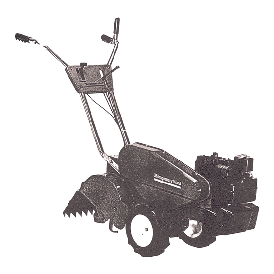
Summary of Contents for Montgomery Ward TMO-39083A
- Page 2 Operation. Controls. Adjustments. Assembly. Safe Operation UseY Practices. Tiller NOTICE: A data plate with the model number and serial numbers Record these numbers in the spaces Check Spark Plug Wire Check Crankcase Oil Level Check Fuel Tank Check Air Cleaner...
- Page 3 9. Do not start the engine unless is in the neutral (N) position. 10. Do not stand in front of the tiller while starting the engine. 11. Do not place feet and hands tines when...
- Page 4 3. NOTE For clarity, figure 3 was taken with., "-.-:"",,,~: tiller raised on end. It is not neces~~;: sary to raise the tiller. GAS- Long -'=- --=.:;..-:: ""-- pack...
-
Page 5: Handle Assembly
Mount s,de shields (AB) over the weld bolts on the end cover assemblies. -washers HANDLE 1. Place right handle (AA) in position side of the tiller. belleville bracket. and lock washers 2. Repeat step 1 for left handle side of the tiller. - Page 6 FIGURE 7. FIGURE 8. Mount the handle panel (AC) to the handles. Secure with carriage -(N) and hex nuts (0). See figure 7. NOTE To align holes panel the handle, necessary loosen brackets which are mounted to the back handles tapping screws.
- Page 7 FIGURE 10. FIGURE 11. FIGURE 12. 2. Hook the "Z" end of tine clutch hole in tine clutch lever. 3. With the clutch lever released position), adjust the bottom bracket so there is only a slight slack in the control wire.
-
Page 8: Controls-Location
Service engine with oil and gasoline before checking adjustment. engine manual packed with your tiller. 8. Check the adjustment follows. Place the unit against a solid object (wall, fence, etc.). With the tine clutch lever released and the drive clutch... -
Page 9: Before Starting
1. Move throttle 2. Disconnect vent accidentally unattended. Tilling can be adjusted figure figure spark against 1. When using the tiller for the first time, use the second in the tilling STARTED. OR BEING position. lever in "START" FIGURE 16. position. - Page 10 ADJUSTMENTS HANDLE bar and side The handle may be placed in one of nine different positions. passes three height positions, to be in line with the tiller, depth may be right so the operator (use bottom tilled soil. deepest tilling...
- Page 11 Disconnect the spark plug wire and ground it against the engine performing repairs IMPORTANT If for any reason the tines moved from the tiller, be certain tines are reassembled so that the sharp edge of the tines soil first. Refer item one under "Operation."...
- Page 12 Dirt, leaves and other not be left to accumulate around the cooling or the engine or on any part of the tiller. Clean the underside of the tine shield dirt washes off the tines easier...
- Page 13 Wheel Chain Case Pulley / 1-1 Small I " < ...~ : -;') '",. ~~,"'~ --'.'- Reverse Drive " FIGURE 23. To remove the forward drive belt, proceed follows. A. Loosen (do not remove) the hex nut at the top of the wire belt keeper. B.
- Page 14 See figure 27. If the tiller is to be inoperative than 30 days, the following precautions mended. Keep your tiller in a weatherproof, area.
- Page 15 SYMPTOM Engine fails to start Hard starting or loss of power overheats Controls do not engage NOTE: For repairs beyond the minor adjustments POSSIBLE CAUSE(S) 1. Check fuel tank for gas.2. Spark plug lead wire disconnected.3. Faulty spark plug. 1. Spark plug wire loose. 2.
- Page 16 ;.- 60-;1' 18\ sh " \'~ i " :/1f ", " '" ---52 ""'53 Wire Assembled in Upper Hole on Model TMO-39083A Wire Assembled in Lower Hole on Model TMO.39084A (\=:J~~3 17" / J.9 -:;'/ (, .38 ~ -" -4') "...
- Page 17 714-0507 Cotter Pin 3/32" Dia. x 3/4"* 725-0157 Cable Tie 747-0432 Tiller Flap Aod (TM 0-39084A) Tiller Flap Aod (TMO-39083A) 14989 End Cover Ass'y.-L.H. 14990 End Cover Ass'y.-A.H. (Not Shown) 736-0242 Bell-Wash. 5/16" 1.0. 712-0267 Hex Nut 5/16-18 Thd.* 15390...
- Page 18 P ARTlcOLOR DESCRIPTION CODE Hex Cent. L-Nut 3/8-16 Thd. Hex Bolt 5/16-18 x .75" Lg.* 747-0507 Belt Keeper (TMO-39084A) 747-0506 I Belt Keeper (TMO-39083A) Hex Nut V4-20 Thd.* 712-0287 Bell-Wash. .265" 1.0. x .75" 736-0270 0.0. Idler Brkt. Ass'y. (Wheel Reverse) Shld.
- Page 19 736-0185 I:-I-Wash. .406" I.D. x .750" O.D. Side Plate Ass'y. Set Scr. 1/4-28 x .25" Lg. L-Wash. 5/16" I.D.* Hex Bolt 1/4-20 x 1.25" Lg.* (TMO-39083A) 710-0237 Hex Bolt 5/16-24 x .62" Lg. (TM 0-39083A) Bell-Wash. 5/16" I.D. PART Tines...
- Page 20 Chain Case Ass'y. Tines 784-0104 Chain Case Ass'y. Wheels (TMO-39084A) 784-0105 Chain Case Ass'y. Wheels (TMO-39083A) 710-0189 Hex Bolt 5/16-18 x 3.00" Lg.* 710-0118 Hex Bolt 5/16-18 x .75" Lg.* 14973 Engine Mounting I -Wash. 5/16" I.D.* 736-0119 ~ 712-0267 Hex Nut 5/16-18 Thd.*...
- Page 22 & Hub Ass'y. 113-0326 #420 Chain V2 Pitch x 28 Links Endless 14 1784-0126 Wheel Shaft Ass'y. (TMO-39084A) 784-0125 Wheel Shaft Ass'y. (TMO-39083A) Flange Bearing 1 741-0227 FI-Wash. .88" 1.0. x 1.5" 736-0265 0.0. x .03 750-0354 Spacer 7/8" 1.0. x 13/4" 0.0.
- Page 23 Heavy Duty Rear Tine Garden Tiller Attachments Available for All-Season 31-0110 8" Furrower Opener 31-0144 "V".Bar Cultivating with 31-0178 adapter) Kit Includes: "V"-Bar Frame, 4-Point Cultivating Tines, Hiller/Furrower, Wheels (Pair). 31-0145 Depth Stake Cultivating used with 31-0178 adapter) Kit Includes: 8" Furrower Opener, 15"...
- Page 24 REPLACEMENT The merchandise carefully quality dependable operation. However, like all mechanical merchan-dise, parts assistance or parts, please contact or write your nearest Wards Retail Store, Central Service Center, Catalog Store or Catalog House. Provide the following: 1. Model, serial number and all of the other data shown on the model plate.2.

Need help?
Do you have a question about the TMO-39083A and is the answer not in the manual?
Questions and answers