Table of Contents
Advertisement
Quick Links
Advertisement
Table of Contents

Related Manuals for ABS ABSFBM-120T


Summary of Contents for ABS ABSFBM-120T
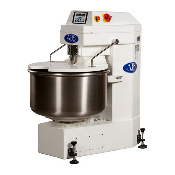
- Page 1 OWNER’S MANUAL ABSFBM-120T Spiral Mixer...
-
Page 2: Table Of Contents
CONTENTS Introduction••••••••••••••••••••••••••••••••••••••••••••••••••••••••••••••••••••••••••(2) Installation & Commissioning•••••••••••••••••••••••••••••••••••••••••••••••••••(3) Operation•••••••••••••••••••••••••••••••••••••••••••••••••••••••••••••••••••••••••••••(4) Caution••••••••••••••••••••••••••••••••••••••••••••••••••••••••••••••••••••••••••••••••(8) Cleaning & Maintenance••••••••••••••••••••••••••••••••••••••••••••••••••••••••••(9) Trouble Shooting••••••••••••••••••••••••••••••••••••••••••••••••••••••••••••••••••(10) Parts List••••••••••••••••••••••••••••••••••••••••••••••••••••••••••••••••••••••••••••(12) Wiring Diagram••••••••••••••••••••••••••••••••••••••••••••••••••••••••••••••••••••(20) -
Page 3: Introduction
INTRODUCTION Introduction The ABSFBM-120T is a Spiral Mixer with a Three-Timer control panel and two motors; one motor drives the hook while the other drives the bowl. The hook and bowl are made of stainless steel for long life and ease of cleaning. -
Page 4: Installation & Commissioning
INSTALLATION AND COMMISSIONING Installation The machine is ready for installation. After uncrating your spiral mixer, inspect the machine for any damage that might have occurred during shipment. Report any damage to us before proceeding. Never attempt to operate this mixer with damaged parts. 1). -
Page 5: Operation
OPERATION Control Panel 1. Timers On top of the operation panel, there are three timers: Timer , is for slow speed; Timer Ⅲ is for fast speed. Each Timer has three digits. The unit of A and B is minute while C is 10 seconds, for example: 0.1 is 10 seconds, 1.2 is 1 minute and 20 seconds. - Page 6 OPERATION 2. Indication lights Indication lights indicate the running state of the spiral mixer: A). AUTO/MANUAL lights: When “AUTO” lamp lights up, spiral mixer is in AUTO operation. When “MANU” lamp lights up, spiral mixer is in MANUAL operation. B). Bowl direction lights: When lamp lights up, the bowl is in forward direction.
- Page 7 OPERATION Operation Preparation Check the machine’s bowl is clear of all foreign objects, all switches are off and work area should be clear of bystanders. Safety guard should be raised and pushed back fully against stop to avoid it falling onto operator. The mixer has safety interlocks to prevent mixer operation when the safety guard is lifted.
- Page 8 OPERATION 2. Manual operation A). Press button until the “MANU” lamp lights up. B). Press buttons to select the desired bowl direction. C). Press to start. D). Press button when you want to stop the machine. The timer will not function under manual operation. The mixer will always start with slow speed even if you have selected fast speed to start.
-
Page 9: Caution
CAUTION 1. Use the machine with great care and never be distracted. 2. Do not wear loose fitting clothes or clothing with wide or open sleeves. 3. Do not remove, cover or alter the warning stickers or machine safety covers placed on the machine body. 4. -
Page 10: Cleaning & Maintenance
CLEANING AND MAINTENANCE 1. Brush off all external surfaces. Use a soft brush and work from the top to the bottom. 2. Remove all old dough using a plastic scraper. 3. Scrape the mixing bowl, the breaker bar, the dough spiral, under the bowl cover inside the mixing bowl, and behind the mixing bowl. -
Page 11: Trouble Shooting
TROUBLE SHOOTING Fault Possible Cause Remedy Plug in and switch Not plugged in. The main switch is “off”. Turn the switch on. The bowl safety cover is Place down The mixer does not open. position. operate /start. The mixer overload has Contact supervisor / been tripped. - Page 12 TROUBLE SHOOTING Fault Possible Cause Remedy Switch off power at main switch. Isolate mixer unplugging. The mixer does not Electrical / mechanical stop malfunction. Attach danger tag to machine. Contact authorized service agent. Excessive water used in Review recipe and dough (human error).
-
Page 13: Parts List
PARTS LIST... - Page 14 PARTS LIST...
- Page 15 PARTS LIST...
- Page 16 PARTS LIST...
- Page 17 PARTS LIST...
- Page 18 PARTS LIST Parts Number Parts Code Parts Name Specification SM120T001 16JCQCN18-1 Contactor SM120T002 16JCQCN16-1 Contactor SM120T003 16LSLCI-18 Mechanical Connector SM120T004 16BXSZD Fuse Seat SM120T005 16JDQMY4-24V Relay AC 24V SM120T006 16JDQMY2-110V Relay AC 110V SM120T007 16BXSG111B Fuse Cover 380V-220V/110V SM120T008 16BYQJBK100-1 Transformer 30W-26V 70W SM120T009...
- Page 19 PARTS LIST 16KGLBE101 Manual Switch SM120T037 16KGLZA-BD3 Manual Switch Seat SM120T038 13M444-12T-01 Machine Top Cover SM120T039 11M750-12TT Safety Grids SM120T040 11M620-12T Bowl SM120T041 15BSLHY01 Outrigger Screw SM120T042 14D9016150-01 Foot Pad SM120T043 13M802-12T Safety Cover 380V-50HZ-3PH SM120T044 16MDL120TS-1 Top Motor 10KW 4/8P 230/400V-50/60H SM120T045 16MDL120AX-12...
- Page 20 PARTS LIST Adjusting Wheel SM120T071 14M710-01 Microswitch SM120T072 16KGLMEA9112G Microswitch SM120T073 13M801-12T Safety Cover SM120T074 13M770-03 Safety Cover SM120T075 14M250-12T-03 Pulley SM120T076 14M190-12T-03 Top Transmission Shaft SM120T077 14M240-12T-02 Bush SM120T078 15ZCL3209VV Bearing 3209VV SM120T079 15ZCL51104 Bearing 51104 SM120T080 14M170-02 Shaft for Front Castor SM120T081 14M150-03 Bracket for Front Castor...
-
Page 21: Wiring Diagram
WIRING DIAGRAM...
Need help?
Do you have a question about the ABSFBM-120T and is the answer not in the manual?
Questions and answers