Table of Contents
Advertisement
Quick Links
Advertisement
Table of Contents
Troubleshooting

Subscribe to Our Youtube Channel
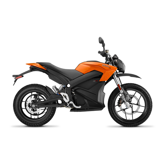
Related Manuals for Zero Motorcycles 2016 ZERO S


Summary of Contents for Zero Motorcycles 2016 ZERO S
- Page 1 ™ ZERO S ZERO SR ™ ™ ZERO DS ™ ZERO DSR 2016 OWNER’S MANUAL...
-
Page 3: Table Of Contents
Introduction ............ 1.1 Safety Information ......... 2.1 Introduction..............1.1 General Safety Precautions ........2.1 An Important Message From Zero Motorcycles ..1.1 General Safety Precautions ........2.1 About This Manual ............ 1.1 Important Operating Information ....... 2.2 Useful Information For Safe Riding ......1.2 Location of Important Labels ........ - Page 4 Charging and Power Pack Information..5.1 Cleaning..............6.22 Power Pack and Charging ...........5.1 Parking and Long Term Storage......6.23 Power Pack..............5.1 Zero Motorcycles Accessories ........ 6.23 On-Board Power Pack Charger .........5.2 Fuses ..............6.23 Charging the Power Pack ..........5.3 Quick Charging (Off-Board Accessory Charger)..5.5 Troubleshooting ..........
- Page 5 What Other Limitations Or Disclaimers Apply To This Limited Warranty ..........9.5 What Are Your Responsibilities As A Customer? ..9.6 What Will Zero Motorcycles Do Under This Limited Warranty? ..............9.7 How Does This Limited Warranty Relate To State Law? .................
-
Page 7: Introduction
Introduction Introduction Introduction An Important Message From Zero Motorcycles About This Manual Congratulations and thank you for purchasing the 2016 This manual covers the following motorcycles (standard Zero S, Zero SR, Zero DS, or Zero DSR electric features and equipment include Integrated Z-Force®... -
Page 8: Useful Information For Safe Riding
Introduction Useful Information For Safe Riding Plug in Your Z-Force Power Pack™ ® This manual contains the word WARNING to indicate CAUTION: Proper care of the motorcycle’s power pack is something that could hurt you or others. It also contains essential! When not in use, the power pack should be left the word CAUTION to indicate things that could damage on the charger even if fully charged. -
Page 9: Identification Numbers
Identification Numbers Owner Information Identification Numbers Record information pertaining to your motorcycle here. When contacting your dealer, you may need to provide this information. -
Page 10: Power Pack Serial Number
Identification Numbers Power Pack Serial Number Vehicle Identification Number (VIN) The Power Pack serial number is located on the upper The VIN is a 17-digit number stamped on the head tube of front left of the power pack. the frame. Do not alter or remove this number as it is the legal identifier for your motorcycle. - Page 11 Identification Numbers VIN Breakdown The following breakdown of the VIN will help you understand the significance of each digit or character in case you need to reference it when contacting Zero Motorcycles or ordering parts.
-
Page 12: General Information
General Information Emissions Information Vehicle Range General Information The Zero S/SR/DS/DSR electric motorcycle is a true The range of an electric vehicle is defined as the distance freeway-capable zero-emissions vehicle under California the vehicle travels on a single full charge of the power Air Resources Board (CARB), U.S. -
Page 13: Maximizing Your Range
General Information Reported motorcycle range values are measured using Maximizing Your Range two different types of industry standard test procedures: Range varies in electric motorcycles similarly to how it 1. “City”: This range test is specified to determine riding varies in gas motorcycles. However, the big difference during “stop-and-go”... - Page 14 General Information...
- Page 15 General Information...
-
Page 16: Transporting
General Information Transporting It is recommended that the motorcycle be tied-down using ratchet straps while it is being transported. Place the ratchet straps around a frame contact point. Soft straps must be used to prevent scratches or other damage. Use two ratchet straps in the front and two in the rear. The tie down straps should be at a 45°... -
Page 17: General Safety Precautions
General Safety Precautions • Prior to each use the rider must check everything in the Safety Information General Safety Precautions General Safety Precautions “every ride” column of the maintenance schedule on • This is a performance motorcycle and should be page 6.2, and the charge level of the power pack as treated with extreme caution. -
Page 18: Important Operating Information
• Failure to follow power pack storage and charging • Turn the motor stop switch OFF when backing up or instructions as described in this Zero Motorcycles pushing the motorcycle while dismounted. Owner’s Manual may void the warranty of your Zero •... -
Page 19: Location Of Important Labels
Location of Important Labels Location of Important Labels Location of Important Labels The vehicle could contain the following information for both North American and European models: A. VECI (Vehicle Emission Control Information) label C. VIN label (North America) - certification label shown B. - Page 20 Location of Important Labels High Voltage Warning Label Affixed to battery...
-
Page 21: Controls And Components
Controls and Components Controls and Components Controls and Components THIS PAGE INTENTIONALLY LEFT BLANK... -
Page 22: Motorcycle Controls
Controls and Components Motorcycle Controls... - Page 23 Controls and Components A. Mirrors G. Front Brake Lever This motorcycle is equipped with convex mirrors. A For description and operation, see “Handlebar convex mirror has a curved surface. Convex mirrors Controls”, on page 3-16. offer a greater field of view than a similar flat mirror. H.
-
Page 24: Left Side View
Controls and Components Left Side View... - Page 25 Controls and Components A. Headlight F. Kickstand The kickstand swings out from the side and supports • For headlight operation, see “Handlebar Controls”, on the motorcycle when parked. The key switch should page 3-16. be in the OFF position when parked. •...
-
Page 26: Right Side View
Controls and Components Right Side View... - Page 27 Controls and Components A. Rear Brake Fluid Reservoir See “Rear Brake Fluid Reservoir”, on page 6-11. B. Auxiliary Power Pack Charging Connection For description and operation, see “Quick Charging (Off-Board Accessory Charger)”, on page 5-5. The auxiliary connector is located above the motor. C.
-
Page 28: Dash Overview
Controls and Components Dash Overview... - Page 29 Controls and Components A. Adjust Button (ADJ) the rider using the performance level mode button located on the right handlebar control assembly. See See “Dash Settings”, on page 3-12. “Performance Level Mode Button”, on page 3-20. B. Select Button (SEL) I.
-
Page 30: Warning Indicator Lights
Controls and Components Warning Indicator Lights 3.10... - Page 31 Controls and Components A. Left Indicator Turn Signal E. ABS (Anti-Lock Brake System) Indicator An arrow on the lower dash flashes green The indicator illuminates when the key is in the same direction as selected by the in the ON position. The light will extinguish turn signal switch.
-
Page 32: Dash Settings
Controls and Components Dash Settings Displays A&B Display A The displays on the dash can be customized to your To select Display A with the dash in its normal operating personal preferences by using the ADJ (Adjust) and SEL mode, momentarily press the SEL button once. Press the (Select) buttons. - Page 33 Controls and Components Display B Setting the Clock To select Display B with the dash in its normal operating mode, momentarily press the SEL button twice. Press the ADJ button to toggle through the following fields: • Trip 2 Odometer - Displays individual trip mileage and is reset by pressing and holding the ADJ button for 2 seconds.
- Page 34 Controls and Components Unit Display - Speed Unit Display - Temperature To change the units that speed is shown in: To change the units that the temperature display is shown: 1. With the dash in its normal operating mode press and 1.
-
Page 35: Smartphone Application
Controls and Components Smartphone Application Bluetooth Pairing ® You can download a smartphone application that lets you The following steps must be taken to properly pair a perform the following tasks related to your motorcycle: Bluetooth®-equipped smartphone with your motorcycle. •... -
Page 36: Handlebar Controls
Controls and Components Handlebar Controls 3.16... - Page 37 Controls and Components A. Headlight High/Low Beam Switch E. Throttle Control When the switch is pushed, the headlight Twist the throttle in a counter-clockwise rotation (A) to changes from low beam to high beam. It energize the motor and start the motorcycle in a stays in the selected position until it is forward direction.
- Page 38 Controls and Components F. Motor Stop Switch H. Hazard Warning Flasher Switch When the top of the switch (A) is pressed, it cuts off When the top of the switch is pressed, the turn signals power to the run signal. The motor controller remains flash to warn other drivers of situations, which include in this state until the bottom portion of the switch (B) is needing to stop or park under emergency conditions.
- Page 39 Controls and Components J. Horn Button When the key is in the ON position, the horn (A) sounds when the button is pressed. Electric vehicles run quietly; the horn can be used to warn pedestrians or other motorists of your presence. 3.19...
-
Page 40: Performance Level Mode Button
Controls and Components Performance Level Mode Button The SPORT selection causes the motorcycle to accelerate at a significantly faster rate. This position is recommended for advanced riders. The CUSTOM selection has customizable performance settings by using the smartphone application (refer to “Smartphone Application”, on page 3-15). -
Page 41: Front Brake Lever Adjuster
Controls and Components Front Brake Lever Adjuster The position of the front brake lever can be adjusted by turning the adjustment knob (A) located on the master cylinder assembly. Turning the knob clockwise or counter-clockwise will adjust the distance between the lever and the throttle control. -
Page 42: Tank Bag
Controls and Components Tank Bag Power Tank (if equipped) Depending on specification, your Zero motorcycle may be Your Zero motorcycle may be equipped with a dealer- equipped with a tank bag for additional storage. You can installed optional equipment Power Tank in place of the remove the tank bag by pulling upwards on its sides. -
Page 43: Charge Tank (If Equipped)
Controls and Components Charge Tank (if equipped) Your Zero motorcycle may be equipped with a dealer- installed Charge Tank. This is optional equipment installed in place of the tank storage area. The Charge Tank has a J1772 charge connector, which is concealed by a hinged protective rubber cover. - Page 44 Notes 3.24...
-
Page 45: General Operation
General Operation • Tires. Check both tires for condition and tread depth. Starting and Operating General Operation General Operation Check cold tire pressure frequently. Check for damage This section describes several items you should examine and alignment. Maintain correct tire pressure as before operation. -
Page 46: Key Switch/Steering Lock Positions
General Operation Key Switch/Steering Lock Positions Steering Lock Using the steering lock when parked prevents unauthorized use and helps prevent theft. To operate the steering lock: 1. Turn the handlebar all the way to the left. 2. With the key in the OFF position, push the key down and turn the key counter-clockwise. - Page 47 General Operation OFF Position This position is used to turn the motorcycle OFF, disabling the electrical system. ON Position This position is used for operating the motorcycle. In this position the following sequence occurs: • Lights turn ON • Dash display turns ON...
-
Page 48: Operating Your Motorcycle
General Operation Operating Your Motorcycle without locking the wheels. Your Zero motorcycle is a light- weight performance product and therefore practice is This section describes how to safely operate your strongly recommended to perfect safe emergency stops. motorcycle. Stopping Your Motorcycle Starting To stop your motorcycle: 1. - Page 49 Temperature Indicator reduction, you can choose to slow down a bit until the indicator stops flashing. Zero Motorcycles has developed the most advanced • Stage 2, if temperature continues to build, the indicator passively air-cooled electric powertrain for your Zero...
-
Page 50: Abs (Anti-Lock Brake System)
General Operation ABS (Anti-lock Brake System) WARNING! ABS prevents the wheels from locking, therefore maximizing the effectiveness of the braking system in emergencies and when riding on slippery surfaces. The potentially shorter braking distances ABS allows under certain conditions are not a substitute for good riding practices. - Page 51 ABS 1. Disconnect external charge cables. system repaired. If there are no dealers in you area, call Zero Motorcycles Customer Service. See “Customer 2. Wait for the dash display to turn off completely. Assistance”, on page 9.10...
- Page 52 General Operation WARNING! The ABS computer compares the relative speed of the front and rear wheels. Using tires other than those specified by Zero Motorcycles can adversely affect the ABS functionality and stopping distance of your motorcycle. WARNING! If the ABS warning indicator is illuminated when traveling at speeds exceeding 3 mph (5 km/h), the ABS is not functioning.
-
Page 53: Front Suspension Adjustment
General Operation Front Suspension Adjustment 3. Record this measurement (this is the measurement referred to as M1). A shock has two main actions: compression when the shock gets loaded, and rebound when the shock returns back to full length. Compression damping is the adjustment that determines how fast or slow the fork compresses. - Page 54 General Operation 9. Record this measurement (this is the measurement Example: referred to as M2). Measurement Operator Value 4.13 in (105 mm) 2.36 in (60 mm) 1.77 in (45 mm) The total sag is 1.77 in (45 mm). Refer to the chart below for the correct sag.
- Page 55 General Operation Spring Preload Adjustment The spring preload is adjusted by turning the 19 mm anodized hex nut (B) located on top of the fork spring. Note: When adjusting preload, always start from the minimum setting and adjust each fork leg evenly. •...
- Page 56 General Operation Compression Damping too slow will pack-up (feel harsh over consecutive bumps), while compression that is set too fast will cause the fork to The compression damping is adjusted by turning a screw bottom out harshly. If the fork is bottoming out, turn the on the bottom of each fork leg.
-
Page 57: Rear Shock Adjustment
General Operation Rear Shock Adjustment Measuring Preload Obtaining the correct rear spring preload (sag) is critical for proper handling. The spring preload must be set to match the weight of the rider. The spring is preloaded for a 180 lb (82 kg) rider. - Page 58 General Operation Example: Measurement Operator Value 23.62 in (600 mm) 21.65 in (550 mm) 1.97 in (50 mm) The total sag is 1.97 in (50 mm). Refer to the chart below for the correct sag. If the sag is not correct, the spring preload should be adjusted.
- Page 59 General Operation Spring Preload Adjustment Rebound Adjustment The rebound adjuster knob (A) is at the bottom of the 1. Clean any dirt or debris from the slots of the shock shock. It has 8 stages of adjustment. Printed on the knob is adjusting collar (A).
- Page 60 General Operation Compression Adjustment The compression adjustment knob is at the top of the shock. It has 18 stages of adjustment. Printed on the knob is “H” meaning Hard (slower compression) and “S” meaning Soft (faster compression). Turn the adjuster clockwise for a harder ride (slower compression).
- Page 61 General Operation Factory Supplied Rear Suspension Settings The following information will allow you to adjust the rear suspension back to the factory settings the motorcycle was originally supplied with. S & SR Models ADJUSTMENT SETTING Rear Shock Compression 12 clicks out from fully closed Rear Shock Rebound 8 clicks out from fully closed Rear Shock Spring Preload...
- Page 62 Notes 4.18...
-
Page 63: Power Pack And Charging
Power Pack and Charging Power Pack The power pack must be charged within 24 hours if fully Charging and Power Pack Information Power Pack and Charging discharged, and charged within 90 days if stored fully The battery is located within the power pack and requires charged. -
Page 64: On-Board Power Pack Charger
Power Pack and Charging • If the power pack terminates the charge before the On-Board Power Pack Charger charger reaches the state previously mentioned, then Keep your power pack connected to the charger when the charger continues to cycle and tops off the power your motorcycle is sitting in storage or if it will be sitting pack until the power pack is removed from the charger, unused for more than 90 days. -
Page 65: Charging The Power Pack
Power Pack and Charging When charging the motorcycle, the LEDs flash from left to Charging the Power Pack right. Then a number of LEDs (from 1 to 4) will illuminate to WARNING! Charge the Zero power pack with the Zero indicate the charge level. -
Page 66: Technical Specifications
Power Pack and Charging To charge using the standard on-board charging Note: AVOID connecting the Zero charger and another equipment: device to a single 120 V AC 15A/20A circuit, as it may become overloaded. Zero chargers draw as much as 1. -
Page 67: Quick Charging (Off-Board Accessory Charger)
Power Pack and Charging Quick Charging (Off-Board Accessory Charger) The “scalable” quick charging feature allows up to four supplemental accessory chargers (in addition to the existing integrated charger) to be connected to the motorcycle. Use of supplemental accessory chargers can reduce the charging time by up to 75%. - Page 68 Power Pack and Charging Using the Quick Charger and the current State of Charge (SOC) should display on the dash. 1. Ensure that the key switch is in the OFF position. 6. Plug in the AC Power Cord to an AC power outlet. 2.
- Page 69 Power Pack and Charging • The charger and BMS are balancing. Quick Charger LED Indicators • The BMS is cutting off the charge because one or more cells have reached maximum voltage. C. 100% Charge The 100% Charge LED is a green indicator. If it is on solid, the charging is complete and the charger will enter maintenance mode.
-
Page 70: Charge Tank (If Equipped)
Power Pack and Charging Charge Tank (if equipped) The Charge Tank is a dealer-installed quick charging accessory. It effectively triples charging speed (compared to the to the Level 1 existing integrated charger) and is designed to work with Level 2 public charging stations operating on the popular J1772 standard. -
Page 71: Public Charging Stations
Level 2 charging station can damage your motorcycle, prevent other components with the optional J1772 Zero Motorcycles charging adapter from working as they should, and/or dramatically reduce accessory (Zero PN: 10-03267). These charging stations the range and/or life expectancy of the power pack. - Page 72 Notes 5.10...
-
Page 73: Maintaining Your Motorcycle
• Perform routine care and maintenance of your electric motorcycle as detailed in this owner’s manual. • Use only Zero approved parts and Zero Motorcycles accessories. • The operator is responsible for learning and obeying all country, federal, state, and local laws governing the operations of an electric motorcycle. -
Page 74: Parts/Maintenance Items
Maintaining Your Motorcycle Parts/Maintenance Items Scheduled Maintenance The proper replacement parts, fluids, and lubricants to use The required maintenance schedule that follows, specifies are listed in the table below. how often you should have your Zero Motorcycle serviced and what items need attention. It is essential to have your PART NUMBER Zero motorcycle serviced as scheduled to maintain safe,... - Page 75 Maintaining Your Motorcycle ITEM ROUTINE EVERY INITIAL INITIAL ODOMETER MILEAGE READING RIDE 600 mi 4K mi 8K mi 12K mi 16K mi 20K mi (1K km) (7K km) (13K km) (19K km) (25K km) (31K km) 1 month 6 months 12 months 18 months 24 months...
- Page 76 Maintaining Your Motorcycle ITEM ROUTINE EVERY INITIAL INITIAL ODOMETER MILEAGE READING RIDE 600 mi 4K mi 8K mi 12K mi 16K mi 20K mi (1K km) (7K km) (13K km) (19K km) (25K km) (31K km) 1 month 6 months 12 months 18 months 24 months...
- Page 77 Maintaining Your Motorcycle ITEM ROUTINE EVERY INITIAL INITIAL ODOMETER MILEAGE READING RIDE 600 mi 4K mi 8K mi 12K mi 16K mi 20K mi (1K km) (7K km) (13K km) (19K km) (25K km) (31K km) 1 month 6 months 12 months 18 months 24 months...
-
Page 78: Component Fasteners
Maintaining Your Motorcycle Component Fasteners Periodically check and tighten the following fasteners on your motorcycle. Torque Table LOCATION ITEM TORQUE NOTES Headlight bolts 8 lb·ft (11 Nm) Use LOCTITE® 242® (or equivalent) Handlebar clamp mount bolts 19 lb·ft (26 Nm) Rear shock mount bolts 40 lb·ft (54 Nm) Seat retaining bolts... - Page 79 Maintaining Your Motorcycle Left Side of Motorcycle Refer to Torque table on page 6.6.
- Page 80 Maintaining Your Motorcycle Right Side of Motorcycle Refer to Torque table on page 6.6.
-
Page 81: Power Pack
Power Pack Power Pack Power Pack CAUTION: You must leave your motorcycle on the charger if you expect it to sit in storage or unused for over 90 days. The power pack must be charged within 24 hours if fully discharged, and charged within 90 days if stored fully charged. -
Page 82: General Maintenance
General Maintenance Brakes Front Brake Fluid Reservoir General Maintenance Inspect the level of the front This section describes how to maintain the brake system brake fluid, visible through the of your Zero S/SR/DS/DSR motorcycle. It covers the ABS reservoir (C). If the fluid level (Anti-lock Brake System), brake pad examples (specific is visibly below the MIN level brake pads for front and rear are shown), and maintaining... - Page 83 General Maintenance Rear Brake Fluid Reservoir Clean any dirt or debris from the cap and reservoir opening (A) before opening the reservoir. The reservoir is located inboard on the frame behind the heel guard. Note: The motorcycle should be in an upright position prior to checking fluid level.
- Page 84 General Maintenance Brake Pad Inspection Brake Pad Replacement The brake pads must be inspected when specified in the Bedding in new brake pads and/or new brake discs is maintenance schedule, see page 6.2. Visually inspect the recommended to ensure proper brake performance and brakes by looking at the remaining brake pad material maximize brake life.
-
Page 85: Suspension
General Maintenance Suspension Front • For maintenance, see Maintenance Schedule on page 6.2. • To adjust the fork, see Suspension Adjustment on page 4.9. Rear WARNING! The shock absorber assembly contains highly pressurized gas. Rear brake pads • Do not attempt to tamper with or open the cylinder or WARNING! With new brake systems or just new pads, the shock. -
Page 86: Wheels And Tires
General Maintenance Wheels And Tires Tire Inflation Inspect both wheels for the following: WARNING! Under-inflation is a common cause of tire failure and may result in severe tire cracking, tread • Bent or cracked rims separation, “blowout,” or unexpected loss of motorcycle •... -
Page 87: Drive Belt
General Maintenance Drive Belt Checking Drive Belt Tension Proper belt tension is essential for optimum operation of The drive belt provides low maintenance and quiet the drive system. operation with minimal stretch. Keep dirt, grease, oil, and Lack of belt tension can lead to “ratcheting.” The teeth of debris off the belt and sprockets.The drive belt tension the belt slide over the teeth of the rear sprocket. - Page 88 General Maintenance Drive Belt Adjustment Procedure Note: Adjust both sides (left and right) equally. 1. Remove key from the key switch. 2. Loosen the rear axle nut (A). 3. Loosen the (left and right) 13 mm jam nuts (C). 4. Turn the (left and right) 13 mm adjustment bolts (B) 1/4 turn at a time until the belt adjustment is within specification.
-
Page 89: Headlight Alignment
General Maintenance Headlight Alignment The headlight should be checked for correct alignment periodically. It must be aligned any time the suspension sag is adjusted because this affects the headlight alignment. Before the headlight can be aligned, the suspension sag and tire pressure must be correctly adjusted. - Page 90 General Maintenance Headlight Bulb Replacement To replace the bulb: WARNING! Halogen bulbs contain gas under pressure. 1. Working from behind the headlight, disconnect the Handling a bulb improperly could cause it to shatter into headlight bulb connector (A) and rubber cover (B). flying glass fragments, which could result in serious injury.
- Page 91 General Maintenance 2. Remove the headlight bulb retainer (A) by turning it 4. Install the headlight bulb into the lens. counter-clockwise. 5. Install the headlight bulb retainer and turn it clockwise until it locks into position. 6. Install the headlight bulb rubber cover. 7.
-
Page 92: Turn Signal Light Bulb Replacement
General Maintenance Turn Signal Light Bulb Replacement Brake/Tail LED Replacement 1. Remove the turn signal lens screw (A) and remove the The brake/tail LED (A) is not serviceable. Please contact lens. your Zero Motorcycle dealer for replacement. 2. Push in on the bulb, turn the bulb counterclockwise, and then pull the bulb out. -
Page 93: Running Light Bulb Replacement
General Maintenance Running Light Bulb Replacement 1. Working from behind the headlight, remove the bulb socket (A) from the headlight by squeezing the metal clip. 2. Pull the old bulb straight out from the socket. 3. Push the new bulb into the socket, and push the socket into the headlight. -
Page 94: Cleaning
General Maintenance Cleaning 1. Gently wash your motorcycle with a sponge or a clean soft cloth, mild detergent, and plenty of water. CAUTION: Improper cleaning can damage electrical 2. Use care when cleaning the plastic parts (dash, components, cowlings, panels, and other plastic parts. Do fenders, and side panels), which can scratch easier not use high pressure water or steam cleaners;... -
Page 95: Parking And Long Term Storage
A full line of parts, accessories, and apparel can be found checked every 72 hours to ensure that the cells are on the Zero Motorcycles website. balanced and that the power pack is full. • To prolong the life of your power pack you should store Fuses your motorcycle in a cool area. - Page 96 General Maintenance 12 Volt Fuse Center 3. Squeeze the tabs (A) on the fuse center to remove the cover. The 12 volt fuse center is located underneath the seat. 4. Replace the fuse(s). The 12-volt fuse values are listed below: The fuse center (see arrow) has a protective cover that FUSE RATING...
- Page 97 General Maintenance ABS 12 Volt Fuse 3. Gently pull the tab (A) away from the red cap to release the fuse holder and pull upwards. The ABS 12 volt fuse is located underneath the seat. 4. Replace the fuse. The 12-volt fuse value is listed below: The ABS fuse holder (see arrow) is plugged into a FUSE RATING...
- Page 98 DC/DC Converter 100A Charge Fuse (inline) Note: If the charge fuse (4) needs replacement, contact your Zero Motorcycles dealer. To access the high voltage fuses: 1. Remove the two bolts securing the seat to the motorcycle frame. 2. Pull the seat rearward to gain access to the fuses.
-
Page 99: Troubleshooting
If there touch any high voltage wiring connectors or the components is no dealer in your area call Zero Motorcycles Customer connected to the wiring. If a motorcycle fire occurs, extinguish Service. -
Page 100: System Warning Indicator
Troubleshooting System Warning Indicator If a fault has been detected, count the number of times the red indicator light (A) flashes (flashing sequence does repeat). Refer to the table starting on the next page for possible causes and solutions to the issue. - Page 101 Troubleshooting NUMBER OF RED FLASHES CAUSE SOLUTION Motor stop switch is in the OFF position. Press the Motor Stop Switch Disabled or Kickstand motor stop switch ON button. Kickstand is down. Switch Disabled Raise kickstand. Self-Test Failed Contact Zero or your dealer. Throttle is ON or throttle/connection is bad.
- Page 102 Troubleshooting NUMBER OF RED FLASHES CAUSE SOLUTION Welded Contactor Contact Zero or your dealer. Motorcycle needs service. Contact Zero or your Motor Controller Error dealer. Loopback Error Needs second module, or blanking plug inserted. Battery Management System (BMS) Reset BMS with button. If problem persists contact Startup Error Zero or your dealer.
-
Page 103: Dash Error Codes
Troubleshooting Dash Error Codes If an error code has been recorded, it can be retrieved from the dash Display A. To retrieve the error code, see Display A on the “Displays A&B”, on page 3.12 Refer to the table starting on the next page to identify the error associated with the Error Code number. - Page 104 Troubleshooting CODE ERROR DESCRIPTION CODE ERROR DESCRIPTION No Error Post Error High Throttle Startup Error Motor Temperature Warning Stage 1 Contactor Open Warning Motor Temperature Warning Stage 2 Contactor Welded Error Controller Temperature Warning Stage 1 Precharge Error Controller Temperature Warning Stage 2 BMS Isolation Fault BMS Throttle Enable Wire Error BMS Isolation Danger...
- Page 105 Troubleshooting CODE ERROR DESCRIPTION BMS Charger Connected Disable MBB Charger Connected Disable SEVCON Startup Disable Contactor Open Disable BMS Self-Test Error BMS Self-Test Warning Reserve Partition Disable BMS Internal Disable Internal Disable Error Internal Fault Error Monolith Not Connected...
-
Page 106: General Troubleshooting
Troubleshooting General Troubleshooting SYMPTOM POTENTIAL CAUSE POTENTIAL SOLUTION Motorcycle does not turn on Power Pack not charged. Key not properly engaged. Charge Power Pack. Recheck key in ignition, turn OFF/ON Motor stop switch turned OFF. Fault code set. again. Press the motor stop Switch ON button. See Charge Fault Code chart on page 7.10 or see Understanding BMS Flash Code Patterns starting on page 7.10. -
Page 107: Battery Management System
Troubleshooting Battery Management System The Battery Management System (BMS) is located inside the power pack and is fitted with a window (A) to provide visual notification about the status of the power pack. There are four LED lamps that will flash: one red and three green lamps. - Page 108 Pack Low Charge power pack. Reset BMS with button. If problem √ 50 ms 2 sec BMS Internal Error persists contact Zero Motorcycles or your dealer. Reset BMS with button. If problem √ 50 ms 1 sec BMS Self-Test Failure persists contact Zero Motorcycles or your dealer.
- Page 109 Troubleshooting Understanding BMS Flash Code Patterns (Charge Mode) This mode is with the charging cord plugged into the AC power, and the key in the OFF position. During the Charging process, first all lights will flash. Next, lights 1 through 4 will flash depending on the power pack’s state of charge. 1 RED 2 GREEN 3 GREEN...
- Page 110 Troubleshooting Understanding BMS Flash Code Patterns (Run Mode) In this mode, the key is in the ON position. 1 RED 2 GREEN 3 GREEN 4 GREEN MEANING SOLUTION √ 5 sec 1 sec 25% of Power Remaining Charge Soon √ √...
- Page 111 Troubleshooting Power Pack Empty Power Pack Too Hot If the power pack is completely empty, the BMS disables The power pack contains internal temperature sensors. If the throttle. You cannot ride the motorcycle until you the BMS measures excessive internal temperatures, it recharge the power pack.
- Page 112 Troubleshooting Other Error-Flash Patterns If the BMS in your power pack produces an error code, which is not described in Understanding BMS Flash Code Patterns, then the power pack has encountered a serious internal hardware problem and must be repaired or replaced by a dealer.
-
Page 113: Cold And Hot Weather Considerations
Troubleshooting Cold and Hot Weather Considerations Storage of the motorcycle for the winter in a non-heated garage is acceptable, as long as: Cold Weather 1. the coldest temperature in the garage does not fall Cold weather operation of the motorcycle has no below -31°F (-35°C) permanent impact on its power pack/cells;... -
Page 114: Safety Interlocks
Troubleshooting Hot Weather Operation Safety Interlocks Operation of the motorcycle in hot temperatures should not If the BMS detects a serious internal fault, it can take either result in any noticeable performance changes. However, or both of two actions to prevent damage to the power the BMS will not allow motorcycle operation and its pack: associated battery discharge above 140°F (60°C), as... - Page 115 Troubleshooting Throttle Disable Interlock Charger-Disable Interlock The BMS communicates with the main motorcycle control When the charger is attached and plugged in to AC power, module. The BMS can send a signal to the main the BMS communicates with the charger. The BMS can motorcycle controller requesting that the throttle control on send a signal to the charger requesting that charging the motorcycle be disabled.
- Page 116 Notes 7.18...
-
Page 117: Specifications
Specifications Zero S Technical Specifications Specifications • ZF9.8: 2.0 hours (100% charged) / Supplemental Charger Quick Charge Time (with 1.5 hours (95% charged) max accessory chargers) • ZF13.0: 2.6 hours (100% charged) / MOTOR 2.1 hours (95% charged) Type Z-Force® 75-7 passively air-cooled, high-efficiency magnet, brushless motor Input Universal 100 - 240 V AC... - Page 118 Specifications DRIVETRAIN DIMENSION Transmission Clutchless Direct Drive Wheel Base 55.5 in (1,410 mm) Final Drive 130T/28T, Poly Chain® GT® Carbon™ belt Seat Height 31.8 in (807 mm) CHASSIS/SUSPENSION/BRAKES Rake 24.0 degrees Front Suspension Travel 6.25 in (159 mm) Trail 3.2 in (80 mm) Rear Suspension Travel 6.35 in (161 mm) WEIGHT...
-
Page 119: Zero Sr
Specifications Zero SR RANGE • ZF13.0: 161 miles (259 km) City (EPA UDDS) MOTOR Type Z-Force® 75-7R passively air-cooled, • ZF13.0: 98 miles (158 km) Highway, 55 mph high-efficiency, radial flux, interior permanent (88 km/h) hi-temp magnet, brushless motor • ZF13.0: 122 miles (196 km) >Combined Controller High efficiency, 660 amp, 3-phase brushless... - Page 120 Specifications DRIVETRAIN DIMENSION Transmission Clutchless Direct Drive Wheel Base 55.5 in (1,410 mm) Final Drive 130T/30T, Poly Chain® GT® Carbon™ belt Seat Height 31.8 in (807 mm) CHASSIS/SUSPENSION/BRAKES Rake 24.0 degrees Front Suspension Travel 6.25 in (159 mm) Trail 3.2 in (80 mm) Rear Suspension Travel 6.35 in (161 mm) WEIGHT...
-
Page 121: Zero Ds
Specifications Zero DS • ZF9.8: 2.0 hours (100% charged) / Supplemental Charger Quick Charge Time (with 1.5 hours (95% charged) max accessory chargers) • ZF13.0: 2.6 hours (100% charged) / MOTOR 2.1 hours (95% charged) Type Z-Force® 75-7 passively air-cooled, high-efficiency magnet, brushless motor Input Universal 100 - 240 V AC... - Page 122 Specifications DRIVETRAIN DIMENSION Transmission Clutchless Direct Drive Wheel Base 56.2 in (1,427 mm) Drive System (standard) 130T / 28T, Poly Chain® GT® Carbon™ belt Seat Height 33.2 in (843 mm) CHASSIS/SUSPENSION/BRAKES Rake 26.5 degrees Front Suspension Travel 7.00 in (178 mm) Trail 4.6 in (117 mm) Rear Suspension Travel...
-
Page 123: Zero Dsr
Specifications Zero DSR RANGE • ZF13.0: 147 miles (237 km) City (EPA UDDS) MOTOR Type Z-Force® 75-7R passively air-cooled, • ZF13.0: 88 miles (142 km) Highway, 55 mph high-efficiency, radial flux, interior permanent (88 km/h) hi-temp magnet, brushless motor • ZF13.0: 110 miles (177 km) >Combined Controller High efficiency, 660 amp, 3-phase brushless... - Page 124 Specifications DRIVETRAIN DIMENSION Transmission Clutchless Direct Drive Wheel Base 56.8 in (1,443 mm) Final Drive 130T/28T, Poly Chain® GT® Carbon™ belt Seat Height 33.2 in (843 mm) CHASSIS/SUSPENSION/BRAKES Rake 26.5 degrees Front Suspension Travel 7.00 in (178 mm) Trail 4.6 in (117 mm) Rear Suspension Travel 7.03 in (179 mm) WEIGHT...
-
Page 125: Limited Warranty Information
This Limited Warranty is provided to the original and any approved Zero accessories installed at the time of subsequent owners of the covered 2016 Zero S, Zero SR, purchase by an authorized Zero dealer. Zero DS, Zero DSR motorcycle(“2016 Zero Motorcycles”) -
Page 126: What Is The Coverage Period Of This Limited Warranty
(2) years from the original “in service date.” The duration of this Limited Warranty for demonstrator 2016 Zero motorcycles, not including the Power Packs, is Note: The “in service date” is the date that the authorized a period of two (2) years and 90 days from the original dealer performs a pre-delivery inspection (“PDI”) and... -
Page 127: What Is Not Covered By This Limited Warranty
What Is Not Covered By This Limited (160,000 km), whichever occurs first, from the Warranty? “shipment date” of the host 2016 Zero S/SR/DS/DSR Due to the battery chemistry, there is a normal, expected motorcycle for the Z-Force® Power Tank accessory. If... - Page 128 Limited Warranty Information • Zero motorcycles and Power Packs used for racing or described in this Owner's Manual, in accordance with local regulations. other competitive events; • “Proper use” also means charging the Power Pack after • Zero motorcycles and Power Packs misused or each use and storing it in a fully charged state, or improperly operated;...
-
Page 129: What Other Limitations Or Disclaimers Apply To This Limited Warranty
Limited Warranty Information warning light, gauge reading, or other warning indicates What Other Limitations Or Disclaimers Apply a mechanical or operational problem; To This Limited Warranty • Motorcycles severely damaged or declared to be a total The following additional limitations and disclaimers apply loss by an insurer, or motorcycles substantially to this Limited Warranty: reassembled from or repaired with parts obtained from... -
Page 130: What Are Your Responsibilities As A Customer
What Are Your Responsibilities As A to you. Customer? • Zero Motorcycles reserves the right to change or As the owner of a product covered by this Limited improve the design of any Zero motorcycle, Power Warranty, it is your responsibility to read and understand Pack, or any other Zero parts (collectively, “Zero... -
Page 131: What Will Zero Motorcycles Do Under This Limited Warranty
Limited Warranty Information What Will Zero Motorcycles Do Under This Limited Warranty? During the duration of this Limited Warranty, an authorized Zero dealer will repair or replace (at Zero’s discretion), without charge, any 2016 Zero motorcycle, Power Packs, or parts that are covered by this Limited Warranty and found by Zero or an authorized Zero dealer to be defective in factory materials or workmanship. -
Page 132: How Do You Obtain Service Under This Limited Warranty
Zero Motorcycles Europe Fluorietweg 12D Warranty services may be obtained by contacting your Alkmaar, Noord Holland 1812 RR local Zero Motorcycles dealer. Please refer to the dealer Netherlands locator on our website (www.zeromotorcycles.com/locator) for your nearest location. (U.S. and International Patents and Trademarks Pending) In the event that a dealer is not in your state, province, or country, you can contact Zero Motorcycles Inc. -
Page 133: Transfer Of Ownership And Warranty
This must be performed to allow Zero Motorcycles the ability to contact the new owner in the unlikely event of a safety related issue. Use the email address below or feel free to contact the Zero Motorcycles Customer Service department for assistance. North America:... -
Page 134: Customer Information
• Date of purchase • Motor serial number (if visible) An owner information chart is provided on page 1-3 to record this information. Zero Motorcycles Inc. can be contacted as follows: Zero Motorcycles Inc. 380 El Pueblo Road Scotts Valley, CA 95066... -
Page 135: Reporting Safety Defects
Zero dealer. If you are unable to resolve the issue with your Motorcycles Inc. Zero Motorcycles authorized dealer you can contact Zero To contact NHTSA, you may call the Vehicle Safety Hotline Motorcycles Inc. directly on +1-888-786-9376, or through... - Page 136 Notes 9.12...
-
Page 137: Maintenance Record
Maintenance Record Service History Maintenance Record Maintenance Record 8,000 miles (13,000 km) or 12 months After you have had your Zero Motorcycle serviced, please Odometer reading: Date: make sure that the appropriate maintenance record has Notes: been completed. Use the space under “Notes” to record issues you want to remind yourself about or mention at the next service. - Page 138 Maintenance Record 20,000 miles (31,000 km) or 30 months 32,000 miles (49,000km) Odometer reading: Date: Odometer reading: Date: Notes: Notes: Performed by: Performed by: 24,000 miles (37,000 km) or 36 months 36,000 miles (55,000 km) Odometer reading: Date: Odometer reading: Date: Notes: Notes:...
- Page 139 Maintenance Record 44,000 miles (67,000 km) 56,000 miles (85,000 km) Odometer reading: Date: Odometer reading: Date: Notes: Notes: Performed by: Performed by: 48,000 miles (73,000 km) 60,000 miles (91,000 km) Odometer reading: Date: Odometer reading: Date: Notes: Notes: Performed by: Performed by: 52,000 miles (79,000 km) 64,000 miles (97,000 km)
- Page 140 Maintenance Record 68,000 miles (103,000 km) 80,000 miles (121,000 km) Odometer reading: Date: Odometer reading: Date: Notes: Notes: Performed by: Performed by: 72,000 miles (109,000 km) 84,000 miles (127,000 km) Odometer reading: Date: Odometer reading: Date: Notes: Notes: Performed by: Performed by: 76,000 miles (115,000 km) 88,000 miles (133,000 km)
- Page 141 Alignment ..............6.17 Charging the Power Pack..........5.3 Bulb Replacement ...........6.18 Cleaning Your Motorcycle ...........6.22 Contact information NHTSA ..............9.11 Important Operating Information........2.2 Zero Motorcycles ............9.10 Inspection Pre-Ride ..............4.1 Instrument Panel..........3.8 3.10 Dash Settings .............. 3.12 Drive Belt ..............6.15 Checking Drive Belt Tension........6.15...
- Page 142 Index SPORT Position............3.20 Power Pack ..............6.9 Keys Plug in Your Z-Force Power Pack......1.2 Replacement Code Number ........1.4 Serial Number ............1.4 Pre-Ride Inspection ............4.1 Location Of Important Labels ........2.3 Public Charging Stations ..........5.9 Log book..............
- Page 143 Index Suspension Adjustment..........4.9 Front Fork Adjustment ........4.7 4.12 Warning Lights............. 3.8 3.10 Rear Shock Adjustment .......... 4.13 Warranty Suspension settings Coverage..............9.1 Front (Factory) ............4.12 Exclusions ..............9.3 Rear (Factory) ............4.17 Transfer Of Ownership And Warranty .......9.9 Wheels And Tires ............6.14 Technical Specifications Zero DS Technical Specifications ......8.5 Zero DSR Technical Specifications......
- Page 144 Notes INDEX.4...
- Page 145 First Responder Information - High Voltage Components Locations First Responder Information - High Voltage Components Locations...
- Page 146 TAKE CHARGE ™ ZEROMOTORCYCLES.COM Y Y LES.COM 88-08461.02...
Need help?
Do you have a question about the 2016 ZERO S and is the answer not in the manual?
Questions and answers