Advertisement
Installation and Operation Manual for
Generator Control System
Please read the following information before installing. A visual inspection of this product for damage during shipping is
recommended before mounting. It is your responsibility to have a qualified person install this unit and make sure it conforms to
NEC and local codes.
WARNING
BEFORE BEGINNING INSTALLATION OF THIS MURPHY PRODUCT
✔
Disconnect all electrical power to the machine.
✔
Make sure the machine cannot operate during installation.
✔
Follow all safety warnings of the machine manufacturer.
✔
Read and follow all installation instructions.
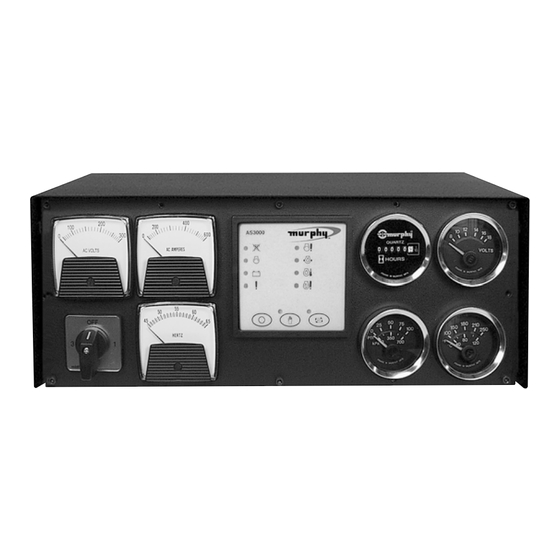
Description
The compact and powerful MGC2000 generator control system features a
unique, simple-to-install and setup design and enhanced operation.
The control method for the MGC2000 may be specified for using either the
AS3000 Autostart automatic controller or the 518APH electrically tripped
annunciator method.
The system is available in 2 basic configurations:
1. MGC2000 features mechanical gages:
- MGC2000-A
Automatic Control: with AS3000 Generator Controller.
- MGC2000-M
Manual Control: with 518APH annunciator control.
Both configurations include standard AC voltmeter, AC ammeter, and
frequency meter. Available for single phase, standard three phase, and three
phase re-configutable generators.
2. MGC2000E features electric gages:
- MGC2000E-A
Automatic Control: with AS3000 Generator Controller.
- MGC2000E-M
Manual Control: with 518APH annunciator control.
Both configurations include standard AC voltmeter, AC ammeter, and
frequency meter. Available for single phase, standard three phase, and three
phase re-configutable generators.
System Specifications
Pressure gage: 100°psi (680 kPa) [7 bar]
Mechanical gage pressure connection: 1/8" NPT.
Electric gage pressure connection: 2-wire.
Temperature gage: 0-250°F (121°C)
Mechanical gage temperature connection: 12ft. (3.67 m) capillary tubing
and sensing bulb.
Electric gage temperature connection: 2-wire.
Enclosure: 16 Ga CRS powder coated.
®
MGC2000
GENERAL INFORMATION
Optional NEMA 4X Type Enclosure:
Water and dust tight indoor/outdoor enclosure intended to protect
enclosed equipment against splashing, seepage, falling or hose-directed
water and severe external condensation.
AC Meters: AC ammeter and an AC voltmeter and a frequency meter are
standard features. Ranges must be specified.
Single or Three phase: Specify.
Control Method: may be specified:
- AS3000 Autostart automatic controller or
- 518APH Annunciator control method.
NOTE:
DC Voltage: 12 or 24 volt DC voltage must be specified.
Power supply:
• Continuous voltage range: 8-35 VDC
• Brown out voltage < 5 VDC for 2 secs (recovery to 8V)
• Blackout voltage: 0V for 50mS (from 10V, recovery to 5V)
• Overvoltage withstand: 50 VDC for 5 seconds (to SAEJ1810 load dump
immunity
• Reverse voltage withstand: 100 VDC continuous
Current consumption (standby): 50mA
Current consumption (max): 500mA (plus output loads)
DC Inputs:
• Pressure, coolant temperature
• Closed to negative DC (±3V) on fault auxiliary and charger faults
• Remote start positive open from positive DC to start
• Remote start negative close to negative DC (±3V) to start DC (±3V) to
activate DC input protection ±50 VDC max.
MGC-02030N page 1 of 8
WARNING: Do not bundle AC and DC wiring together. It is required
to use separate conduit runs and keep apart by at least 2 inches.
Autostart method is highly recommended.
MGC-02030N
Effective 04-03
Section 75
00-02-0505
continued on next page
Advertisement
Table of Contents

Related Manuals for Murphy MGC2000

Summary of Contents for Murphy MGC2000
- Page 1 2 inches. unique, simple-to-install and setup design and enhanced operation. The control method for the MGC2000 may be specified for using either the Optional NEMA 4X Type Enclosure: AS3000 Autostart automatic controller or the 518APH electrically tripped Water and dust tight indoor/outdoor enclosure intended to protect annunciator method.
- Page 2 DIMENSIONS FOR ALL MODELS To mount the MGC2000 drill and tap the mounting suface, see Mounting Drill Pattern, below. Use the four CAUTION: mounting inserts, one on each corner of the bottom of the enclosure, to secure the unit to the mounting surface by tightening the clamps with a blade type screwdriver.
- Page 3 NEMA 4X ENCLOSURE DIMENSIONS To mount the MGC2000 drill and tap the mounting suface, see Mounting hole Pattern, below. Use the CAUTION: four mounting holes (see mounting details), one on each corner of the bottom of the enclosure, to secure the unit to the mounting surface by tightening the clamps with a blade type screwdriver.
-
Page 4: System Basic Information
(unconnected) to initiate an automatic start. In all standard capable of causing a catastrophic failure of the CT. MGC2000’s, this connection is made by default, and the user connects the automatic start contacts to the "ground to activate" position on the... - Page 5 MGC2000 Typical Wiring Turn the power source off before attempting to perform the wiring operation. Do not bundle AC WARNING: and DC wiring together. It is required to use separate conduit runs and keep apart by at least 2 inches...
- Page 6 MGC2000E Typical Wiring Turn the power source off before attempting to perform the wiring operation. Do not bundle AC WARNING: and DC wiring together. It is required to use separate conduit runs and keep apart by at least 2 inches MGC-02030N page 6 of 8...
-
Page 7: Controller Troubleshooting
MGC2000 enclosure. A "daisy chained" ground that is looped from c. There is a noise source on the speed input: battery to frame to starter to Ac alternator to ground rod to MGC2000 is i. For AC Speed driven units, this can take the form of ‘dirty’... -
Page 8: Accessories And Replacement Parts
HOW TO ORDER THE MGC2000 MGC2000 1 – A – 12 – 300 – 600D – AMVMRLKS4XMP Base Model Options MGC2000 = Mechanical Gages AM = DC Ammeter MGC2000E = Electric Gages VM = DC Voltmeter HM = Hourmeter RL = Relays...
Need help?
Do you have a question about the MGC2000 and is the answer not in the manual?
Questions and answers