
Related Manuals for Sony ICF-403L


Summary of Contents for Sony ICF-403L
-
Page 1: Service Manual
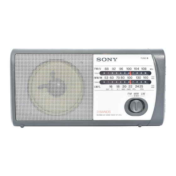
ICF-403L SERVICE MANUAL AEP Model Ver 1.0 1999.07 SPECIFICATIONS East European model AEP model FM/MW/LW 3 BAND RADIO MICROFILM... -
Page 2: Table Of Contents
TABLE OF CONTENTS Flexible Circuit Board Repairing • Keep the temperature of the soldering iron around 270°C during repairing. Specifications ................1 • Do not touch the soldering iron on the same conductor of the circuit board (within 3 times). 1. -
Page 3: Disassembly
SECTION 2 DISASSEMBLY The equipment can be removed using the following procedure. Cabinet (Rear) Cabinet (Front) Main board, Chassis Note : Follow the disassembly procedure in the numerical order given. 2-1. CABINET (REAR) 1 Screws +BTP 3x12 1 Screws +BTP 3x12 Cabinet (rear) Lug, 3 4 Screw... -
Page 4: Main Board, Chassis
2-3. MAIN BOARD, CHASSIS Chassis 2 Claws 4 Knob(tune) Main board 1 Screw +P 2.6x8 – 4 –... -
Page 5: Dial Pointer Installation
SECTION 3 SECTION 4 DIAL POINTER INSTALLATION ELECTRICAL ADJUSTMENTS Note : Follow the installation procedure in the numerical order given. TUNER SECTION • Repeat the procedures in each adjustment several times, and the frequency coverage and tracking adjustments should be finally done by the trimmer capacitors. -
Page 6: Diagrams
ICF-403L SECTION 5 DIAGRAMS 5-1. PRINTED WIRING BOARDS ANT1 FM TELESCOPIC ANTENNA MW/LW FERRITE-ROD ANTENNA [MAIN BOARD] TUNE EE MODEL C43 : EE MODEL CV1-4 JC1 : AEP MODEL EE MODEL TUNING BPF1 CV1 CV2 D2 D1 JW16 – SPEAKER EE MODEL DC IN 4.5V... -
Page 7: Schematic Diagram
ICF-403L 5-2. SCHEMATIC DIAGRAM Note: • All capacitors are in µF unless otherwise noted. pF: µµF • Power voltage is dc 4.5V and fed with regulated dc power • Voltages are taken with a VOM (Input impedance 10 MΩ). 50 WV or less are not indicated except for electrolytics supply from battery terminal (J2). -
Page 8: Exploded Views
SECTION 6 EXPLODED VIEWS NOTE : 6-2. CHASSIS SECTION • -XX, -X mean standardized parts, so they • The mechanical parts with no reference may have some difference from the original number in the exploded views are not one. supplied. •... -
Page 9: Electrical Parts List
SECTION 7 MAIN ELECTRICAL PARTS LIST NOTE : • Due to standardization, replacements in the • SEMICONDUCTORS When indicating parts by reference num- In each case, u : µ , for example : parts list may be different from the parts ber, please include the board. - Page 10 ICF-403L MAIN Ref. No. Part No. Description Remark Ref. No. Part No. Description Remark < JACK > MISCELLANEOUS *************** 1-770-666-11 JACK (@) 1-580-681-21 JACK,DC(POLARITY UNIFIED TYPE) * 52 1-674-032-21 RACK RETAINER BOARD (DC IN 4.5V) ANT1 1-501-222-81 ANTENNA, TELESCOPIC (FM) 8-719-069-94 LED TLR124 (TUNE) <...
Need help?
Do you have a question about the ICF-403L and is the answer not in the manual?
Questions and answers