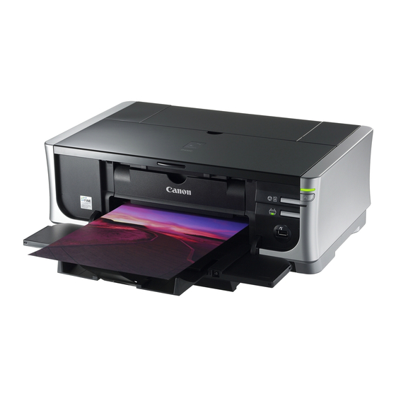
Canon iP4500 Simplified Service Manual
Hide thumbs
Also See for iP4500:
- Quick start manual (102 pages) ,
- Easy setup instructions (2 pages) ,
- Supplementary manual (6 pages)

Related Manuals for Canon iP4500


Summary of Contents for Canon iP4500
- Page 1 SIMPLIFIED SERVICE MANUAL 1. PRODUCT LIST 2. PRODUCT SPECIFICATIONS 3. ERROR DISPLAY 4. REPAIR 5. SERVICE MODE 6. SERVICE POLICY QY8-13BI-000 Rev. 00 July 12, 2007 Canon Inc.
- Page 2 1. PRODUCT LIST 1-1. Main Units Production q'ty Product name Product code Destination Accessories (for 3 months) Print head Canon Inkjet Printer Q30-4400-000 2171B001AA 180,000 Ink tanks iP4500 Q30-4401-000 2171B002AA 39,000 (Japan / Q30-4400-000 2171B003AA Non-Japan) BCI-9BK / PGI-5BK 2171B004AA...
- Page 3 *2: When printing equivalent to the 7.1megapixel image taken by certain Canon digital camera from PictBridge with “Default” settings on Print Effect without border using Photo Paper Plus Glossy.
- Page 4 Paper Same as the Rear tray, except that the Legal and Credit Card sizes and Photo Stickers specifications cannot be used in the cassette. DVD / CD print * Not supported in the US and KR models Supported media CD / DVD printable media Media size 120 mm / 80 mm Print operation...
- Page 5 CLI- CLI- CLI- CLI- Model Destination 7eBK iP4500 Japan Others Usable Not usable Note: The ink tanks for the Japanese model are not compatible with those for the other models. Be sure to use the appropriate ink tanks in servicing.
- Page 6 3. ERROR DISPLAY Errors are displayed by the LEDs, and ink low warnings are displayed by the Status Monitor. 3-1. Operator Call Error (Alarm LED Blinking in Orange) Alarm LED Error Corrective action Remarks blinking 2 times No paper in the rear tray. Set the paper in the rear tray, and press [1000] the Resume/Cancel button.
- Page 7 6 times Inner cover open before start Close the inner cover, and press the of printing on paper. [1841] Resume/Cancel button. (At CD-R is not (At CD-R is not supported.) supported.) Inner cover open during Close the inner cover, and press the printing on paper.
- Page 8 11 times Failed in automatic print Press the Resume/Cancel button. The error will occur (a) when head alignment. [2500] - If paper is being fed at error occurrence, the print head alignment the error is indicated after the paper is pattern is not printed due to ejected.
- Page 9 3-2. Service Call Error (by Cyclic Blinking in Orange (Alarm LED) and Green (Power LED), or Alarm LED Lit in Orange) Cycles of blinking in Error Corrective Action orange and green 2 times Carriage error [5100] - Carriage unit (QM3-2264) - Timing slit strip film (QC1-6526) - Logic board ass'y (QM3-2738) - Carriage motor (QK1-1500)
- Page 10 3-3. Warnings (1) Printer (No LED indication) Displayed warning Remarks Ink low Status indication only. Print head temperature rise If the print head temperature is high when the top cover is opened, the warning is displayed When the print head temperature falls, the warning is released.
- Page 11 4. REPAIR 4-1. Notes on Service Part Replacement (and Disassembling / Reassembling) Service part Notes on replacement Adjustment / settings Operation check Logic board ass'y - Before removal of the logic After replacement: - EEPROM QM3-2738 board ass'y, remove the 1.
- Page 12 PR lift shaft ass'y At replacement: - Service test print QL2-1450 Apply grease to the sliding portions. See 4-2. Grease Application Input carriage lift gear QC2-1873 Timing slit strip film - Wipe off any grease from After replacement: - Service test print QC1-6526 the film with ethanol.
- Page 13 4-2. Grease Application (1) Printer Unit Number of Drawing Grease / oil Part name Where to apply grease / oil Grease / oil drops* x amount (mg) locations Entire surface the carriage slider 1 Chassis ass'y Floil KG107A 27 to 54 3 x 1 contacts Carriage shaft cam L sliding...
- Page 15 4-3. Adjustment / Settings (1) Paper feed motor adjustment Perform the following adjustments when the paper feed motor unit is replaced: When attaching the motor, fasten the screws so that the belt is properly stretched (in the direction indicated by the blue arrow in the figure below). After replacement, be sure to perform the service test print, and confirm that no strange noise or faulty print operation (due to dislocation of the belt or gear, or out-of-phase motor, etc.) occurs.
- Page 16 5. SERVICE MODE Function Procedures Remarks Service test print See “Service mode Set a sheet of A4 or Letter size paper - Model name operation procedures” in the rear tray (cassette not usable). - Destination below. - ROM version - USB serial number - Ink absorber counter value (ink amount in the ink absorber) - LF / Eject correction value...
- Page 17 time(s) according to the function listed in the table below. (Each time the Resume/Cancel button is pressed, the Alarm and Power LEDs light alternately, Alarm in orange and Power in green, starting with Alarm LED.) Time(s) LED indication Function Remarks 0 times Green (Power) Power off...
- Page 18 6 times Green (Power) Asia Supported 7 times Orange (Alarm) China Supported 8 times Green (Power) Taiwan Supported 9 times Orange (Alarm) Supported 10 times Green (Power) Brazil Not released 11 times Orange (Alarm) Canada Supported 12 times or more Green (Power) Return to the menu selection Supported Note: After setting the destination, confirm the model name and destination in service test print or...
- Page 19 3 times HP BrightWhite 4 times Canon Extra, STEINBEIS Note: - Each time the Resume/Cancel button is pressed, the Alarm and Power LEDs light alternately, Alarm in orange and Power in green. - If the Resume/Cancel button is NOT pressed, and only the Power button is pressed, the printer remains in the LF / Eject correction mode.
- Page 20 In the printout, select the Pattern No. in which streaks or lines are the least noticeable, press the Resume/Cancel button the same number of time(s) as the selected Pattern No., then press the Power button.
- Page 21 3-1) LF correction value Selected pattern number Number of times the Resume/Cancel button is pressed (M) 1 (A) 1 time 0 (B) 0 times 2 (C) 2 times Note: - Each time the Resume/Cancel button is pressed, the Alarm and Power LEDs light alternately, Alarm in orange and Power in green.
- Page 22 L = 1 HR-101 GF-500 / Office L = 2 Planner L = 3 HP Bright White Canon Extra, L = 4 STEINBEIS 1 sheet of paper is printed. No(L>=5) - LF correction pattern on the left LF / Eject correction...
- Page 23 <Left margin correction> Adjust the left margin for duplex printing or printing from the cassette. 1) Duplex printing from the rear tray and cassette In the left margin correction mode, press the Resume/Cancel button 1 time, then press the Power button 1 time.
- Page 24 2 times +2 pitches 3 times +3 pitches 4 times -1 pitch 5 times -2 pitches 6 times -3 pitches Return to the service mode menu selection (no 7 times or more writing to the EEPROM) After the value is set, the machine returns to the parameter mode selection. Repeat steps 2) and 3) to adjust the left margin in each parameter mode: "back side of paper fed from the rear tray,"...
- Page 25 Left margin correction START Press the Resume/Cancel button "L" Start of duplex printing from the times, then press the Power button to rear tray and cassette (key entry) fix the selection. L = 0 No (N >=2) L = 1 Printing is performed according to Duplex printing from the the current correction values in...
- Page 26 Duplex printing from the rear tray and cassette START Paper source: Rear tray Paper type: Plain paper Print quality: Standard (Custom 3) Single-sided printing Print data: No data (blank) Print quantity: 1 sheet (1 page) Paper source: Rear tray Paper type: Plain paper Print quality: Standard (Custom 3)
- Page 27 Stock Date SENSO Parts, Starter Parts: From August 15, 2007 Other parts: From November 15, 2007 Repair by Canon Inc. Not available. (No repair is conducted by Canon Inc.) Parts for Available Parts <CMJ, CUSA> All parts Refurbishment <Others> Parts specified in the Parts Catalog...
- Page 28 This page intentionally left blank...
- Page 29 FIGURE 1 PRINTER & PRINT HEAD...
- Page 30 LIST OF FIGURE1 FIGURE PART & DESCRIPTION REMARKS NUMBER KEY No. QM3-2720-00 CASSETTE UNIT QC2-1925-000 COVER, CASSETTE QA4-1117-000 TRAY, CD SUB W/ CDR PRINTING QL2-1449-000 CDR TRAY ASS'Y W/ CDR PRINTING QY6-0067-000 PRINT HEAD 220V-240V(EUM, EMB, ASA, QH2-2716-000 CORD, POWER QH2-2719-000 CORD, POWER 100V-120V...
- Page 31 FIGURE 2 AC ADAPTER...
- Page 32 LIST OF FIGURE2 FIGURE & PART DESCRIPTION REMARKS KEY No. NUMBER QK1-3691-000 AC ADAPTER: 100V-240V 50/60HZ...
- Page 33 FIGURE 3 OPERATION PANEL UNIT & MAIN CASE UNIT...
- Page 34 LIST OF FIGURE3 FIGURE & PART DESCRIPTION REMARKS KEY No. NUMBER QM3-2193-000 PAPER SUPPORT UNIT QC1-9023-000 EMBLEM FOR JAPAN QC1-9024-000 EMBLEM FOR OTHER REGIONS QC2-4900-000 EMBLEM FOR FRANCE QM3-2190-000 ACCESS COVER UNIT QM3-2192-000 FRONT COVER UNIT QM3-2191-000 SIDE COVER R UNIT QC2-4418-000 COVER, LEFT QC2-4419-000...
- Page 35 FIGURE 4 BOTTOM CASE UNIT & INK ABSORBER...
- Page 36 LIST OF FIGURE4 FIGURE & PART DESCRIPTION REMARKS KEY No. NUMBER QY5-0190-000 ABSORBER KIT QM3-2718-000 BOTTOM CASE UNIT...
- Page 37 FIGURE 5 LOGIC BOARD ASS’Y...
- Page 38 LIST OF FIGURE5 FIGURE & PART DESCRIPTION REMARKS KEY No. NUMBER QM3-2738-000 LOGIC BOARD ASS'Y...
- Page 39 FIGURE 6 SHEET FEED UNIT...
- Page 40 LIST OF FIGURE6 FIGURE & PART DESCRIPTION REMARKS KEY No. NUMBER QM3-2746-000 DC CONNECTOR ASS'Y QM3-2749-000 MOTOR MULTI HARNESS ASS'Y ENCORDER MULTI HARNESS QM3-2740-000 ASS'Y QC2-5978-000 COVER, PAPER FEED GUIDE QM3-2723-000 SHEET FEEDER UNIT...
- Page 41 FIGURE 7 CARRIAGE UNIT...
- Page 42 LIST OF FIGURE7 FIGURE & PART DESCRIPTION REMARKS KEY No. NUMBER QC1-6526-000 FILM, TIMING SLIT STRIP QC1-6201-000 SPRING, LEAF QC2-0080-000 CLIP, SHAFT R QC2-4426-000 CAM, CARRIAGE SHAFT R QC2-0083-000 CLIP, SHAFT L QK1-1500-000 MOTOR, CARRIAGE QC2-4425-000 CAM, CARRIAGE SHAFT L QM3-2264-000 CARRIAGE UNIT QC2-0414-000...
- Page 43 FIGURE 8 PLATEN UNIT...
- Page 44 LIST OF FIGURE8 FIGURE & PART DESCRIPTION REMARKS KEY No. NUMBER QC2-4888-000 ABSORBER, INK QM3-2725-000 PLATEN UNIT QC1-6619-000 SPRING, TENSION QC2-4881-000 FILM, TIMING SLIT DISK EJECT...
- Page 45 FIGURE 9 PURGE UNIT...
- Page 46 LIST OF FIGURE9 FIGURE & PART DESCRIPTION REMARKS KEY No. NUMBER QK1-2830-000 CABLE, PANEL QM3-0007-010 PURGE UNIT QC2-0089-000 TUBE, INK QC2-0030-000 COVER, INK TUBE QC2-0085-000 TUBE, INK JOINT...
- Page 47 FIGURE 10 PAPER FEED & CARRIAGE LIFT PART...
- Page 48 LIST OF FIGURE10 FIGURE & PART DESCRIPTION REMARKS KEY No. NUMBER QC1-9941-000 CAM, SWING ARM LOCK QL2-1450-000 PR LIFT SHAFT ASS'Y QC1-6232-000 SPRING, TENSION QM2-3890-000 PAPER GUIDE UNIT QC1-9937-000 SPRING, TORSION QM2-3886-010 PRESSURE ROLLER ASS'Y QM3-1273-000 CARRIAGE LIFT SENSOR UNIT QC2-4433-000 CARRIAGE LIFT GEAR BASE UNIT QC2-1873-000...
- Page 49 FIGURE 11 OPTION & CONSUMABLES...
- Page 50 LIST OF FIGURE11 FIGURE & PART DESCRIPTION REMARKS KEY No. NUMBER 11 - BLACK INK TANK BCI-9BK CONSUMABLES BLACK INK TANK BCI-7eBK CONSUMABLES YELLOW INK TANK BCI7eY CONSUMABLES MAGENTA INK TANK BCI-7eM CONSUMABLES CYAN INK TANK BCI-7eC CONSUMABLES BLACK INK TANK PGI-5BK CONSUMABLES BLACK INK TANK CLI-8BK CONSUMABLES...
- Page 51 FIGURE 12 TOOL...
- Page 52 LIST OF TOOL FIGURE & PART DESCRIPTION REMARKS KEY No. NUMBER QY9-0057-000 LUBE, FLOIL KG107A, OIL...
- Page 53 SCREW & WASHER LIST FIGURE & PART DESCRIPTION REMARKS KEY No. NUMBER XB1-2300-405 SCREW, MACH.BH, M3X4 SCREW, TAP, WASHER HEAD, XA9-1752-000 M3X12 XB2-4300-605 SCREW, W/WASHER, M3X6 XB4-7300-805 SCREW, TP, BH3X8 XA9-1754-000 SCREW, BIND, M2.6X4(RED) XB1-2200-405 SCREW, M2X4...
-
Page 54: Numerical Index
NUMERICAL INDEX FIGURE FIGURE PART NUMBER PART NUMBER & DESCRIPTION & DESCRIPTION KEY No. KEY No. QA4-1117-000 3 TRAY, CD SUB QM3-0007-010 2 PURGE UNIT QC1-6201-000 2 SPRING, LEAF QM3-1273-000 10- 7 CARRIAGE LIFT SENSOR UNIT QC1-6202-000 11 SPRING, COIL QM3-1274-000 10- 15 PE SENSOR UNIT QC1-6212-000 10- 10 GEAR, IDLER CARRIAGE LIFT...
Need help?
Do you have a question about the iP4500 and is the answer not in the manual?
Questions and answers