Advertisement
MDR-RF430/RF450
SERVICE MANUAL
Ver 1.0
1998.06
MDR-RF430 is the component model block one in the MDR-RF430RK.
MDR-RF450 is the component model block one in the MDR-RF450RK.
COMPONENT MODEL NAME FOR MDR-RF430RK/RF450RK
MDR-RF430RK MDR-RF450RK
Wireless Headphones
MDR-RF430
Transmitter
TMR-RF450R
MICROFILM
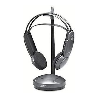
Illustration : MDR-RF430
MDR-RF450
TMR-RF450R
SPECIFICATIONS
Headphone
Charging and using hours
Approx. charging hours
Approx. using time*
1
50 minutes
24**
20 hours
*
at 1kHz 1mW + 1mW output
** the hours required to fully charge empty batteries
Battery life
Battery
Approx. hours*
Sony alkaline battery LR6 (SG) 60
Sony battery R6P (SR)
30
*
at 1kHz 1mW + 1mW output
Power source
DC 3V : 2 x R6 (size AA) battery or 2 x supplied
NC-AA-HJ Ni-Cd rechargeable battery
Mass
Approx. 215g (7.6oz.) incl.Ni-Cd batteries (MDR-RF430RK)
Approx. 265g (9.4oz.) incl.Ni-Cd batteries (MDR-RF450RK)
Supplied Ni-Cd rechargeable batteries
Model name
NC-AA-HJ
Voltage
1.2V
Capacity
600mAh
Design and specifications are subject to change without notice.
Illustration : MDR-RF450
WIRELESS STEREO HEADPHONES
AEP Model
Advertisement
Table of Contents


Need help?
Do you have a question about the MDR-RF450 and is the answer not in the manual?
Questions and answers