Aiwa NSX-AJ200 Service Manual
Hide thumbs
Also See for NSX-AJ200:
- Operating instructions manual (21 pages) ,
- Service manual (85 pages) ,
- Operating instructions manual (21 pages)
Advertisement
Table of Contents
- 1 Specifications
- 2 Protection of Eyes from Laser Beam During Servicing
- 3 Note on before Starting Repair
- 4 Electrical Main Parts List
- 5 Transistor Illustration
- 6 CD Test Mode
- 7 Mechanical Parts List
- 8 Color Name Table
- 9 Tape Mechanism Parts List
- 10 General Speaker Disassembly Instructions (for Reference)
- 11 Speaker Parts List
- 12 Accessories / Package List
- Download this manual
See also:
Service Manual
SERVICE MANUAL
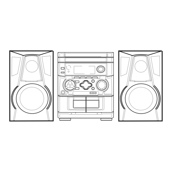
COMPACT DISC STEREO SYSTEM
SYSTEM
NSX–AJ200
(TYPE: U)
NSX–AJ205
(TYPE: U)
NSX–SZ200
(TYPE: EZ)
NSX–SZ205
(TYPE: EZ)
NSX–SZ200
(TYPE: LH)
• This Service Manual is the "Revision Publishing" and replace "Simple Manual"
NSX-AJ200/AJ205/SZ200/SZ205<U,EZ,LH>, (S/M Code No. 09-011-440-9T1).
• If requiring information about the CD mechanism, see Service Manual of
BZG-2 (S/M Code No. 09-00C-353-2N2).
NSX-AJ200
NSX-AJ205
NSX-SZ200
NSX-SZ205
BASIC CD MECHANISM : BZG-2 ZD4NC
BASIC TAPE MECHANISM: ZZM-3 YPR2NC
CD
SPEAKER
CASSEIVER
CX–NAJ200
SX–NAJ202
SX–NAJ205
CX–NAJ205
SX-R145
CX–NSZ200
SX–NSZ202
CX–NSZ205
SX–NSZ205
CX–NSZ200
SX–NSZ205
S/M Code No. 09-012-440-9R1
U
U
EZ,LH
EZ
REMOTE
CONTROLLER
RC–AAS11(VS)
Advertisement
Table of Contents

Related Manuals for Aiwa NSX-AJ200


Summary of Contents for Aiwa NSX-AJ200
- Page 1 CX–NSZ200 SX–NSZ205 (TYPE: LH) • This Service Manual is the “Revision Publishing” and replace “Simple Manual” NSX-AJ200/AJ205/SZ200/SZ205<U,EZ,LH>, (S/M Code No. 09-011-440-9T1). • If requiring information about the CD mechanism, see Service Manual of BZG-2 (S/M Code No. 09-00C-353-2N2). u163 S/M Code No. 09-012-440-9R1...
- Page 1 SX–NSZ205 (TYPE: LH) • This Service Manual is the “Revision Publishing” and replace “Simple Manual” NSX-AJ200/AJ205/SZ200/SZ205<U,EZ,LH>, (S/M Code No. 09-011-440-9T1). • If requiring information about the CD mechanism, see Service Manual of BZG-2 (S/M Code No. 09-00C-353-2N2). S/M Code No. 09-012-440-9R1...
-
Page 2: Specifications
SPECIFICATIONS 3 7 63 1515 0 TUNER FRONT SPEAKERS SX-NAJ202 ( only for NSX-AJ200) FM tuning range: 87.5 MHz to 108 MHz Speaker system: 2 way, bass reflex (magnetic shielded) FM usable Sensitivity(IHF): 13.2 dBf<U,LH>, 16.8 dBf<EZ> Speaker units: Woofer: 120 mm (4 in.) cone... -
Page 2: Specifications
SPECIFICATIONS TUNER FRONT SPEAKERS SX-NAJ202 ( only for NSX-AJ200) FM tuning range: 87.5 MHz to 108 MHz Speaker system: 2 way, bass reflex (magnetic shielded) FM usable Sensitivity(IHF): 13.2 dBf<U,LH>, 16.8 dBf<EZ> Speaker units: Woofer: 120 mm (4 in.) cone... -
Page 3: Protection Of Eyes From Laser Beam During Servicing
http://www.xiaoyu163.com PROTECTION OF EYES FROM LASER BEAM DURING SERVICING 3 7 63 1515 0 CAUTION This set employs laser. Therefore, be sure to follow carefully the instructions below when servicing. Use of controls or adjustments or performance of proce- dures other than those specified herin may result in WARNING!! hazardous radiation exposure. -
Page 3: Protection Of Eyes From Laser Beam During Servicing
PROTECTION OF EYES FROM LASER BEAM DURING SERVICING CAUTION This set employs laser. Therefore, be sure to follow carefully the instructions below when servicing. Use of controls or adjustments or performance of proce- dures other than those specified herin may result in WARNING!! hazardous radiation exposure. -
Page 4: Note On Before Starting Repair
http://www.xiaoyu163.com NOTE ON BEFORE STARTING REPAIR 1. Forced discharge of electrolytic capacitor of power supply block 3 7 63 1515 0 When repair is going to be attempted in the set that uses relay circuit in the power supply block, electric potential is kept charged across the electrolytic capacitors (C101, 102) even though AC power cord is removed. -
Page 4: Note On Before Starting Repair
NOTE ON BEFORE STARTING REPAIR 1. Forced discharge of electrolytic capacitor of power supply block When repair is going to be attempted in the set that uses relay circuit in the power supply block, electric potential is kept charged across the electrolytic capacitors (C101, 102) even though AC power cord is removed. - Page 5 http://www.xiaoyu163.com 3 7 63 1515 0 In such a case, check also if the POWER AMPLIFIER circuit or power supply circuit has any abnormalities or not. 2-2. Regarding reset There are cases that the machine does not work correctly because the MICROCOMPUTER is not reset even though the AC power cord is re-inserted, or the software reset (pressing the STOP key + POWER key) is performed.
- Page 5 In such a case, check also if the POWER AMPLIFIER circuit or power supply circuit has any abnormalities or not. 2-2. Regarding reset There are cases that the machine does not work correctly because the MICROCOMPUTER is not reset even though the AC power cord is re-inserted, or the software reset (pressing the STOP key + POWER key) is performed.
-
Page 6: Electrical Main Parts List
http://www.xiaoyu163.com ELECTRICAL MAIN PARTS LIST 3 7 63 1515 0 REF. NO. PART NO. KANRI DESCRIPTION REF. NO. PART NO. KANRI DESCRIPTION 87-A12-431-000 CAP,E 2200-50 M 85<200LH,205U> 87-A12-442-000 CAP,E 3300-25 M 85<EXCEPT 200U> 87-A21-269-010 IC,EW732 87-A12-440-000 CAP,E 3300-35 M 85 IV LELON<200U> 87-A21-893-040 C-IC,NJM4558V-TE2 87-A12-381-000... -
Page 6: Electrical Main Parts List
ELECTRICAL MAIN PARTS LIST REF. NO. PART NO. KANRI DESCRIPTION REF. NO. PART NO. KANRI DESCRIPTION 87-A12-431-000 CAP,E 2200-50 M 85<200LH,205U> 87-A12-442-000 CAP,E 3300-25 M 85<EXCEPT 200U> 87-A21-269-010 IC,EW732 87-A12-440-000 CAP,E 3300-35 M 85 IV LELON<200U> 87-A21-893-040 C-IC,NJM4558V-TE2 87-A12-381-000 CAP,E 2200-25 M 85<EXCEPT 200U> 87-A21-419-040 C-IC,NJM14558MD-TE2 87-A12-441-000... - Page 7 http://www.xiaoyu163.com 3 7 63 1515 0 REF. NO. PART NO. KANRI DESCRIPTION REF. NO. PART NO. KANRI DESCRIPTION C452 87-010-382-080 CAP, ELECT 22-25V C312 87-012-195-080 C-CAP,U 100P-50CH C453 87-012-279-080 C-CAP,U 2700P-50 B C501 87-010-759-080 C-CAP,U, 0.1-25F C454 87-012-279-080 C-CAP,U 2700P-50 B C502 87-010-759-080 C-CAP,U, 0.1-25F...
- Page 7 REF. NO. PART NO. KANRI DESCRIPTION REF. NO. PART NO. KANRI DESCRIPTION C452 87-010-382-080 CAP, ELECT 22-25V C312 87-012-195-080 C-CAP,U 100P-50CH C453 87-012-279-080 C-CAP,U 2700P-50 B C501 87-010-759-080 C-CAP,U, 0.1-25F C454 87-012-279-080 C-CAP,U 2700P-50 B C502 87-010-759-080 C-CAP,U, 0.1-25F C455 87-012-279-080 C-CAP,U 2700P-50 B C503...
- Page 8 http://www.xiaoyu163.com 3 7 63 1515 0 REF. NO. PART NO. KANRI DESCRIPTION REF. NO. PART NO. KANRI DESCRIPTION C788 87-012-167-080 C-CAP,U 5P-50 CH C942 87-012-165-080 CAP 3P<200EZ,205EZ> C789 87-A12-052-080 C-CAP,S 0.033-25<200LH,200U,205U> C947 87-012-286-080 CAP, U 0.01-25<200EZ,205EZ> C789 87-016-118-080 C-CAP,U0.022-25BJ<200EZ,205EZ> C948 87-A10-039-080 C-CAP,U 470P-50 J CH<200EZ,205EZ>...
- Page 8 REF. NO. PART NO. KANRI DESCRIPTION REF. NO. PART NO. KANRI DESCRIPTION C788 87-012-167-080 C-CAP,U 5P-50 CH C942 87-012-165-080 CAP 3P<200EZ,205EZ> C789 87-A12-052-080 C-CAP,S 0.033-25<200LH,200U,205U> C947 87-012-286-080 CAP, U 0.01-25<200EZ,205EZ> C789 87-016-118-080 C-CAP,U0.022-25BJ<200EZ,205EZ> C948 87-A10-039-080 C-CAP,U 470P-50 J CH<200EZ,205EZ> C790 87-A12-052-080 C-CAP,S 0.033-25<200LH,200U,205U>...
- Page 9 http://www.xiaoyu163.com 3 7 63 1515 0 REF. NO. PART NO. KANRI DESCRIPTION REF. NO. PART NO. KANRI DESCRIPTION C102 87-012-281-080 C-CAP,U 3900P-50 B<200EZ,205EZ,200U> C188 87-010-405-080 CAP, ELECT 10-50V<200LH,205U> C103 87-010-545-080 CAP, ELECT 0.22-50V CN101 87-A61-015-010 CONN,17P H BLK TAC-L17P-A3 C104 87-010-545-080 CAP, ELECT 0.22-50V R129...
- Page 9 REF. NO. PART NO. KANRI DESCRIPTION REF. NO. PART NO. KANRI DESCRIPTION C102 87-012-281-080 C-CAP,U 3900P-50 B<200EZ,205EZ,200U> C188 87-010-405-080 CAP, ELECT 10-50V<200LH,205U> C103 87-010-545-080 CAP, ELECT 0.22-50V CN101 87-A61-015-010 CONN,17P H BLK TAC-L17P-A3 C104 87-010-545-080 CAP, ELECT 0.22-50V R129 87-A00-257-080 RES,M/F 0.15-1W J<200LH,205U>...
-
Page 10: Transistor Illustration
http://www.xiaoyu163.com TRANSISTOR ILLUSTRATION 3 7 63 1515 0 E C B B C E B C E E C B 2SA1980G 2SA1981Y 2SB1342 CC5551 2SD1933 CDA1585BC 2SC5343G 2SB1370 2SD2619 CSC4115BC 2SB1677 2SD2642 KTC3198GR 2SB1686 G D S E C B 2SK2937 2SJ460 2SA1235F... -
Page 10: Transistor Illustration
TRANSISTOR ILLUSTRATION E C B B C E B C E E C B 2SA1980G 2SA1981Y 2SB1342 CC5551 2SD1933 CDA1585BC 2SC5343G 2SB1370 2SD2619 CSC4115BC 2SB1677 2SD2642 KTC3198GR 2SB1686 G D S E C B 2SK2937 2SJ460 2SA1235F CSD1306E 2SK360E 2SK2541 2SC2714O KRA102S 2SC3052F... - Page 11 http://www.xiaoyu163.com WIRING – 1 (MAIN / FRONT / TUNER)<EZ> 3 7 6 3 1 5 1 5 0 1 3 9 4 2 2 9 6 5 1 3 w w w u 1 6 3 – 11 – http://www.xiaoyu163.com...
- Page 11 WIRING – 1 (MAIN / FRONT / TUNER)<EZ> – 11 –...
- Page 12 http://www.xiaoyu163.com SCHEMATIC DIAGRAM – 1 (MAIN 1/2)<EZ> 3 7 6 3 1 5 1 5 0 1 3 9 4 2 2 9 6 5 1 3 w w w u 1 6 3 – 12 – http://www.xiaoyu163.com...
- Page 12 SCHEMATIC DIAGRAM – 1 (MAIN 1/2)<EZ> – 12 –...
- Page 13 http://www.xiaoyu163.com SCHEMATIC DIAGRAM – 2 (FRONT / DECK)<EZ> 3 7 6 3 1 5 1 5 0 1 3 9 4 2 2 9 6 5 1 3 w w w u 1 6 3 – 13 – http://www.xiaoyu163.com...
- Page 13 SCHEMATIC DIAGRAM – 2 (FRONT / DECK)<EZ> – 13 –...
- Page 14 http://www.xiaoyu163.com SCHEMATIC DIAGRAM – 3 (TUNER)<EZ> 3 7 6 3 1 5 1 5 0 1 3 9 4 2 2 9 6 5 1 3 w w w u 1 6 3 – 14 – http://www.xiaoyu163.com...
- Page 14 SCHEMATIC DIAGRAM – 3 (TUNER)<EZ> – 14 –...
- Page 15 http://www.xiaoyu163.com SCHEMATIC DIAGRAM – 4 (MAIN 2/2: PT SECTION)<EZ> 3 7 63 1515 0 L 13942296513 u163 – 15 – http://www.xiaoyu163.com...
- Page 15 SCHEMATIC DIAGRAM – 4 (MAIN 2/2: PT SECTION)<EZ> – 15 –...
- Page 16 http://www.xiaoyu163.com WIRING – 2 (MAIN / FRONT / TUNER)<U,LH> 3 7 6 3 1 5 1 5 0 1 3 9 4 2 2 9 6 5 1 3 w w w u 1 6 3 – 16 – http://www.xiaoyu163.com...
- Page 16 WIRING – 2 (MAIN / FRONT / TUNER)<U,LH> – 16 –...
- Page 17 http://www.xiaoyu163.com SCHEMATIC DIAGRAM – 5 (MAIN 1/2)<U,LH> 3 7 6 3 1 5 1 5 0 1 3 9 4 2 2 9 6 5 1 3 w w w u 1 6 3 – 17 – http://www.xiaoyu163.com...
- Page 17 SCHEMATIC DIAGRAM – 5 (MAIN 1/2)<U,LH> – 17 –...
- Page 18 http://www.xiaoyu163.com SCHEMATIC DIAGRAM – 6 (FRONT / DECK)<U,LH> 3 7 6 3 1 5 1 5 0 1 3 9 4 2 2 9 6 5 1 3 w w w u 1 6 3 – 18 – http://www.xiaoyu163.com...
- Page 18 SCHEMATIC DIAGRAM – 6 (FRONT / DECK)<U,LH> – 18 –...
- Page 19 http://www.xiaoyu163.com SCHEMATIC DIAGRAM – 7 (TUNER)<U,LH> 3 7 6 3 1 5 1 5 0 1 3 9 4 2 2 9 6 5 1 3 w w w u 1 6 3 – 19 – http://www.xiaoyu163.com...
- Page 19 SCHEMATIC DIAGRAM – 7 (TUNER)<U,LH> – 19 –...
- Page 20 http://www.xiaoyu163.com SCHEMATIC DIAGRAM – 8 (MAIN 2/2: PT SECTION)<200U> 3 7 63 1515 0 L 13942296513 u163 – 20 – http://www.xiaoyu163.com...
- Page 20 SCHEMATIC DIAGRAM – 8 (MAIN 2/2: PT SECTION)<200U> – 20 –...
- Page 21 http://www.xiaoyu163.com SCHEMATIC DIAGRAM – 9 (MAIN 2/2: PT SECTION)<205U> 3 7 63 1515 0 L 13942296513 u163 – 21 – http://www.xiaoyu163.com...
- Page 21 SCHEMATIC DIAGRAM – 9 (MAIN 2/2: PT SECTION)<205U> – 21 –...
- Page 22 http://www.xiaoyu163.com SCHEMATIC DIAGRAM - 10 (MAIN 2/2: PT SECTION)<200LH> 3 7 63 1515 0 L 13942296513 u163 – 22 – http://www.xiaoyu163.com...
- Page 22 SCHEMATIC DIAGRAM - 10 (MAIN 2/2: PT SECTION)<200LH> – 22 –...
- Page 23 http://www.xiaoyu163.com WIRING – 3 (AMP)<EZ> 3 7 6 3 1 5 1 5 0 1 3 9 4 2 2 9 6 5 1 3 w w w u 1 6 3 – 23 – http://www.xiaoyu163.com...
- Page 23 WIRING – 3 (AMP)<EZ> – 23 –...
- Page 24 http://www.xiaoyu163.com SCHEMATIC DIAGRAM – 11 (AMP)<EZ> 3 7 6 3 1 5 1 5 0 1 3 9 4 2 2 9 6 5 1 3 w w w u 1 6 3 – 24 – http://www.xiaoyu163.com...
- Page 24 SCHEMATIC DIAGRAM – 11 (AMP)<EZ> – 24 –...
- Page 25 http://www.xiaoyu163.com WIRING – 4 (AMP)<200U> 3 7 6 3 1 5 1 5 0 1 3 9 4 2 2 9 6 5 1 3 w w w u 1 6 3 – 25 – http://www.xiaoyu163.com...
- Page 25 WIRING – 4 (AMP)<200U> – 25 –...
- Page 26 http://www.xiaoyu163.com SCHEMATIC DIAGRAM – 12 (AMP)<200U> 3 7 6 3 1 5 1 5 0 1 3 9 4 2 2 9 6 5 1 3 w w w u 1 6 3 – 26 – http://www.xiaoyu163.com...
- Page 26 SCHEMATIC DIAGRAM – 12 (AMP)<200U> – 26 –...
- Page 27 http://www.xiaoyu163.com WIRING – 5 (AMP)<205U,200LH> 3 7 6 3 1 5 1 5 0 1 3 9 4 2 2 9 6 5 1 3 w w w u 1 6 3 – 27 – http://www.xiaoyu163.com...
- Page 27 WIRING – 5 (AMP)<205U,200LH> – 27 –...
- Page 28 http://www.xiaoyu163.com SCHEMATIC DIAGRAM – 13 (AMP)<200LH,205U> 3 7 6 3 1 5 1 5 0 1 3 9 4 2 2 9 6 5 1 3 w w w u 1 6 3 – 28 – http://www.xiaoyu163.com...
- Page 28 SCHEMATIC DIAGRAM – 13 (AMP)<200LH,205U> – 28 –...
- Page 29 http://www.xiaoyu163.com WIRING – 6 (DECK) 3 7 6 3 1 5 1 5 0 TO FRONT C.B CN504 E DECK C.B (FFC504) 1 3 5 7 9 11 2 4 6 8 10 (CAM2) (CAM1) (REA) (CST1) (CST2) SOL2 SOL1 SFR1 TAPE MOTOR...
- Page 29 WIRING – 6 (DECK) TO FRONT C.B CN504 E DECK C.B (FFC504) 1 3 5 7 9 11 2 4 6 8 10 (CAM2) (CAM1) (REA) (CST2) (CST1) SOL2 SOL1 SFR1 TAPE MOTOR – 29 –...
- Page 30 http://www.xiaoyu163.com IC BLOCK DIAGRAM 3 7 6 3 1 5 1 5 0 1 3 9 4 2 2 9 6 5 1 3 w w w u 1 6 3 – 30 – http://www.xiaoyu163.com...
- Page 30 IC BLOCK DIAGRAM – 30 –...
- Page 31 http://www.xiaoyu163.com FL (HNA-10SS19T) GRID ASSIGNMENT AND ANODE CONNECTION GRID ASSIGNMENT 3 7 63 1515 0 L 13942296513 u163 – 31 – http://www.xiaoyu163.com...
- Page 31 FL (HNA-10SS19T) GRID ASSIGNMENT AND ANODE CONNECTION GRID ASSIGNMENT – 31 –...
- Page 32 http://www.xiaoyu163.com ANODE CONNECTION / PIN CONNECTON 3 7 63 1515 0 L 13942296513 u163 – 32 – http://www.xiaoyu163.com...
- Page 32 ANODE CONNECTION / PIN CONNECTON – 32 –...
- Page 33 http://www.xiaoyu163.com IC DESCRIPTION IC, UPD780226GF-022-3BA<EXCEPT 205EZ> / UPD780228GF-079-3BA<205EZ> 3 7 63 1515 0 Pin No. Pin Name Description SOL1 DECK1 solenoid output. SOL2 DECK2 solenoid output. O-MOTOR DECK MOTOR ON/OFF output. O-PB2 DECK2/DECK1 play output. O-BIAS BIAS ON output. O-RMT REC mute output.
- Page 33 IC DESCRIPTION IC, UPD780226GF-022-3BA<EXCEPT 205EZ> / UPD780228GF-079-3BA<205EZ> Pin No. Pin Name Description SOL1 DECK1 solenoid output. SOL2 DECK2 solenoid output. O-MOTOR DECK MOTOR ON/OFF output. O-PB2 DECK2/DECK1 play output. O-BIAS BIAS ON output. O-RMT REC mute output. O-CD. ON CD ON output. O-TU.
- Page 34 http://www.xiaoyu163.com 3 7 63 1515 0 Pin No. Pin Name Description I-SPEANA2 A/D 2 input for spectrum analyser level display. I-SPEANA3 A/D 3 input for spectrum analyser level display. I-KEY1 Key 1 input. I-KEY2 Key 2 input. I-TU. SIG Tuner tuning signal level input (UPD780228GF-079-3BA only). AVSS GND.
- Page 34 Pin No. Pin Name Description I-SPEANA2 A/D 2 input for spectrum analyser level display. I-SPEANA3 A/D 3 input for spectrum analyser level display. I-KEY1 Key 1 input. I-KEY2 Key 2 input. I-TU. SIG Tuner tuning signal level input (UPD780228GF-079-3BA only). AVSS GND.
- Page 35 ADJUSTMENT – 1 <TUNER / FRONT> < TUNER SECTION > 1. Clock Frequency Check 11. FM Tracking adjust<U,LH> Settings : • Test point : TP2 (CLK) Settings : • Test point : TP8 (Lch), TP9 (Rch) Method : U,LH: Set to AM 1710 kHz and check that the test point •...
- Page 35 http://www.xiaoyu163.com ADJUSTMENT – 1 <TUNER / FRONT> < TUNER SECTION > 3 7 63 1515 0 1. Clock Frequency Check 11. FM Tracking adjust<U,LH> Settings : • Test point : TP2 (CLK) Settings : • Test point : TP8 (Lch), TP9 (Rch) Method : U,LH: Set to AM 1710 kHz and check that the test point •...
- Page 36 ADJUSTMENT – 2 <DECK> < DECK SECTION > 1. Tape Speed Adjustment (DECK 2) 4. REC/PB Frequency Response Check (DECK 2) Settings : • Test tape : TTA–100 Settings : • Test tape : TTA–602 • Test point : TP8 (Lch), TP9 (Rch) •...
- Page 36 http://www.xiaoyu163.com ADJUSTMENT – 2 <DECK> < DECK SECTION > 3 7 63 1515 0 1. Tape Speed Adjustment (DECK 2) 4. REC/PB Frequency Response Check (DECK 2) Settings : • Test tape : TTA–100 Settings : • Test tape : TTA–602 •...
-
Page 37: Cd Test Mode
CD TEST MODE 1. How to Start the CD Test Mode While pressing the FUNCTION button, insert the AC plug to the power outlet. When the test mode is started, the message [CD TEST] is displayed. 2. How to Exit the CD Test Mode Press the POWER button or disconnect the AC plug. -
Page 37: Cd Test Mode
http://www.xiaoyu163.com CD TEST MODE 3 7 63 1515 0 1. How to Start the CD Test Mode While pressing the FUNCTION button, insert the AC plug to the power outlet. When the test mode is started, the message [CD TEST] is displayed. 2. - Page 38 MECHANICAL EXPLODED VIEW 1 / 1 FFC602 BZG-2 FFC502 PT001 200U, 200EZ, 205EZ FFC504 HLDR, WIRE HT-SINK ZZM-3 HT-SINK, FIN 200LH, 205U CABI, BOTTOM CUSH, 11-8.5-2 – 38 –...
- Page 38 http://www.xiaoyu163.com MECHANICAL EXPLODED VIEW 1 / 1 3 7 6 3 1 5 1 5 0 FFC602 BZG-2 FFC502 1 3 9 4 2 2 9 6 5 1 3 PT001 200U, 200EZ, 205EZ FFC504 HLDR, WIRE HT-SINK ZZM-3 HT-SINK, FIN w w w 200LH, 205U CABI, BOTTOM...
-
Page 39: Mechanical Parts List
7 8B-NFA-008-010 WINDOW,DISP U<200U> 32 8B-NFA-058-010 CABI,REAR REZSC<205EZ> 8 8Z-NF6-210-010 DMPR,150 N 32 8B-NFA-051-010 CABI,REAR USC<200U> 9 87-B00-002-010 BADGE,AIWA 30 ABS SIL 33 8B-NFA-005-010 PANEL,LEFT 10 87-NF4-216-010 HLDR,LOCK 1 34 87-A80-157-010 AC CORD ASSY,E BLK CC<200EZ,205EZ> 11 86-NF9-224-010 SPR-C,LOCK 34 87-A80-092-010 AC CORD ASSY,E BLK SUN FAI<200LH>... -
Page 39: Mechanical Parts List
7 8B-NFA-008-010 WINDOW,DISP U<200U> 32 8B-NFA-058-010 CABI,REAR REZSC<205EZ> 8 8Z-NF6-210-010 DMPR,150 N 32 8B-NFA-051-010 CABI,REAR USC<200U> 9 87-B00-002-010 BADGE,AIWA 30 ABS SIL 33 8B-NFA-005-010 PANEL,LEFT 10 87-NF4-216-010 HLDR,LOCK 1 34 87-A80-157-010 AC CORD ASSY,E BLK CC<200EZ,205EZ> 11 86-NF9-224-010 SPR-C,LOCK 34 87-A80-092-010 AC CORD ASSY,E BLK SUN FAI<200LH>... - Page 40 TAPE MECHANISM EXPLODED VIEW 1 / 1 TERMINAL,LB1 TERMINAL, IC, EW732 IC, EW732 – 40 –...
- Page 40 http://www.xiaoyu163.com TAPE MECHANISM EXPLODED VIEW 1 / 1 3 7 6 3 1 5 1 5 0 TERMINAL, TERMINAL,LB1 IC, EW732 1 3 9 4 2 2 9 6 5 1 3 IC, EW732 w w w u 1 6 3 –...
-
Page 41: Tape Mechanism Parts List
TAPE MECHANISM PARTS LIST 1 / 1 REF. NO. PART NO. KANRI DESCRIPTION REF. NO. PART NO. KANRI DESCRIPTION 8Z-ZM3-227-010 BELT,MAIN M3 8Z-ZM3-233-010 SPR-T,BRG M3 8Z-ZM3-235-010 BELT,MAIN L 84-ZM2-227-310 SPR-C,AZIMUTH 8Z-ZM1-235-010 PULLEY,MOT 87-A90-403-110 HEAD,RPH MS15R 87-045-347-010 MOT,SHU2L 70 87-A90-404-010 HEAD,EH LE15B 8Z-ZM1-232-010 GEAR,IDL FF/REW 8Z-ZM3-239-010... -
Page 41: Tape Mechanism Parts List
http://www.xiaoyu163.com TAPE MECHANISM PARTS LIST 1 / 1 3 7 63 1515 0 REF. NO. PART NO. KANRI DESCRIPTION REF. NO. PART NO. KANRI DESCRIPTION 8Z-ZM3-227-010 BELT,MAIN M3 8Z-ZM3-233-010 SPR-T,BRG M3 8Z-ZM3-235-010 BELT,MAIN L 84-ZM2-227-310 SPR-C,AZIMUTH 8Z-ZM1-235-010 PULLEY,MOT 87-A90-403-110 HEAD,RPH MS15R 87-045-347-010 MOT,SHU2L 70 87-A90-404-010... -
Page 42: General Speaker Disassembly Instructions (For Reference)
GENERAL SPEAKER DISASSEMBLY INSTRUCTIONS (FOR REFERENCE) Type.1 Type.4 TOOLS Insert a flat-bladed screwdriver into the position indicated by the arrows and remove the panel. Remove the screws of each speaker 1 Plastic head hammer unit and then remove the speaker units. 2 (() flat head screwdriver 3 Cut chisel How to Remove the PANEL, FR... -
Page 42: General Speaker Disassembly Instructions (For Reference)
http://www.xiaoyu163.com GENERAL SPEAKER DISASSEMBLY INSTRUCTIONS (FOR REFERENCE) 3 7 63 1515 0 Type.1 Type.4 Insert a flat-bladed screwdriver into the position indicated by the TOOLS arrows and remove the panel. Remove the screws of each speaker 1 Plastic head hammer unit and then remove the speaker units. -
Page 43: Speaker Parts List
SPEAKER PARTS LIST (SX-NAJ202<YUSN> / NSZ202<YSC> / NSZ205<YSC, YLSC> / NAJ205<YUSN>) REF. NO. PART NO. KANRI DESCRIPTION REF. NO. PART NO. KANRI DESCRIPTION 1 8B-NSL-001-010 PANER,FR 2 8B-NSL-006-010 GRILLE,FRAME ASSY<NSZ205YLSC,SNAJ205YUSN> 2 8B-NSL-020-010 GRILLE,FRAME ASSY 2WAY<NSZ202YSC,SNAJ202YUSN,NSZ205YSC> 3 8A-NSL-603-010 SPKR, CERAMIC 4 8B-NSL-019-010 SPKR, CERAMIC ASSY 5 8B-NSL-602-010 SPKR, W 120/25<NSZ205YLSC,SNAJ205YUSN>... -
Page 43: Speaker Parts List
http://www.xiaoyu163.com SPEAKER PARTS LIST (SX-NAJ202<YUSN> / NSZ202<YSC> / NSZ205<YSC, YLSC> / NAJ205<YUSN>) 3 7 63 1515 0 REF. NO. PART NO. KANRI DESCRIPTION REF. NO. PART NO. KANRI DESCRIPTION 1 8B-NSL-001-010 PANER,FR 2 8B-NSL-006-010 GRILLE,FRAME ASSY<NSZ205YLSC,SNAJ205YUSN> 2 8B-NSL-020-010 GRILLE,FRAME ASSY 2WAY<NSZ202YSC,SNAJ202YUSN,NSZ205YSC> 3 8A-NSL-603-010 SPKR, CERAMIC 4 8B-NSL-019-010... - Page 44 2–11, IKENOHATA 1–CHOME, TAITO-KU, TOKYO 110, JAPAN TEL:03 (3827) 3111 9820572 0251431 Printed in Singapore...
- Page 44 http://www.xiaoyu163.com 3 7 63 1515 0 L 13942296513 u163 2–11, IKENOHATA 1–CHOME, TAITO-KU, TOKYO 110, JAPAN TEL:03 (3827) 3111 9820572 0251431 Printed in Singapore http://www.xiaoyu163.com...
Need help?
Do you have a question about the NSX-AJ200 and is the answer not in the manual?
Questions and answers