Table of Contents
Advertisement
Quick Links
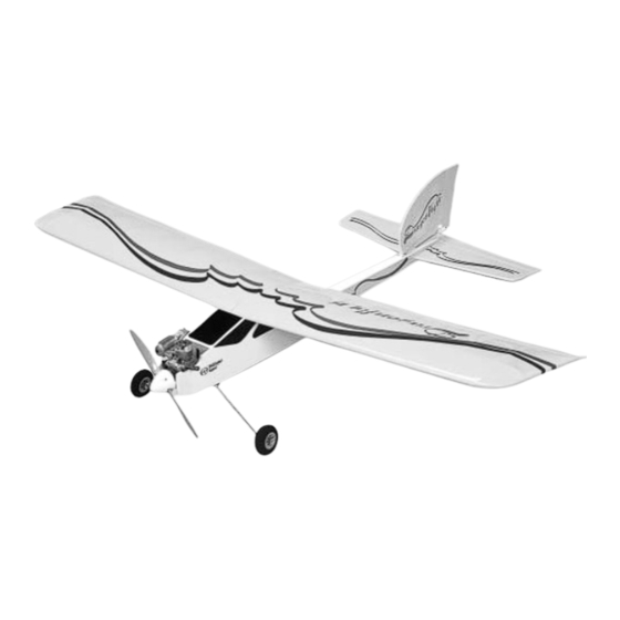
Item No. 4574
Thunder Tiger Model Company guarantees this model kit to be free from defects in both material and
workmanship at date of manufacture. This warranty does not cover any components damaged by use or
modification and in no case shall Thunder Tiger's liability exceed the original purchase price of the kit.
Thunder Tiger also reserves the right to change or modify this warranty without notice.
Since Thunder Tiger Model Co. has no control over possible shipping damages or construction tech-
niques and materials used for construction by the modeler, no liability can be assumed nor accepted for
damage resulting from the use by the user of the final user-assembled product. By the act of using this
user-assembled product, the user accepts all resulting liability. If the buyer is not prepared to accept this
liability, he should return this kit in new and unused condition to the place of purchase for a full refund.
Assembly Instructions
WARRANTY
Specifications:
Wing Span: 44"(1116mm)
Length:
35 1/4" (896mm)
Weight:
37~40 oz.(1050~1150g)
Engine:
.10~.15 req'd
Radio:
3~4 channel req'd
JE6640
Advertisement
Table of Contents

Related Manuals for THUNDER TIGER Dragonfly 15


Summary of Contents for THUNDER TIGER Dragonfly 15
- Page 1 3~4 channel req'd WARRANTY Thunder Tiger Model Company guarantees this model kit to be free from defects in both material and workmanship at date of manufacture. This warranty does not cover any components damaged by use or modification and in no case shall Thunder Tiger’s liability exceed the original purchase price of the kit.
-
Page 2: Table Of Contents
INTRODUCTION INTRODUCTION All of us at Thunder Tiger want to thank you for choosing the best looking, easiest building and best flying ARF trainer available the...Dragonfly 15. This kit features state-of-the-art engineering that provides quick and easy assembly of a strong, yet lightweight airplane that will give you an enjoyable and educational experience. -
Page 3: Items Need Check List
Stick on Lead Strip for balancing the plane 3 or 4 Props (see engine instructions) 10%-15% Glow Fuel Engine - The Thunder Tiger GP-15 is the ideal Fuel Pump or Bulb engine for this airplane. This quiet running engine is easy to start, requires no special Electric Starter or “Chicken Stick”... -
Page 4: Parts List
PARTS SKETCHES ORDER BY BAG NUMBER ONLY INDIVIDUAL PARTS NOT AVAILABLE AS6271 Main Wing Joiner(2) Nylon Torque Horn(2) Wing Protector(1) Left Wing(1) Right Wing(1) Aileron Servo Stand(2) CA Hinge(6) AS6272 Horizontal Tail AS6273 Vertical Tail No.3254 Wheel CA Hinge(4) CA Hinge(2) Horizontall Tail(1) Wheel(2) Vertical Tail(1) -
Page 5: Pre-Assembly Notes
PRE-ASSEMBLY PRE-ASSEMBLY NOTE 1.If you are not an experienced R/C pilot, plan to have a fully competent pilot check your complet- ed model and help you with your first flights. Even though we have tried to provide you with a very thorough instruction manual, R/C models are rather complicated and an experienced modeler can quickly check over your model to... -
Page 6: Tail Feathers
TAIL FEATHERS TAIL FEATHERS 4.Locate the plastic wing protector plate and light- ly sand the edges on one side of the plate by 80-grit sandpaper. Center the plate across the wing joint and flush with the trailing edge then glue with thick CA. 7.Use the same way as you did on aileron to glue the rudder and elevator on the tails. -
Page 7: Fuselage
FUSELAGE LANDING GEAR 90˚ 11.Locate the main landing gear and the three 9.Apply 5-Minute Epoxy or thick CA onto the hor- retainers. Place the landing gear and retainer izontal tail and vertical tail along the area where on the fuselage bottom as shown. Make marks the covering were removed. -
Page 8: Install The Engine
INSTALL THE ENGINE does, simply cut a small portion of the fuel tub- ing until the clunk no longer reaches the rear of the tank. 14.Locate the four pre-drilled wing dowel holes, two on either side of the fuselage. Using a sharp hobby knife, carefully cut the covering 16.Cut two 5”... -
Page 9: Control Horn
CONTROL HORNS 20.Locate the plastic pushrod tube through the 18.Using a Philips screwdriver, firmly secure the pre-drilled hole in the firewall of the fuselage engine by four 3x14mm machine screw, M3 until approximately 1/2"(1.5mm) of the tube spring washers, M3 washer and M3 nuts. protrudes from the firewall. -
Page 10: Control Horn
CONTROL HORNS 24.Attach the control horn using the hardware pro- vided ( 2x22mm screws, back plate, control 22.Insert the pushrod to the holes on former, the horn base and nylon horn) and fasten in place lower one is elevator pushrod and the other is using a Philips screwdriver. -
Page 11: Servo Installation
SERVO INSTALLATION 28.When everything is set, slip a short piece of fuel line over all clevises to prevent them from snapping open in flight. 26.Refer to manual of radio then install the rubber grommets and eyelets which come with your servos. - Page 12 SERVO INSTALLATION 33.Install the rubber servo grommets and eyelets in the aileron servo. Next, secure the aileron servo in place as illustrated. 31.The switch should be mounted on the left side of the fuselage, using a sharp hobby knife carefully cut the opening for the switch. Detach the switch plate from the receiver switch har- ness.
-
Page 13: Radio Adjustment
RADIO ADJUSTMENT ELEVATOR AILERONS 1/4” 1/2” UP 5/16” DOWN 1/2” DOWN RIGHT AILERON: Aileron on the right moves upward; aileron on the left moves downward. DOWN LEFT AILERON: Aileron on the left moves upward; aileron on the right moves downward. DOWN ELEVATOR UP ELEVATOR RUDDER/NOSE WHEEL... -
Page 14: Balance
BALANCE 3" (75mm) BALANCING YOUR PLANE PRE-FLIGHT If you are an experienced pilot, some of the IMPORTANT - Do not attempt to fly your model following text will not apply to you. Simply before completing this very important section. disregard references to “your first flights.” A model that is not properly balanced will be unsta- ble and could cause serious damage and/or injury. - Page 15 PRE-FLIGHT CHECKS right. Pretty simple right? Well, not quite. Since you If your radio uses dry cells, make sure your bat- are really standing on the ground and not sitting in teries are in new condition. You have a lot of money the plane, this is how the controls work when you are invested in this project so it is not worth the risk of facing the same direction the plane is flying.
-
Page 16: Post-Flight Check List
POST-FLIGHT CHECK LIST 6. Inspect the entire plane for covering tears, have an experienced pilot make the adjustments for new dings and dents, loose screws and you while you fly the plane. connectors and any other wear and tear. If you get disoriented or the plane gets out of con- 7.
Need help?
Do you have a question about the Dragonfly 15 and is the answer not in the manual?
Questions and answers