Advertisement
Quick Links
Download this manual
See also:
Owner's Manual
CUSTOMER: VESTAX
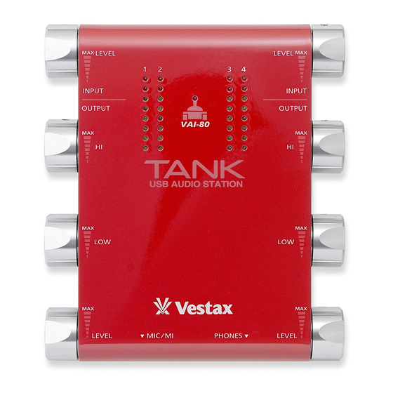
MODEL : VAI-80
FEATURES:-
The VAI-80 is a compact and stylish digital ausio interface capable of multi channel
playback and recording. Each input has GAIN & EQ (hi, low) control to enable
flexible adjustments for live recording. An excellent tool with high sound quality
for any DJ or DAW software.
SERVICE MANUAL
Advertisement

Subscribe to Our Youtube Channel
Related Manuals for Vestax VAI-80


Summary of Contents for Vestax VAI-80
- Page 1 MODEL : VAI-80 FEATURES:- The VAI-80 is a compact and stylish digital ausio interface capable of multi channel playback and recording. Each input has GAIN & EQ (hi, low) control to enable flexible adjustments for live recording. An excellent tool with high sound quality...
-
Page 2: Disassembly Procedures
DISASSEMBLY PROCEDURES Part No.: SCM0305HBBI (Hex Screw) * 8pcs Part No.: NMM2101101 (Aluminium Rotary Knob) *8pcs Part No.: - (Nut) * 8pcs Part No.: - (Washer) * 8pcs Part No.: MT5120203 (Side Bracket) *2pcs at Left and Right Side Part No.: SC0306PBBI (Screw) *4pcs at Left and Right Side Bracket 1~2 ) Take out Aluminium Rotary Knob * 8 pcs and Hex Screw * 8 pcs from the... - Page 3 DISASSEMBLY PROCEDURES Part No.: MT5120405 (Side Panel R ‘DC-IN’) *1pc Part No.: SC0306PBBI (Screw) *4pcs at Left and Right Side Panel Part No.: MT5120404 (Side Panel L ‘USB’) *1pc Part No.: MT5130004 (Aluminium Top Case) *2pcs Part No.: SC0306BIBI (Screw) *2pcs Part No.: SC0308PBBI (Screw) *4pcs 7~9 ) Remove screw * 4 pcs and then take out the Side Panel R (DC-IN) and...
- Page 4 DISASSEMBLY PROCEDURES Part No.: SC0306PBBI (Screw) *5pcs Part No.: MT5120403 (Jack Panel) Part No.: TWPCSNC1002 (LED PCB Ass'y) Part No.: TWPCSNC1001BA Connector Wire *6PCS (Volume PCB Ass'y) 13~14 ) Remove screw * 3 pcs from LED PCB Ass’y and screw * 2 pcs from Jack Panel.
- Page 5 DISASSEMBLY PROCEDURES Part No.: NMM2103201 (FELT RING) Part No.: MT5130303 (Metal Bottom Case) Part No.: TWPCSNC1001AA (Jack PCB Ass'y) Part No.: UHK5BRC10X20X5 (CLIP COIL) 18 ) Remove Jack PCB Ass’y from Metal Bottom Case.
- Page 6 RUBBER FOOT LOCATION Part No.: RUM2100501 (Rubber Foot) *4 pcs...
-
Page 7: Packing Diagram
PACKING DIAGRAM Part No.: SDM20526000 (Lamin Bag) Part No.: PUMSNC01 (PE Foam Cushion) Part No.: OPMVAISNC01 Part No.: PE1802555000 (Quick Start Manual) (Plastic Bag) Part No.: GE39TMV01 (Guarantee Card) Part No.: GE39TMV02 Part No.: BAMUSBCD01 (Customer Instruction Card) (USB CD) - Page 8 PACKING DIAGRAM Part No.: CA040218002 (USB CABLE (BLACK) + CORE Part No.: CGMVAI310SNC01 (Inner Carton) Part No.: CBM310SNC02 (Nesting) Part No.: CTMVAI510SNC01 (Outer Carton)
- Page 9 SCHEMATIC DIAGRAM JACK PCB (TUSB)
- Page 10 SCHEMATIC DIAGRAM JACK PCB (INPUT)
- Page 11 SCHEMATIC DIAGRAM JACK PCB (OUTPUT)
- Page 12 DISASSEMBLY PROCEDURES VOLUME PCB (POWER)
- Page 13 DISASSEMBLY PROCEDURES VOLUME PCB (EQ)
- Page 14 DISASSEMBLY PROCEDURES VOLUME PCB (SELECT)
- Page 15 DISASSEMBLY PROCEDURES LED PCB...
Need help?
Do you have a question about the VAI-80 and is the answer not in the manual?
Questions and answers