Table of Contents

Related Manuals for LG 21CD1RGE


Summary of Contents for LG 21CD1RGE
-
Page 1: Service Manual
COLOR TV SERVICE MANUAL CHASSIS : MC-049B MODEL : 20/21CD1RGE 20/21CD1RGE-TB CAUTION BEFORE SERVICING THE CHASSIS, READ THE SAFETY PRECAUTIONS IN THIS MANUAL. -
Page 2: Table Of Contents
CONTENTS Contents ........................2 Safety Precautions....................3 Control Descriptions..................4 Specifications......................7 Adjustment Instructions .................8 T rouble Shooting....................12 Printed circuit board..................16 Block Diagram ......................19 Exploded View....................20 Exploded View Parts List ................21 Replacement Parts List .................22 SVC. Sheet........................- 2 -... -
Page 3: Safety Precautions
SAFETY PRECAUTIONS IMPORT ANT SAFETY NOTICE Many electrical and mechanical parts in this chassis have special safety-related characteristics. These parts are identified by the Schematic Diagram and Replacement Parts List. It is essential that these special safety parts should be replaced with the same components as recommended in this manual to prevent X-RADIATION, Shock, Fire, or other Hazards. -
Page 4: Control Descriptions
DESCRIPTION OF CONTROLS All the functions can be controlled with the remote control handset. Some functions can also be adjusted with the buttons on the front panel of the set. POWER MUTE Remote control handset Before you use the remote control handset, please install the bat- teries. -
Page 5: Selects A Programme For The Sub Picture
º / ) (option) MENU/INDEX TV/AV selects surround sound. 18. VCR BUTTONS control a LG video cassette recorder. 19. PIP BUTTONS (option) switches the sub picture on or off. PR +/- selects a programme for the sub picture. SWAP alternates between main and sub picture. -
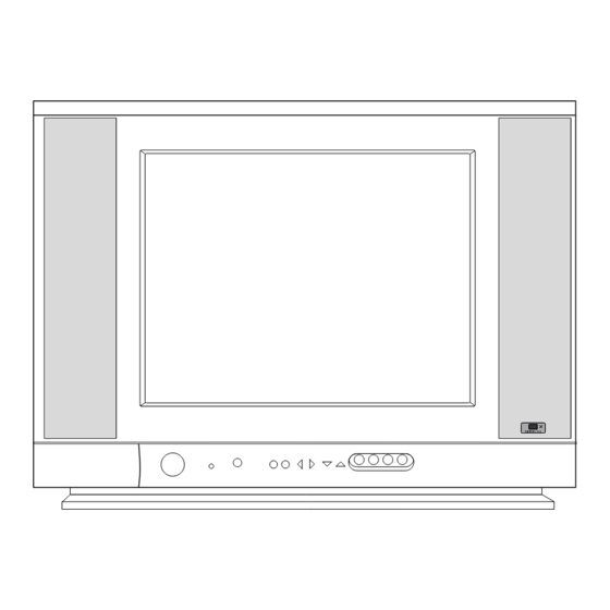
Page 6: Input
Front panel Shown is a simplified representation of front or side panel. Here shown may be somewhat different from your set. VIDEO VIDEO ON/OFF MENU OK VIDEO (L/MONO)-AUDIO-(R) P-TURBO-S (L/MONO) AUDIO AUDIO 2 3 4 ON/OFF MENU OK VIDEO (L/MONO)-AUDIO-(R) S-TURBO-P VIDEO VIDEO... -
Page 7: Specifications
1) Temperature : 20 ± 5 ° C Test and Inspection Method (CST must be tested 40 ± 5°C . Humidity : 50%) 1) Capacity : Follow LG electronics TV testing Standard. 2) Relative Humidity : 65 ± 10% 2) Another Required Standard... -
Page 8: Adjustment Instructions
2 tabs of the 6pole (8) Signal : Receive the standard color signal (65dB±1dB uV) magnet. LG standard signal means the digital pattern,EU 4) Converge the R,G,B horizontal line in the same line by 05 CH(PAL) turning the 2 tabs of the 6pole magnet. -
Page 9: Position
2) Enter the white balance adjust mode with a factory 6. SUB Brightness adjustment remote control. Receiving signal : Digital pattern (PAL : EU05CH) 3) Adjust HIGh Light status of WDR R, WDR B at WDR G. 1) In the LINE SVC MODE(IN-START key), select 4) Make the Picture luminance 4.5±1 Ft-L by changing the SERVICE11 change S-BRI by VOL ±... - Page 10 2) Mark the option adjustment data like [104,137,162,117,148] Adjust until the distance between PIP and main picture in BOM. becomes about 1~2mm. Mark of BOM <Table 4> Deflection initial data - 21” LG Flat CPT(TINT GLASS) LEVEL PART NO. SPECIFICATION DESCRIPTION JOP EXP.
- Page 11 <OPTION3> <OPTION5> Option Code Function Option Code Function Without TEXT (200PR) LNA Disable TEXT With TEXT (100PR) LNA Enable FLOP A2_ST A2_ST Disable (MONO, AV-STEREO) A2_ST Enable (RF-STEREO) Without ACMS BASIC version micom (RF0STEREO model) ACMS With ACMS ECO version micom (AV-STEREO) model) Without DUAL SOUND SAVE TILT TILT function disable...
-
Page 12: Trouble Shooting
TROUBLE SHOOTING RF- STEREO MODEL PICTURE O. K / NO SOUND Selec t ed c o rrec t syst em In m enu Chec k t he wavef o rm Chec k / Rep lac e IF 1 o f TU101 TU 101 Chec k t he wavef o rm Chec k The Vo lt ag e... - Page 13 No Ras ter ( 2/ 2) CHECK B+ At D829 c at ho d e No rm al Ab no rm al Op en Is t he vo lt ag e a t Chec k eac h p in vo lag e o f IC11 Fuse o f AC line Chec k / Rep lac e Chec k t he...
- Page 14 NO Pic t ure No So und Is Any OSD d isp la yed ? Chec k IC11 p in71, 7 2, 73 Chec k rec eiving syst em in MENU & exec ut e Aut o Pro g ram . ( R, G, B o ut ) Do es t he auto Pro g ra m Op erat e p ro p erly...
- Page 15 AV STERRO / MONO MODEL Selec t c o rrec t syst em In m enu Chec k t he c o nnec t io n Of AV eq uip m ent Chec k t he wavef o rm At p in16, 17 o f IC11 Chec k TU1 01 Tuner Chec k t he vo lt ag e Chec k t he wavef o rm...
-
Page 16: Printed Circuit Board
PRINTED CIRCUIT BOARD MAIN - 16 -... - Page 17 COMPONENT LOCATION GUIDE C10 ..C4 C403 ..G3 C541 ..C3 C823..E1 D827 ..D2 P803A..F1 R36 ..C2 R410..F4 R605..A4 R904..B1 C11 ..C4 C404..F3 C542..B5 C824 ..D1 D828 ..D2 P803B..F1 R37 ..D1 R412 ..D4 R606..A4 R905..B1 C12 ..C4 C405 ..G3 C543 ..C5 C825 ..D2 D829 ..D3 P902A ..C2 R38..B4...
- Page 18 MEMO - 18 -...
-
Page 19: Block Diagram
BLOCK DIAGRAM VIDEO/AUDIO RESET DATA/CLOCK ON / OFF Y/Cb/Cr-IN SCART RGB-IN AV-IN TV / MONITOR OUT PIP-VIDEO PIP-RGB - 19 -... -
Page 20: Exploded View
EXPLODED VIEW P801 - 20 -... -
Page 21: Exploded View Parts List
BUTTON, POWER RT-20CD10 ABS 1KEY LGEEG 3809V00596B 3809V00596B BACK COVER ASSEMBLY, 1PHONE SY-LGEEG(EG TOOL) 6871VMM939X 6871VMM939Y PWB(PCB) ASSEMBLY,MAIN M.I MC049B NFULLDE SY-CKD 0IGL120104A 0IGL120104A IC,LG SEMICONDUCTOR CDS SENSOR MODULE(P1201-04) 332-057B 332-057B SCREW,DRAWING ASSY,HEXAGON HEAD 1PTF0403116 1PTF0403116 SCREW TAP TITE(P), + D4.0 L16.0 MSWR3/FZB P801 6410VEH001B... -
Page 22: Replacement Parts List
REPLACEMENT PARTS LIST For Capacitor & Resistors, the CC, CX, CK, CN : Ceramic RD : Carbon Film charactors at 2nd and 3rd digit CQ : Polyestor RS : Metal Oxide Film in the P/No. means as follows; CE : Electrolytic RN : Metal Film RF : Fusible LOCA. - Page 23 For Capacitor & Resistors, CC, CX, CK, CN : Ceramic RD : Carbon Film the charactors at 2nd and 3rd CQ : Polyestor RS : Metal Oxide Film digit in the P/No. means as CE : Electrolytic RN : Metal Film follows;...
- Page 24 For Capacitor & Resistors, CC, CX, CK, CN : Ceramic RD : Carbon Film the charactors at 2nd and 3rd CQ : Polyestor RS : Metal Oxide Film digit in the P/No. means as CE : Electrolytic RN : Metal Film follows;...
- Page 25 For Capacitor & Resistors, CC, CX, CK, CN : Ceramic RD : Carbon Film the charactors at 2nd and 3rd CQ : Polyestor RS : Metal Oxide Film digit in the P/No. means as CE : Electrolytic RN : Metal Film follows;...
- Page 26 366-043K WAFER, PLUG(4P) P801 366-043B WAFER, ASSY,PLUG(2P) P802 366-043B WAFER, ASSY,PLUG(2P) ACCESSORIES 3828VA0475F MANUAL, NEU LG AR/EN 124E TX 6710V00124D REMOTE CONTROLLER, MC049B W/O TXT 5010V00004B ANTENNA, 3SECTION 750MM NTSC W/ADP MISCELLANEOUS F801 0FS4001B53C FUSE, 4000MA 250 V 5.2X20 JK202...
- Page 28 Aug., 2005 P/NO : 38289S0006B Printed in Korea...
Need help?
Do you have a question about the 21CD1RGE and is the answer not in the manual?
Questions and answers