Table of Contents
Advertisement
Quick Links
Advertisement
Table of Contents

Related Manuals for Kyosho Syncro EX-6


Summary of Contents for Kyosho Syncro EX-6
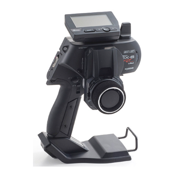
- Page 1 Before beginning assembly, please read these instructions thoroughly. DIGITAL PROPORTIONAL SYSTEM DIGITAL PROPORTIONAL SYSTEM Instruction Manual *Specifications are subject to be changed without prior notice! THE FINEST RADIO CONTROL MODELS © Copyright 2015 KYOSHO CORPORATION / 禁無断転載複製 82030-T01...
-
Page 2: Table Of Contents
■ Table of Contents Title Title Page Page ■ Table of Contents ▶VR INFORMATION Volume information ■ For Safe Operation ▶KEYSPEED ■ Getting Started ▶OPERATIN ALARM ●Transmitter Assembly □■□STEERING MENU ●Transmitter Dismantling ●TRAVEL MENU ■ Names of Parts ▶ST TRAVEL Steering Travel ●ET Keys (1-3) and BT Button (1) ▶ST BALANCE L R Seering Balance L R ●Steering Adjustment... -
Page 3: For Safe Operation
Improper handling may lead to dangerous situations. Therefore please read the following information carefully in order to ensure safe operation. Please also understand that Kyosho is not responsible for any injuries or damage which result from noncompliance of these cautions and notices. - Page 4 ●When switching on, always turn on the transmitter first, followed by the MINI-Z. Follow the reverse order when switching off. ※If the wrong order is followed, it may lead to an uncontrollable model. ●Dismantling or modifying the RF Module (internalized in the case of the EX-6) is prohibited and is punishable by law.
-
Page 5: Getting Started
■ Getting Started ※ Depending on the model, expansion [Legend] :Point :Notice unit has been installed at the factory. ● Transmitter Assembly ● Transmitter Dismantling Insert the Grip Unit into the Master Unit, then attach Detach the Steering Unit, then detach the Master the Steering Unit. -
Page 6: Names Of Parts
■ Names of Parts 《Side View》 《Front View》 EXP Connector Cover Antenna (P.7) (P.7) (P.7) (P.7) (P.8) Power Switch Steering Unit Steering Unit (P.5) Release Button (P.5) Lock Lever (P.7) Colored Grip Throttle Trigger (P.7) ● ET Keys (1-3) and BT Button (1) Functions may be assigned to the ... -
Page 7: Et Keys (1-3) And Bt Button
● ET Keys (1-3) and BT Button (1) ● Throttle Trigger Position Adjustment Functions may be assigned to the keys/button. The position of the throttle trigger may be adjusted to match the user's hands. The possible functions which each key/button may be [How to Adjust] assigned to are different. -
Page 8: Unit Connector
● Unit Connector This product may be dismantled and therefore each unit features their respective connectors. Dirty or damaged connectors may result in malfunctions, so please handle them carefully. Do not touch the unit connectors with your fingers. If connectors become corroded due to grime, they may become inoperable. -
Page 9: Preparations
■ Preparations ● Battery Installation ● Battery Level Warning A warning will be displayed with the LED flashing and Press the tab on the bottom of the transmitter to open an alarm will sound when battery voltage is less 4v. battery box cover. -
Page 10: Initializing
● How to change the Modulation mode ● Initializing EX-6 When using the EX-6 for the first time, please carry EX-6 has two Modulation modes. out the following settings. ※ When attaching the Xpansion unit, this operation ※ EX-6 will not work normally if the initial is the same. -
Page 11: Pairing
● Pairing Case without the Xpansion unit Preparing the MINI-Z ※ Refer to p.21 pairing Operation in the case of ① Bring distance of EX-6 and MINI-Z close to about using the Xpansion unit. 10cm. In order for the MINI-Z to operate, it must store the 10cm transmitter's unique ID in its memory in a process called “pairing.”... -
Page 12: Procedures Prior To Operation
■ Procedures Prior to Operation 1.Switching On After ensuring that it is safe to do so, switch on the transmitter followed by the MINI-Z. 2.Model Confirmation Confirm the model which will be used. 3.Checking Movements With the model's wheels lifted off the ground, operate transmitter to check ... -
Page 13: Trim And Sub Trim Operation
● Trim and Sub Trim Operation The sub trim is a convenient feature but it could also complicate the setting process if used incorrectly. Use the sub trim in the correct manner while also referring to the sub trim operation instructions on p.39 and p.44. 《Purpose of the Trim》... -
Page 14: Operating Procedure
■ operating procedure ※ EX-6 can be used even to remove the expansion unit. ● STEERING ニュー ※ Other than the operation explanation of the ② Press and hold the ET1 lever to right, wait → steering wheel,the following function explanation is in about 1 second. -
Page 15: Throttle
● THROTTLE ■ Throttle travel ※ Other than the operation explanation of the trigger movement, the following function explanation in case We will adjust the operation amount of the front of not using the Xpansion unit. Refer to p.43 operation and rear of the throttle, respectively. -
Page 16: 3Ch 4Ch Operation
● 3CH operation ● 4CH operation Operating the ET3 lever, controls the 3ch When the button of BT1 is operated, it is servo. possible to operate the signal of 4CH. ※ The funtion explaination is in the case when not ※ The funtion explaination is in the case when not using the Xpansion unit. -
Page 17: Display And Control Method With The Xpansion Unit Attached
■ Display and Control Method with the Xpansion unit attached ● Basic Operations to Change Settings Controlling of the setting adjustments is done via the L(<) key, R(>)key, Operation ENTER(ENT) key, and BACK key. ENT Key: Selecting item to be modified; Confirming a change after a setting change. L(... -
Page 18: How To Attach Xpansion Unit
● Installation of expansion unit ※ Depending on the model, expansion unit has been installed at the factory. Xpansion unit can be mounted facing the ▼ B:when mounting sideways front or the side. The factory setting is ① Attach the monitor base at a right angle to mounted to the front. -
Page 19: Startup Screen And Initial Screen
Version Information : Displays the version of the program that is installed in the Master Unit's CPU. This product's performance may be upgraded via paid or free upgrades. Check the Kyosho website for information regarding such upgrades. ( http://www.kyosho.com ) ①... -
Page 20: Vr Information Setting
● How to change the Modulation mode ● VR information setting Adjust the steering and throttle resistance EX-6 has two Modulation modes. information. ※ Please perform the VR information configuration to calibrate your system. ※ When attaching the Xpansion unit, this operation is the same. -
Page 21: Pairing
● Pairing Case of using the Xpansion unit Preparing the MINI-Z ※ Refer to p.11 pairing Operation when not using the ① Bring distance of EX-6 and MINI-Z close to about Xpansion unit. 10cm. In order for the receiver to operate, it must store the 10cm transmitter's unique ID in its memory in a process called “pairing.”... -
Page 22: Top Menu
■ TOP MENU FUNCTION STEERING This is an index which displays the 6 different function This is an index which displays the 6 different function menus. menus. Model Menu (MODEL) Steering Travel Operations such as selecting or copying a model. Modify the overall amount of steering movement. - Page 23 THROTTLE This is an index which displays the 10 different function menus. (Separated in 2 pages.) Throttle Travel MENU1 Modify the maximum throttle movement. Go back to throttle menu1. Throttle Trim Brake Override Modify the neutral position of the throttle. Modify the maximum amount of braking and steering travel assigned to a switch.
-
Page 24: Function
FUNCTION Model menu Save various settings as model memories Up to 20 ▶ MODEL NAME model memories can be named and stored. This function is used to name the model memory that MODEL モデル is currently in use. Distinguish each model memory with different names, which may also be edited. -
Page 25: Model Copy (Mdl-Copy)
MODEL ▶ MODEL COPY ▶ MODEL RESET Copies the current model memory to a different model Return the current model memory to default factory memory. setting values. 【Example】 Select [RESET] (hold ENTER key) to reset. When changing settings on the same car to match driving conditions, it is convenient to copy the original memory before modifying it. -
Page 26: Timer Menu
TIMER Menu Operating Timer-related functions. 100 lap times are memorized. 《Functions》 ▶ TRGSTART Trigger Start Only the last recorded lap times may be checked and previously recorded results will not be saved. Prepares the stopwatch for activation via the throttle movement. (Even if the transmitter is switched off, the last ▶... -
Page 27: Keyset (Key Setting Menu)
KEYSET Key setting Assign a key (ET1- ET5, BT1) to a function. B T1 If you select a key, the item is displayed to the right. It is assigned to a key by choosing an item. KEYSET キーセッテイ 1:S:TRIM ※ To use (ET4, ET5), No,10526 Expert grip (separately ET 2:T:... -
Page 28: 3・4Ch (3・4Channel)
3・4CH 3・4ch Menu Settings related to 3CH and 4CH operations. 【Setting Range】 START:POS 1, POS 2(Default:POS 1) Sets the starting position. KEY:OFF, ET1 〜 5(Default:OFF) Assigns a key to use for switching positions. POS 1:-100 〜 100(Default:0) Sets Position 1's output position. POS 2:-100 〜... -
Page 29: Analog (Analog Mixing Menu)
3・4CH 3・4ch Menu :-100 〜 0(Default:-100) ▶ 5WAY MODE (Low Position) Sets the lowest value for the operation range. :LOW 〜 HIGH(Default:0) Modify the 5-position output settings. (Center Position) Sets the neutral position for the operation range. 【Example】 In MINI-Z MHS (such as MR-03VE PRO), it will control HIGH :0 〜... -
Page 30: Twin Servo (Twin Servo Mixing Menu)
3・4CH 3・4ch Menu ▶ TWIN SERVO MODE ▶ 4WS This function modifies the setting for using 2 steering This function is related to an R/C car's 4-wheel servo. Using left steering servo 1ch, and right steering steering feature. If 3CH or 4CH is assigned to control servo 3ch or 4ch. -
Page 31: Amp (Amp Mixing Menu)
3・4CH 3・4ch Menu ▶ AMP Mixing MODE On glow engine cars, an overly high setting value will ※ Not used in MINI-Z. increase load on the servo and lead to it being damaged. Check carefully while adjusting. Used when the front and rear wheels are controlled On electric cars, a setting value that is too small by separate ESCs and motors. -
Page 32: T-Mix (Throttle Mixing Menu)
3・4CH 3・4ch Menu ▶ T-MIX Throttle Mixing MODE ※ Not used in MINI-Z. 3CH MODE : T-MIX Mainly used for 1/5 scale R/C cars where the left/ FOWARD CURVE: right front wheels' braking operation is controlled by BRAKE CURVE: an independent servo. If 3CH is assigned to front right wheel brake and 4CH REVERSE:NORM is assigned to front left wheel brake, they will operate... -
Page 33: Trim Set (Trim Set Menu)
TRIM SET The convenient function that can set trim and travel ▶ STEER AUTO BALANCE LEFT while operating steering wheels. ① Move the cursor to "SET" and push the ENT key, "SET" will start blinking. ※ At this time, the steering travel(L) becomes 100 forcibly. -
Page 34: System Menu
SYSTEM MENU Menu related to various system settings. ▶ BATTERY Select the type of battery used. BATTERY バッテリー LIFe カンデンチ リフェ NI-MH LIPO ニッケル リポ 【Setting Range】 DRY(Alkaline Batteries), Primary warning buzzer 4.0V or less Second warning buzzer, movement stop 3.8V or less LIFE(Li-Fe Battery) Primary warning buzzer 6.2V or less Second warning buzzer, movement stop 6.0V or less... -
Page 35: Warning ! Warning Display
! WARNING ! Warning Display ▶ Battery Level Warning During driving, this warning will be displayed if the battery voltage is below the required level. Y o u m a y s t i l l o p e r a t e t h e m o d e l , b u t i t i s recommended to replace the battery immediately ※... -
Page 36: Calculator
If problems persist even after using VR Information, ○ During use, when the volume was worn out. contact your local kyosho distributor to arrange repairs. (If you do not know well, we recommend that you give us 1, Select [FUNCTION] on the initial screen and consult to our user consultation room) push the ENTER key. -
Page 37: Keyspeed
SYSTEM MENU ▶ KEYSPEED Adjusts the delay between operations if the ET/BT key is pressed repeatedly. KEYSPEED キーソクド KEYSPEED キーソクド MENUSPEED メニューソクド 【Setting Range】 KEYSPEED : OFF 〜 5 (Default : 3) MENUSPEED : OFF 〜 5 (Default : 3) OFF:Key Repeat Disabled. The larger value will shorten the delay time. -
Page 38: St Travel Steering Travel
STEERING TRAVEL Modify the overall amount of steering movement. ▶ ST BALANCE L R Steering BalanceL R Adjust the left/right steering angles independently. This enables the turning radii to match up during cornering. 【Setting Range】 ST BALANCE L : 30 〜 100 (Default : 70)... -
Page 39: Trim Menu
TRIM MENU Adjusts the neutral/center position of the steering ▶ ST SUBTRIM angle range. Adjust the position of the overall steering angle range. ※ Also refer to Trim and Sub Trim Operation. (p.13) 【Setting Range】 ST SUBTRIM : L80 〜 0 〜 R80 (Default : 0)... -
Page 40: St Speed Steering Speed
ST SPEED Steering SPEED Modify the speed of the steering servo movement. ▶ ST TURN Steering Turn Speed This function limits the maximum speed of the steering servo by adjusting the steering turn direction [TURN] setting. 【Setting Range】 ST TURN SPEED : 1 〜 100% (Default : 100%)... -
Page 41: Dynamc Steering Dynamics
DYNAMC Steering Dynamics Settings related to steering control. ST DYNAMICS ダイナミクス CURVE カーブ Wheel Movement PUNCH パンチ 0 ▶ CURVE Steering Curve Modify the movement speed ratio which corresponds to ▶ PUNCH Steering Punch steering angle. ▶ PUNCH Steering Punch This function quickens the steering's initial response ... -
Page 42: St Feel Steering Feel Menu
FEEL Steering feel MENU REVERSE Steering Reverse FEEL function provides changing the moving Modify the steering direction. peformance of steering servo. FEEL フィール REVERSE リバース ST FEEL ST REVERSE ステアリングフィール NORM ステアリングリバース TH FEEL TH REVERSE スロットル フィール スロットル リバース NORM ▶ ST FEEL Steering Feeling ▶... -
Page 43: Travel Throttle Travel
THROTTLE TRAVEL Throttle Travel Settings related to throttle control. ▶ TH TRAVEL B Throttle Travel B Adjust the maximum amount of brake movement. 【Setting Range】 TH TRAVEL B : 0 〜 150 (Default : 100) The key setting displays [T:BRAKE]. Brake will not operate if the BRAKE value is set to 0. TH TRAVEL トラベル... -
Page 44: Th Trim Throttle Trim
TRIM Throttle Trim Settings related to throttle control. ▶ TH SUBTRIM Throttle Subtrim Adjust the position of the overall throttle movement range. ※ Also refer to Trim and Sub Trim Operation. (p.13) 【Setting Range】 TH SUBTRIM : F80 〜 0 〜 B80 (Default : 0)... -
Page 45: Th Speed Throttle Speed
TH SPEED Throttle Speed Settings related to throttle control. ▶ TH TURN Throttle Turn Speed This function delays the conversion of the throttle control signal to make the car easier to control. 【Setting Range】 TH TURN SPEED : 1 〜 100% (Default : 100%) 【Example】... -
Page 46: Dynamc Throttle Dynamics
DYNAMC Throttle Dynamics Settings related to throttle control. Quick Mild TH DYNAMICS ダイナミクス CURVE Trigger Movement カーブF カーブB 0 PUNCH Neutral Half Full Throttle パンチF 0 0 パンチB ▶ PUNCH Throttle Punch ▶ CURVE F Throttle Curve Forward This function quickens the throttle's initial response ... -
Page 47: Feel Throttle Feel Menu
FEEL Throttle feel MENU FEEL function provides changing the throttle feeling. FEEL フィール ST FEEL ステアリングフィール TH FEEL スロットル フィール ▶ ST FEEL Steering Feeling Refer to "Steering Feel " (p.42) ▶ TH FEEL F Throttle feel F Adjust forward throttle feeling. ▶... -
Page 48: Override Throttle Override
OVERRIDE Throttle Override REVERSE Throttle Reverse Arrange another maximum brake setting and steering Modify the throttle direction. travel setting, which can be activated/deactivated by the ET lever or BT button. REVERSE リバース OVERRIDE オーバーライド ST REVERSE ステアリングリバース NORM キー TH REVERSE BRAKE NORM スロットル... -
Page 49: Cycle Throttle Cycle
CYCLE Throttle Cycle Add a change to the operation of throttle brakes. ▶ ABS To prevent tires from locking up during sudden braking, brake pumping will be applied. 【Setting Range】 WIDTH : OFF 〜 100% (Default : OFF) CYCLE : 1 〜 30 (Default : 15)... - Page 50 ATSTRT Throttle Auto-Start This function sets the throttle output to a fixed level at startup, regardless of how much the throttle trigger is pulled. AUTOSTART オートスタート キー TRG.P ポジション 5 FORWARD パワー 100 【Setting Range】 KEY : OFF, ET1 〜 5, BT1 (Default : OFF)...
-
Page 51: Offset Throttle Offset
OFFSET Throttle OFFSET Used to offset the throttle's neutral position. 【Example(Neutral brake)】 This function enables a light brake application at the moment when the throttle position changes from acceleration to deceleration. [OFS] Display on the Function Monitor! If the key assigned to OFFSET is pressed, [OFS] will be displayed on the initial screen's function monitor. -
Page 52: Glossary
■ Glossary This section explains terms which appear in this instruction manual as well as terms which are common in the radio control hobby. A radio frequency range which is higher than previous ones such as 27MHz and 40MHz. However, this also means it is also more direct and signal transmission may be difficult if there 2.4GHz are interfering objects between the transmitter and receiver. - Page 53 An acronym for Electronic Speed Controller, which controls the speed of the motor on an electric-powered R/C car. An acronym for Electric Trim. Button Trim is similarly shortened as BT. A high-end servo in which the motor features field-effect transistors as opposed to bipolar FET Servo transistors.
- Page 54 A device which receives radio signals from the transmitter and passes them on to the servo Receiver (RX) and ESC. Use of the same type of signal as the transmitter is required. A circuit which stabilizes the input voltage to the level of the required voltage. Regulator Returning the settings to the original preset condition.
-
Page 55: Fcc Statement
■ FCC statement This device complies with part 15 of the FCC Rules. Operation is subject to the following two conditions: (1) This device may not cause harmful interference, and (2) this device must accept any interference received, including interference that may cause undesired operation. Modifications not expressly approved by this company could void the user's authority to operate the equipment. - Page 56 La déclaration de conformité peut être consultée à l'adresse suivante: www.kyosho.fr/rtte-doc.htm expressly by the party responsible for compliance void the user’s *Por medio de la presente KYOSHO declara que este producto cumple con los Authority to operate the equipment. requisitos esenciales y cualesquiera otras disposiciones aplicables o exigibles de la Directiva 1999/5/CE.
Need help?
Do you have a question about the Syncro EX-6 and is the answer not in the manual?
Questions and answers