Table of Contents
Advertisement
Quick Links
SERVICE MANUAL
Ver 1.0 2003.03
RADIO SECTION
(FM)
Frequency Range: 87.5 MHz – 108 MHz
Intermediate frequency: 10.7 MHz
Usable Sensitivity: 12.7 dBf
50 dB Quieting Sensitivity: 17.2 dBf
IF Rejection: 100 dB
Frequency Response: 30 Hz – 15,000 Hz
S/N Ratio: 67 dB
Stereo Separation: 35 dB at 1 kHz
Alternate Channel Selectivity: 90 dB
Capture Ratio: 3 dB
(MW)
Frequency Range: 531 kHz – 1,602 kHz
Intermediate frequency: 10.71 MHz/450 kHz
Usable Sensitivity: 30 µV (30 dB)
(LW)
Frequency Range: 144 kHz – 288 kHz (1-kHz/9-kHz
steps)
Intermediate frequency: 10.71 MHz/450 kHz
Usable Sensitivity: 30 µV (30 dB)
TAPE SECTION
Tape Speed: 4.8 cm/sec.
S/N Ratio: 50 dB
Frequency Response: 40 Hz – 14,000 Hz
Stereo Separation: 40 dB
Sony Corporation
9-877-102-01
2003C0500-1
e Vehicle Company
C 2003.03
Published by Sony Engineering Corporation
Model Name Using Similar Mechanism
Tape Transport Mechanism Type
SPECIFICATIONS
AUDIO SECTION
Max. Power Output: 40 W × 4 channels
AUX input
Input sensitivity (load impedance) AUX: 300 mV
(10 kΩ)
GENERAL
Power-Supply Voltage: 14.4 V (11 to 16 V
allowable), DC, negative ground
Load Impedance: 4 Ω
Tone Control: Bass ± 10 dB at 100 Hz, Treble
± 10 dB at 10 kHz
Preamp Output Voltage (load impedance): 2.2 V
(10 kΩ)
Installed size: 182 (W) × 53 (H) × 155 (D) mm
Supplied Accessory: Carrying case (1)
• Specifications and external appearance are subject to
change without notice due to product improvement.
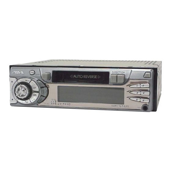
FM/MW/LW CASSETTE CAR STEREO
CT-R442
AEP Model
UK Model
CT-X442
CDS-363AG1-A
Advertisement
Table of Contents

Related Manuals for Aiwa CT-R442


Summary of Contents for Aiwa CT-R442
- Page 1 CT-R442 SERVICE MANUAL AEP Model UK Model Ver 1.0 2003.03 Model Name Using Similar Mechanism CT-X442 Tape Transport Mechanism Type CDS-363AG1-A SPECIFICATIONS RADIO SECTION AUDIO SECTION Max. Power Output: 40 W × 4 channels (FM) Frequency Range: 87.5 MHz – 108 MHz AUX input Intermediate frequency: 10.7 MHz...
-
Page 2: Table Of Contents
CT-R442 TABLE OF CONTENTS Notes on chip component replacement • Never reuse a disconnected chip component. • Notice that the minus side of a tantalum capacitor may be dam- GENERAL ..............3 aged by heat. DISASSEMBLY Flexible Circuit Board Repairing 2-1. -
Page 3: General
CT-R442 SECTION 1 This section is extracted from instruction manual. GENERAL THEFT PROTECTION BASIC OPERATION, Adjusting sound Setting the beep tone AUDIO AND CLOCK Take the front panel with you when leaving the car, and You can select the following modes for adjusting sound Turn off the unit. -
Page 4: Other Functions
CT-R442 TAPE PLAYBACK Changing the Program Types assigned to Displaying a Program Service (PS) name Auto Reverse function You can check the name of currently tuned-in station in When the end of the tape is reached during playback or preset station buttons the display. - Page 5 • Install the unit where it will not hamper the operation of de chaîne audio automobile AIWA le plus proche. the vehicle. • Install the unit where it will not injure the passenger if PRECAUTION there is a sudden stop, like an emergency stop.
- Page 6 CT-R442 E Al conductor de silenciamiento de radio ENGLISH del kit de manos libres para el teléfono celular de coche, etc. CONNECTIONS Cuando el cable de silenciamiento (marrón) para teléfono está conectado al kit de manos libres para teléfono PRECAUTIONS celular de coche, etc., la unidad silencia automáticamente...
-
Page 7: Disassembly
CT-R442 SECTION 2 DISASSEMBLY • This set can be disassembled in the order shown below. 2-1. DISASSEMBLY FLOW FRONT PANEL SECTION (Note: Illustration of disassembly is omitted.) 2-2. MECHANICAL DECK ASSY 2-3. SUB PANEL ASSY (CDS-363AG1-A) (Page 9) (Page 8) 2-4. -
Page 8: Mechanical Deck Assy (Cds-363Ag1-A)
CT-R442 Note: Follow the disassembly procedure in the numerical order given. 2-2. MECHANICAL DECK ASSY (CDS-363AG1-A) 1 screw (PTT2.6 × 4) 2 cover 9 mechanical deck assy (CDS-363AG1-A) 4 two screws (PTT2.6 × 6) 5 connector (CN202) 6 connector (CN201) -
Page 9: Sub Panel Assy
CT-R442 2-3. SUB PANEL ASSY 1 screw (PTT2.6 × 4) 2 cover 3 screw (PTT2.6 × 4) 5 insulation sheet 4 cover 7 two claws 7 two claws 6 two screws (PTT2.6 × 6) 8 sub panel assy... -
Page 10: Main Board
CT-R442 2-4. MAIN BOARD 6 mechanical deck assy (CDS-363AG1-A) 1 two screws (PTT2.6 × 6) 2 connector (CN202) 3 connector (CN201) 4 convex 4 convex 7 main board... -
Page 11: Electrical Adjustment
CT-R442 SECTION 3 ELECTRICAL ADJUSTMENT FM RDS S-METER ADJUSTMENT Adjustment Location: Setting: – MAIN BOARD (Component Side) – FM RF signal MAIN board generator FM/AM antenna (J101) 0.01 µF Carrier frequency : 98.00 MHz Output level : 31 dB (35.5 µV) -
Page 12: Diagrams
CT-R442 SECTION 4 DIAGRAMS 4-1. NOTE FOR PRINTED WIRING BOARDS AND SCHEMATIC DIAGRAMS Note on Printed Wiring Board: Note on Schematic Diagram: • X : parts extracted from the component side. • All capacitors are in µF unless otherwise noted. pF: µµF •... -
Page 13: Printed Wiring Board - Main Board
CT-R442 4-2. PRINTED WIRING BOARD – MAIN Board – • Semiconductor Location J401 F801 Ref. No. Location REAR D101 D102 MAIN BOARD RL– GRN/BLK D151 D402 FL– J101 WHT/BLK (FM/AM ANTENNA) C435 D403 FR– GRY/BLK D501 D-10 JW254 RR– D502... -
Page 14: Schematic Diagram - Main Board (1/3)
CT-R442 4-3. SCHEMATIC DIAGRAM – MAIN Board (1/3) – • • See page 17 for waveform. See page 17 for IC Block Diagrams. (1/3) R151 2.2k TU101 FAE347-E40 (TUNER UNIT) RDS DECODER C151 C152 IC151 SAA6579T J101 C101 (FM/AM ANTENNA) -
Page 15: Schematic Diagram – Main Board (2/3)
CT-R442 4-4. SCHEMATIC DIAGRAM – MAIN Board (2/3) – • See page 17 for IC Block Diagram. (2/3) R403 3.3k C409 C411 C413 0.15 0.15 C415 C401 C403 JC256 R429 L701 JC127 2.2k 4.7µH C701 C417 R701 R405 R415 4.7k... -
Page 16: Schematic Diagram - Main Board (3/3)
CT-R442 4-5. SCHEMATIC DIAGRAM – MAIN Board (3/3) – • See page 17 for Waveform. (Page 15) (3/3) R433 R421 C427 4.7k R521 D402 R424 C429 R422 R419 DAN217 100k R523 100k R915 R902 R916 R917 R929 C432 2.2k 100k... - Page 17 CT-R442 • Waveforms – MAIN Board – – KEY Board – 1 IC151 qf (XOUT) qa IC601 y; (OSC) IC401 LC75374E LFIN 5.3 Vp-p 1.7 Vp-p – LFOUT – – – – LSELO LROUT – 22.8 µs 231 ns –...
-
Page 18: Printed Wiring Boards - Key/Aux Boards
CT-R442 4-6. PRINTED WIRING BOARDS – KEY/AUX Boards – KEY BOARD (COMPONENT SIDE) LED601, 602, 604 − 606 LED602 (KEY ILLUMINATION) LED604 LED606 S603 LED601 LED605 S610 1-687-805- (11) MAIN BOARD CN701 KEY BOARD (CONDUCTOR SIDE) (Page 13) C603 C602... -
Page 19: Schematic Diagram - Key/Aux Boards
CT-R442 4-7. SCHEMATIC DIAGRAM – KEY/AUX Boards – • • See page 17 for Waveform See page 17 for IC Block Diagram. LCD601 LIQUID CRYSTAL DISPLAY J601 AUX GND AUX-L AUX-R LAMP B+ DFP IN R601 R602 2.2k LCD CE R603 2.2k... -
Page 20: Ic Pin Function Description
CT-R442 4-8. IC PIN FUNCTION DESCRIPTION • MAIN BOARD IC901 µPD178076GF-565-3BA (SYSTEM CONTROLLER) Pin No. Pin Name Description Pin No. Pin Name Description EO O PLL phase compartor output to the tuner unit BATT IN Battery voltage detection signal input terminal... - Page 21 CT-R442 Pin No. Pin Name Description — CDS CS Not used — CDS STOP Not used — RADIO CONT Not used — VDDPORT Power supply terminal (+5V) — Ground terminal...
-
Page 22: Exploded Views
CT-R442 SECTION 5 EXPLODED VIEWS NOTE: • -XX and -X mean standardized parts, so they • Items marked “*” are not stocked since they may have some difference from the original are seldom required for routine service. Some one. delay should be anticipated when ordering •... -
Page 23: Front Panel Section
CT-R442 5-2. FRONT PANEL SECTION not supplied not supplied (key board) LCD601 not supplied not supplied not supplied not supplied not supplied not supplied not supplied not supplied not supplied not supplied not supplied supplied not supplied (AUX board) Ref. No. -
Page 24: Electrical Parts List
CT-R442 SECTION 6 ELECTRICAL PARTS LIST NOTE: When indicating parts by reference • Due to standardization, replacements in the • Items marked “*” are not stocked since they number, please include the board. parts list may be different from the parts speci- are seldom required for routine service. - Page 25 CT-R442 MAIN Ref. No. Part No. Description Remark Ref. No. Part No. Description Remark C405 1-162-967-11 CERAMIC CHIP 0.0033uF 10% S616 1-572-596-21 SWITCH, KEY BOARD (TUNER TU) C406 1-162-967-11 CERAMIC CHIP 0.0033uF 10% S621 1-786-491-11 SWITCH, ROTARY (AUDIO CONTROL) C407 1-164-227-11 CERAMIC CHIP 0.022uF...
- Page 26 CT-R442 MAIN Ref. No. Part No. Description Remark Ref. No. Part No. Description Remark C903 1-124-584-00 ELECT 100uF IC401 8-759-487-82 IC LC75374E C904 1-125-691-11 DOUBLE LAYER 0.022F 5.5V IC501 6-703-824-01 IC TA8252H IC901 6-802-759-01 IC uPD178078GF-565-3BA C907 1-162-915-11 CERAMIC CHIP 10PF 0.5PF...
- Page 27 CT-R442 MAIN Ref. No. Part No. Description Remark Ref. No. Part No. Description Remark Q410 8-729-027-44 TRANSISTOR DTC114TKA-T146 R407 1-216-821-11 METAL CHIP 1/10W Q411 8-729-421-22 TRANSISTOR UN2211 R408 1-249-417-11 CARBON 1/4W Q501 8-729-027-24 TRANSISTOR DTA114TKA-T146 R415 1-249-417-11 CARBON 1/4W Q801...
- Page 28 CT-R442 MAIN Ref. No. Part No. Description Remark Ref. No. Part No. Description Remark ACCESSORIES R902 1-247-879-11 CARBON 100K 1/4W ************ R903 1-247-871-11 CARBON 1/4W R904 1-216-864-11 SHORT CHIP 3-252-883-11 MANUAL, INSTRUCTION, INSTALL R905 1-249-417-11 CARBON 1/4W (ENGLISH, SPANISH, FRENCH, GERMAN,...
- Page 29 CT-R442 MEMO...
- Page 30 CT-R442 REVISION HISTORY Clicking the version allows you to jump to the revised page. Also, clicking the version at the upper right on the revised page allows you to jump to the next revised page. Ver. Date Description of Revision...