Table of Contents
Advertisement
Please refer to the original service manual for:
CD Mechanism Unit, Order No. PSG1201019AE
Speaker system SB-MAX200PHK, Order No. PSG1302024CE
TABLE OF CONTENTS
1 Safety Precautions----------------------------------------------- 3
1.1. General Guidelines---------------------------------------- 3
1.2. Before Use -------------------------------------------------- 4
1.3. Before Repair and Adjustment ------------------------- 4
1.4. Protection Circuitry ---------------------------------------- 4
1.5. Caution For Fuse Replacement------------------------ 4
1.6. Safety Parts Information -------------------------------- 5
2 Warning -------------------------------------------------------------- 6
to Electrostatically Sensitive (ES) Devices---------- 6
2.2. Precaution of Laser Diode------------------------------- 7
2.4. Handling Precautions for Traverse Unit-------------- 9
prevention --------------------------------------------------10
3 Service Navigation ----------------------------------------------11
3.1. Service Information -------------------------------------- 11
PAGE
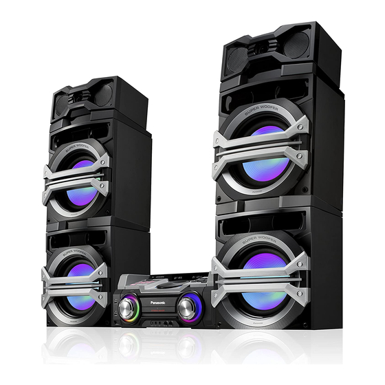
SA-MAX200PH
Model No.
Product Color: (K)...Black Type
3.2. Firmware Update Procedure -------------------------- 12
4 Specifications ---------------------------------------------------- 13
5 General/Introduction------------------------------------------- 14
5.1. Media Information---------------------------------------- 14
6 Location of Controls and Components------------------ 15
6.1. Remote Control Key Button Operation ------------- 15
6.2. Main Unit Key Button Operation---------------------- 16
7 Installation Instructions -------------------------------------- 17
7.1. Speaker and A/C Connection ------------------------- 17
8 Service Mode ----------------------------------------------------- 18
8.1. Cold-Start -------------------------------------------------- 18
8.2. Doctor Mode Table--------------------------------------- 19
8.4. Self-Diagnostic Mode ----------------------------------- 23
8.5. Self-Diagnostic Error Code Table -------------------- 23
8.6. Sales Demonstration Lock Function ---------------- 24
9 Troubleshooting Guide --------------------------------------- 25
© Panasonic Corporation 2013. All rights reserved.
Unauthorized copying and distribution is a violation
of law.
PSG1302027CE
CD Stereo System
PAGE
Advertisement
Table of Contents

Subscribe to Our Youtube Channel
Related Manuals for Panasonic SA-MAX200PH


Summary of Contents for Panasonic SA-MAX200PH
-
Page 1: Table Of Contents
8.5. Self-Diagnostic Error Code Table -------------------- 23 3 Service Navigation ----------------------------------------------11 8.6. Sales Demonstration Lock Function ---------------- 24 3.1. Service Information -------------------------------------- 11 9 Troubleshooting Guide --------------------------------------- 25 © Panasonic Corporation 2013. All rights reserved. Unauthorized copying and distribution is a violation of law. - Page 2 10 Disassembly and Assembly Instructions --------------- 26 16.1. Voltage & Waveform Chart ---------------------------- 95 10.1. Screw Types----------------------------------------------- 26 17 Exploded View and Replacement Parts List---------- 105 10.2. Disassembly Flow Chart-------------------------------- 27 17.1. Exploded View and Mechanical replacement 10.3. Main Components and P.C.B. Locations ----------- 28 Part List --------------------------------------------------- 105 10.4.
-
Page 3: Safety Precautions
1 Safety Precautions 1.1. General Guidelines 1. IMPORTANT SAFETY NOTICE There are special components used in this equipment which are important for safety. These parts are marked by in the Schematic Diagrams, Circuit Board Layout, Exploded Views and Replacement Parts List. It is essential that these critical parts should be replaced with manufacturer’s specified parts to prevent X-RADIATION, shock, fire, or other hazards. -
Page 4: Before Use
1.2. Before Use Be sure to disconnect the mains cord before adjusting the voltage selector as shown in Figure 1-2. Use a minus(-) screwdriver to set the voltage selector (on the rear panel) to the voltage setting for the area in which the unit will be used. -
Page 5: Safety Parts Information
1.6. Safety Parts Information Safety Parts List: There are special components used in this equipment which are important for safety. These parts are marked by in the Schematic Diagrams, Exploded View & Replacement Parts List. It is essential that these critical parts should be replaced with manufacturer’s specified parts to prevent shock, fire or other hazards. -
Page 6: Warning
2 Warning 2.1. Prevention of Electrostatic Discharge (ESD) to Electrostatically Sensi- tive (ES) Devices Some semiconductor (solid state) devices can be damaged easily by static electricity. Such components commonly are called Elec- trostatically Sensitive (ES) Devices. The following techniques should be used to help reduce the incidence of component damage caused by electrostatic discharge (ESD). -
Page 7: Precaution Of Laser Diode
2.2. Precaution of Laser Diode Caution: This product utilizes a laser diode with the unit turned “on”, invisible laser radiation is emitted from the pickup lens. Wavelength: 790 nm (CD) Maximum output radiation power from pickup: 100 µW/VDE Laser radiation from the pickup unit is safety level, but be sure the followings: 1. -
Page 8: Service Caution Based On Legal Restrictions
2.3. Service caution based on Legal restrictions 2.3.1. General description about Lead Free Solder (PbF) The lead free solder has been used in the mounting process of all electrical components on the printed circuit boards used for this equipment in considering the globally environmental conservation. The normal solder is the alloy of tin (Sn) and lead (Pb). -
Page 9: Handling Precautions For Traverse Unit
2.4. Handling Precautions for Traverse Unit The laser diode in the optical pickup unit may break down due to static electricity of clothes or human body. Special care must be taken avoid caution to electrostatic breakdown when servicing and handling the laser diode in the traverse unit. Cautions to Be Taken in Handling the Optical Pickup Unit 2.4.1. -
Page 10: Grounding For Electrostatic Breakdown Prevention
2.5. Grounding for electrostatic breakdown prevention • As for parts that use optical pick-up (laser diode), the optical pick-up is destroyed by the static electricity of the working environ- ment. Repair in the working environment that is grounded. 2.5.1. Worktable grounding •... -
Page 11: Service Navigation
3 Service Navigation 3.1. Service Information This service manual contains technical information which will allow service personnel’s to understand and service this model. Please place orders using the parts list and not the drawing reference numbers. If the circuit is changed or modified, this information will be followed by supplement service manual to be filed with original service manual. -
Page 12: Firmware Update Procedure
3.2. Firmware Update Procedure Start Write encrypted UPD bin to CD-R Turn On main set Insert CD-R (with UPD bin) and close TOC reading "CHECKING" "NO PLAY" process end Writing starts: "0%" -> "20%" -> "40%" -> "60%" -> "80%" -> 100%" "GOOD"... -
Page 13: Specifications
4 Specifications Recording file format MP3 (*.mp3) General Power supply AC 110 to 127/220 to 240 V, Amplifier section 50/60 Hz RMS output power stereo mode Power consumption 195 W Front Speaker SB-MAF200 Power consumption in 0.3 W (approximate) 300 W per channel (3Ω), 1 kHz, 30% THD standby mode Subwoofer Speaker SB-MAY200 Dimensions (W x H x D) -
Page 14: General/Introduction
5 General/Introduction 5.1. Media Information... -
Page 15: Location Of Controls And Components
6 Location of Controls and Components 6.1. Remote Control Key Button Operation... -
Page 16: Main Unit Key Button Operation
6.2. Main Unit Key Button Operation... -
Page 17: Installation Instructions
7 Installation Instructions 7.1. Speaker and A/C Connection... -
Page 18: Service Mode
8 Service Mode 8.1. Cold-Start Here is the procedure to carry out cold-start or initialize to shipping mode. 1. Unplug AC power cord 2. Press & hold [POWER] button 3. Plug AC power cord while [POWER] button being pressed FL Display will show “_ _ _ _ _ _ _ _” 4. -
Page 19: Doctor Mode Table 1
8.2. Doctor Mode Table 8.2.1. Doctor Mode Table 1 Item Key Operation FL Display Mode Name Description Front Key Doctor Mode To enter into Doctor Mode In CD Mode: 1. Press [ ] button on main unit follow by [4] and [7] on remote control. - Page 20 8.2.2. Doctor Mode Table 2 Item Key Operation FL Display Mode Name Description Front Key Volume Setting To check the volume setting of the In Doctor Mode: Check main unit. 1. Press [7], [8], [9] button on the remote control. Press [7]: VOL50 Volume Press [8]: VOL35...
- Page 21 8.2.3. Doctor Mode Table 3 Item Key Operation FL Display Mode Name Description Front Key To display result of In Doctor Mode : Self- Adjustment self-adjustment for CD. 1. Press [10] [4] button Test on the remote control. Display of auto adjustment result Reference table: ERROR Code...
-
Page 22: Reliability Test Mode (Cd Mechanism Unit)
8.3. Reliability Test Mode (CD Mechanism Unit) Below is the process flow chart of the aging test for the CD Mechanism Unit . OPEN First Track Operation Access OPEN wait First Track for 1 s Play 5 s CLOSE Count up Last Track Operation Access... -
Page 23: Self-Diagnostic Mode
8.4. Self-Diagnostic Mode Item Key Operation FL Display Mode Name Description Front Key Self Diagnostic To enter into self diagnostic checking Step 1: Select CD mode Mode (Ensure no disc is inserted). Step 2: Press & hold [ ] button follow by [ ] on main unit for 2 seconds. -
Page 24: Sales Demonstration Lock Function
8.5.2. CD Mechanism Error Code Table (CD Mechanism Unit) Error Code Diagnostic Contents Description of error Automatic FL Display Remarks CD H15 CD Open Abnormal During operation Press [ ] on main unit for POS_SW_R On fail to be next error. detected with 4 sec. -
Page 25: Troubleshooting Guide
9 Troubleshooting Guide "Contents for this section is not available at time of issue"... -
Page 26: Disassembly And Assembly Instructions
10 Disassembly and Assembly Instructions Caution Note: • This section describes the disassembly and/or assembly procedures for all major printed circuit boards & main components for the unit. (You may refer to the section of “Main components and P.C.B Locations” as described in the service manual) •... -
Page 27: Disassembly Flow Chart
10.2. Disassembly Flow Chart 10.4. Top Cabinet 10.21. SMPS P.C.B. 10.17. CD Mechanism 10.5. Front Panel Unit and Voltage Selector Unit P.C.B. 10.22. Switching 10.25. CD Interface 10.6. FL Display P.C.B. Regulator (Q5700) P.C.B. 10.7. Illumination 10.23. Diode (D5801) 10.18. Rear Panel Button P.C.B. -
Page 28: Main Components And P.c.b. Locations
10.3. Main Components and P.C.B. Locations... -
Page 29: Disassembly Of Top Cabinet
10.4. Disassembly of Top Cabinet Step 5 Slightly lift up the Top Cabinet. Step 6 Remove the Top Cabinet. Step 1 Remove 3 screws. Step 2 Remove 3 screws. Caution: During assembling, ensure that the catches of the Top Cabinet catches are properly located & inserted into the Front Panel Unit as shown. -
Page 30: Disassembly Of Front Panel Unit
10.5. Disassembly of Front Panel Step 7 Remove the Front Panel Unit Unit • Refer to “Disassembly of Top Cabinet”. Step 1 Remove 1 screw. Step 2 Detach 10P FFC at the connector (CN2002) on Main P.C.B.. Step 3 Detach 11P Cable at the connector (CN2001) on Main P.C.B.. -
Page 31: Disassembly Of Fl Display P.c.b
10.6. Disassembly of FL Display Caution: During assembling, ensure that the FL Display P.C.B. is properly located and fully catched onto the Front P.C.B. Panel Unit. • Refer to “Disassembly of Top Cabinet”. • Refer to “Disassembly of Front Panel Unit”. Step 1 Remove 6 screws. -
Page 32: Disassembly Of Control P.c.b
10.8. Disassembly of Control P.C.B. Step 4 Remove 4 screws. Step 5 Detach 6P FFC at a connector (CN6111) on the Control • Refer to “Disassembly of Top Cabinet”. Jog LED P.C.B.. • Refer to “Disassembly of Front Panel Unit”. •... -
Page 33: Disassembly Of Control Jog Led P.c.b
Step 7 Detach 12P Cable at a connector (CN6200) on the Con- 10.9. Disassembly of Control Jog trol P.C.B.. LED P.C.B. • Refer to “Disassembly of Top Cabinet”. • Refer to “Disassembly of Front Panel Unit”. • Refer to “Disassembly of FL Display P.C.B.”. •... - Page 34 Step 2 Remove 2 screws. Step 9 Release catches in the sequences of 1 to 4. Step 3 Remove the Side Cover. Step 4 Remove 5 screws. Step 5 Detach 6P FFC at a connector (CN6112) on the Volume Jog LED P.C.B.. Step 6 Detach 4P Cable at a connector (CN5700) on the LED P.C.B..
-
Page 35: Disassembly Of Volume Jog Led P.c.b
10.11. Disassembly of Volume Jog 10.12. Disassembly of Remote Sensor LED P.C.B. P.C.B. • Refer to “Disassembly of Top Cabinet”. • Refer to “Disassembly of Top Cabinet”. • Refer to “Disassembly of Front Panel Unit”. • Refer to “Disassembly of Front Panel Unit”. •... -
Page 36: Disassembly Of Mic P.c.b
10.14. Disassembly of Mic P.C.B. 10.15. Disassembly of LED P.C.B. • Refer to “Disassembly of Top Cabinet”. • Refer to “Disassembly of Top Cabinet”. • Refer to “Disassembly of Front Panel Unit”. • Refer to “Disassembly of Front Panel Unit”. Step 1 Remove the Mic Knob. -
Page 37: Disassembly Of Cd Lid
10.16. Disassembly of CD Lid Step 2 Remove the CD Lid as arrow shown. Step 3 Release the CD Lid from the guide. • Refer to “Disassembly of Top Cabinet”. • Refer to “Disassembly of Front Panel Unit”. Step 1 Remove the spring as arrow shown in order of sequence (1) to (3). -
Page 38: Disassembly Of Rear Panel
10.17. Disassembly of Rear Panel Step 5 Release 2 tabs. Step 6 Remove the Rear Panel. • Refer to “Disassembly of Top Cabinet”. Step 1 Remove 9 screws. Step 2 Detach the Voltage Selector P.C.B. from Rear Panel. Step 3 Release catches on the Fan Units. Step 4 Remove the Fan Units. -
Page 39: Disassembly Of Cd Mechanism Unit
10.18. Disassembly of CD Mecha- 10.19. Disassembly of Main P.C.B. nism Unit • Refer to “Disassembly of Top Cabinet”. • Refer to “Disassembly of Front Panel Unit”. • Refer to “Disassembly of Top Cabinet”. • Refer to “Disassembly of Rear Panel”. •... -
Page 40: Disassembly Of Digital Amplifier Ic (Ic2501/Ic2502/Ic2503/Ic2504)
10.20. Disassembly of Digital Ampli- Step 4 Desolder the pins of the Digital Amplifier IC. Step 5 Remove the Digital Amplifier IC. fier IC (IC2501/IC2502/IC2503/ IC2504) • Refer to “Disassembly of Main P.C.B.”. 10.20.1. Disassembly of Digital Amplifier IC (IC2501/IC2502/IC2503/IC2504) Caution: Handle the Main P.C.B. -
Page 41: Disassembly Of Smps P.c.b. And Voltage Selector P.c.b
Step 3 Fix Heatsink spacers onto Main Heatsink.. 10.21. Disassembly of SMPS P.C.B. Caotion: Ensure that the Heatsink Spacers are properly and Voltage Selector P.C.B. located and seated flatly onto Main Heatsink. Step 4 Apply grease to the Main Heatsink as indicate in the dia- •... - Page 42 Step 5 Detach the Voltage Selector P.C.B. from the rear panel Step 8 Remove the SMPS P.C.B.. as arrow shown. Caution: During assembling, ensure that the SMPS P.C.B. is properly located & fully seated onto the Inner Chassis Unit. Step 6 Remove 2 screws Step 7 Remove the Inner Fan Unit.
-
Page 43: Replacement Of Switching Regulator (Q5700)
10.22. Replacement of Switching Reg- Step 3 Remove the Heatsink A with the Switching Regulator (Q5700). ulator (Q5700) Step 4 Remove 1 screw. • Refer to “Disassembly of SMPS P.C.B.”. Step 5 Remove the Switching Regulator (Q5700) from the Heatsink A. 10.22.1. - Page 44 10.22.2. Assembly of Switching Regulator Step 4 Solder pins of the Switching Regulator (Q5700) on the solder side of the SMPS P.C.B.. (Q5700) Step 5 Solder pins of the Heatsink A on the solder side of the Step 1 Apply grease to the Heatsink A. SMPS P.C.B..
-
Page 45: Replacement Of Diode (D5801)
10.23. Replacement of Diode (D5801) Step 3 Remove 1 screw at the Diode (D5801). Step 4 Remove the Diode (D5801) from the SMPS P.C.B.. • Refer to “Disassembly of SMPS P.C.B.”. Caution: Avoid touching the Heatsink B due to its high temperature after prolonged use. -
Page 46: Replacement Of Diode (D5802)
Step 4 Solder pins of the Diode (D5801) on the solder side of 10.24. Replacement of Diode (D5802) the SMPS P.C.B.. • Refer to “Disassembly of SMPS P.C.B.”. Step 5 Solder pins of the Heatsink B. 10.24.1. Disassembly of Diode (D5802) Step 1 Desolder pins of the Diode (D5802) on the solder side of the SMPS P.C.B. -
Page 47: Disassembly Of Cd Interface P.c.b
10.24.2. Assembly of Diode (D5802) 10.25. Disassembly of CD Interface Step 1 Apply grease to the Heatsink B. P.C.B. Step 2 Screw the Diode (D5802) to the Heatsink B. • Refer to “Disassembly of Top Cabinet”. Caution: Ensure the Diode (D5802) is tightly screwed to the •... -
Page 48: Service Position
11 Service Position Note: For description of the disassembly procedures, see Step 12 Attach 2P Cable at a connector (CN6800) on the Illu- the Section 10. mination Button P.C.B.. Step 13 Attach 8P Cable at a connector (CN6103) on the Mic 11.1. -
Page 49: Checking Of Main P.c.b. (Side B)
11.2. Checking of Main P.C.B. (Side Step 12 Attach 10P FFC at a connector (CN2002) on the Main P.C.B.. Step 13 Attach 11P Cable at a connector (CN2001) on the Step 1 Remove Top Cabinet. Main P.C.B.. Step 2 Remove Front Panel Unit. Step 14 Attach 30P FFC at a connector (CN2004) on the Main Step 3 Remove Rear Panel. -
Page 50: Checking Of Main P.c.b. (Side A)
11.3. Checking of Main P.C.B. (Side Step 13 Attach 10P FFC at a connector (CN2002) on the Main P.C.B.. Step 14 Attach 11P Cable at a connector (CN2001) on the Step 1 Remove Top Cabinet. Main P.C.B.. Step 2 Remove Front Panel Unit. Step 15 Attach 30P FFC at a connector (CN2004) on the Main Step 3 Remove Rear Panel. -
Page 51: Checking Of Smps P.c.b
11.4. Checking of SMPS P.C.B. Step 1 Remove Top Cabinet. Step 2 Remove SMPS P.C.B.. Step 3 Attach 13P Cable at the connector (CN5802) on the SMPS P.C.B.. Step 4 Upset the SMPS P.C.B.. Step 5 Attach 2P Wire at the connector (CN2006) on the Main P.C.B.. -
Page 53: Block Diagram
OPEN SW CD OPEN SW CN7001 CLOSE SW CLOSE SW CN7002 FP8252 CLOSE SW CN2006 CD CLOSE SW POSITIVE CN2006 NEGATIVE CD INTERFACE P.C.B. NOTE: “ * ” REF IS FOR INDICATION ONLY SA-MAX200PH SERVO & SYSTEM CONTROL (1/3) BLOCK DIAGRAM... - Page 54 CN2004 CN6001 CN6002 CN6102 ZJ6100* CN6200 KEY2 KEY2 KEY2 98 REMOTE SENSOR P.C.B. IR6500 REMOTE SENSOR FP3001 ZJ6101* CN6105 CN6500 RMT 86 +3.3V NOTE: “ * ” REF IS FOR INDICATION ONLY SA-MAX200PH SERVO & SYSTEM CONTROL (2/3) BLOCK DIAGRAM...
- Page 55 CN6102 ZJ6700* CN6700 Z8 8 D6701 CN2002 CN6000 CN6002 CN6102 ZJ6700* CN6700 Z9 6 D6700 CN2002 CN6000 CN6002 CN6102 ZJ6700* CN6700 Z10 5 NOTE: “ * ” REF IS FOR INDICATION ONLY SA-MAX200PH SERVO & SYSTEM CONTROL (3/3) BLOCK DIAGRAM...
-
Page 56: Ic Terminal Chart
DQ2 / DQ13 5 / 46 DQ3 / DQ12 6 / 45 DQ4 / DQ11 8 / 43 DQ5 / DQ10 9 / 42 DQ6 / DQ9 11 / 40 DQ7 / DQ8 12 / 39 SA-MAX200PH IC TERMINAL CHART... -
Page 57: Audio
CN2004 MPORT R MPORT R MUSIC PORT MPORT L CN6103 ZJ6300* CN6102 CN6002 CN6001 CN2004 MPORT L VOLUME P.C.B. FL DISPLAY P.C.B. IC2002 C0JBAR000367 AUDIO SELECTOR NOTE: “ * ” REF IS FOR INDICATION ONLY SA-MAX200PH AUDIO (1/2) BLOCK DIAGRAM... - Page 58 DIGITAL AMPLIFIER INPUT B BST A OUT A OUT A INPUT A OUT B BST B BST C /RST JK2500 OUT C SUBWOOFER /CLIP JK2500 (2 ) OUT D /OTW OUT D /FAULT BST D SA-MAX200PH AUDIO (2/2) BLOCK DIAGRAM...
-
Page 59: Power Supply
DRIVE D5728 Q5711 CURRENT LIMITING SWITCH CN5802 CN2008 +36V SENSE +36V SENSE PW +36V 5,6,7 5,6,7 FEEDBACK CIRCUIT IC5801 C0DAZYY00039 SHUNT REGULATOR PC5720 PRIMARY SECONDARY NOTE: “ * ” REF IS FOR INDICATION ONLY SA-MAX200PH POWER SUPPLY (1/2) BLOCK DIAGRAM... - Page 60 VBUS B VBUS B CN2001 ZJ6400* VBUS B VBUS B VBUS B 4 IN OUT 5 3 FLG 1 CTL IC2004 C0DBZYY00592 HIGH SIDE SWITCH NOTE: “ * ” REF IS FOR INDICATION ONLY SA-MAX200PH POWER SUPPLY (2/2) BLOCK DIAGRAM...
-
Page 61: Wiring Connection Diagram
CN6102 1 2 3 4 5 CN6105 ZJ6101* ZJ6700* VOLUME P.C.B. ZJ6300* P5701 (SOLDER SIDE) CN5802 AC IN ~ 110-127V/220-240V 50/60Hz CN6800 ILLUMINATION BUTTON P.C.B. (SOLDER SIDE) NOTE: " * " REF IS FOR INDICATION ONLY. SA-MAX200PH WIRING CONNECTION DIAGRAM... -
Page 63: Schematic Diagram
14 Schematic Diagram • Voltage and signal line : +B signal line : -B signal line 14.1. Schematic Diagram Notes : CD Audio input signal line : Mic/Tuner/Music Port/AUX input signal line • This schematic diagram may be modified at any time : Audio output signal line with the development of new technology. -
Page 65: Main (Cd Servo/Micon/Damp) Circuit
152 153 LB8501 C8054 C8042 J0JHC0000045 PW_3R3V_DIG C8504 C8507 C8506 C8501 DGND MI: MAIN (MICON): SCHEMATIC DIAGRAM - 5 ~ 10 DA: MAIN (DAMP): SCHEMATIC DIAGRAM - 11 ~ 14 TO MAIN (CD SERVO) CIRCUIT (3/4) SA-MAX200PH MAIN (CD SERVO) CIRCUIT... - Page 66 LASER DRIVE K8351 K8350 G1C100KA0101 GND-LD R8212 C8259 C8202 PW_3R3V_CD D8250 C8260 DZ2J056M0L 0.01 C8201 PD_GND LB8202 D8251 DA2J10100L G1C100KA0101 PW_+5R4V MI: MAIN (MICON): SCHEMATIC DIAGRAM - 5 ~ 10 TO MAIN (CD SERVO) CIRCUIT (4/4) SA-MAX200PH MAIN (CD SERVO) CIRCUIT...
- Page 67 PW_3R3V_DIG CD_MLD R8210 R8211 R8010 2.7K 100K C8013 C8018 R8011 R8002 6.3V100 0.33 100K NRST CD_RESET C8078 C8079 C8068 3300P R8005 R8006 X8101 H0J338300002 C8015 C8016 MI: MAIN (MICON): SCHEMATIC DIAGRAM - 5 ~ 10 SA-MAX200PH MAIN (CD SERVO) CIRCUIT...
- Page 68 R8258 R8261 R8260 R8259 4.7K R8264 1.2K PW_3R3V_CD R8263 C8256 C8261 1000P K8208 C8262 C8252 C8251 CHASSIS GND 10V100 0.01 LB8252 J0JHC0000045 PW_+5R4V LB8251 J0JHC0000045 PW_+5R4V MI: MAIN (MICON): SCHEMATIC DIAGRAM - 5 ~ 10 SA-MAX200PH MAIN (CD SERVO) CIRCUIT...
- Page 69 DIAGRAM - 17 R2070 4.7K QR2001 R2071 3.9K B1GBCFJJ0051 SWITCH R2114 X2002 H2B800400007 TO MAIN (MICON) CD: MAIN (CD SERVO): SCHEMATIC DIAGRAM - 1 ~ 4 CIRCUIT (4/6) DA: MAIN (DAMP): SCHEMATIC DIAGRAM - 11 ~ 14 SA-MAX200PH MAIN (MICON) CIRCUIT...
- Page 70 6.3V220 100K C2117 R2232 R2231 R2236 MGND TO MAIN (MICON) CIRCUIT (3/6) TO MAIN (MICON) CD: MAIN (CD SERVO): SCHEMATIC DIAGRAM - 1 ~ 4 CIRCUIT (5/6) DA: MAIN (DAMP): SCHEMATIC DIAGRAM - 11 ~ 14 SA-MAX200PH MAIN (MICON) CIRCUIT...
- Page 71 CN3104 SWITCH LED_DRV_RST TO RIGHT SUBWOOFER (SB-MAY200) TO MAIN (MICON) CIRCUIT (2/6) TO MAIN (MICON) CD: MAIN (CD SERVO): SCHEMATIC DIAGRAM - 1 ~ 4 CIRCUIT (6/6) DA: MAIN (DAMP): SCHEMATIC DIAGRAM - 11 ~ 14 SA-MAX200PH MAIN (MICON) CIRCUIT...
- Page 72 C2010 AM ANT AM ANT AM ANT R2012 R2015 4.7K 4.7K R2018 TU_SDA R2019 TU_SCL R2020 TU_RST CD: MAIN (CD SERVO): SCHEMATIC DIAGRAM - 1 ~ 4 DA: MAIN (DAMP): SCHEMATIC DIAGRAM - 11 ~ 14 SA-MAX200PH MAIN (MICON) CIRCUIT...
- Page 73 C2049 +1.8V VOLTAGE REGULATOR 1000P C3218 C2041 C2035 DGND R2081 R3223 C2075 C2078 LB3201 J0JBC0000134 PW_CD_3R3V R3224 CD: MAIN (CD SERVO): SCHEMATIC DIAGRAM - 1 ~ 4 DA: MAIN (DAMP): SCHEMATIC DIAGRAM - 11 ~ 14 SA-MAX200PH MAIN (MICON) CIRCUIT...
- Page 74 PWGND RT/CLK R3354 Q2023 C3307 C2080 C2084 C2086 C2087 C2092 R2188 4700P B1GBCFJJ0041 6.3V1000 10V220 270K SWITCH DGND CD: MAIN (CD SERVO): SCHEMATIC DIAGRAM - 1 ~ 4 DA: MAIN (DAMP): SCHEMATIC DIAGRAM - 11 ~ 14 SA-MAX200PH MAIN (MICON) CIRCUIT...
- Page 75 SP_SW2+(2) R3612 /FAULT PVDD_CD /OTW OUT_D /CLIP OUT_D R3664 C2733 0.033 BST_C C2732 0.033 PW_+12V GVDD_CD BST_D C2730 DGND R3654 R3653 ZJGND_HS4 MI: MAIN (MICON): SCHEMATIC DIAGRAM - 5 ~ 10 TO MAIN (DAMP) CIRCUIT (3/4) SA-MAX200PH MAIN (DAMP) CIRCUIT...
- Page 76 TO MAIN (DAMP) SP_SW2- CIRCUIT (1/4) SP_SW3+(1) R2595 R2655 100K C2656 C2684 1000P 0.01 C2657 0.01 C2685 1000P R2656 R2596 100K C2693 1000P SP_SW3-(1) MI: MAIN (MICON): SCHEMATIC DIAGRAM - 5 ~ 10 TO MAIN (DAMP) CIRCUIT (4/4) SA-MAX200PH MAIN (DAMP) CIRCUIT...
- Page 77 FL-_LO INPUT_D PVDD_CD 0.22 R3631 SP_FL+LO DAMP_FAULT /FAULT PVDD_CD DAMP_OTW /OTW OUT_D DAMP_CLIP /CLIP OUT_D R3667 C2552 0.033 BST_C C2549 0.033 GVDD_CD BST_D C2714 R3652 R3651 ZJGND_HS3 MI: MAIN (MICON): SCHEMATIC DIAGRAM - 5 ~ 10 SA-MAX200PH MAIN (DAMP) CIRCUIT...
- Page 78 R2663 100K C2652 0.01 C2653 0.01 R2592 R2664 100K SP_SW2-(2) C2689 1000P SP_SW+(2) C2690 1000P R2593 C2654 0.01 C2655 0.01 R2594 SP_SW-(2) C2691 1000P C2679 R3501 DGND MI: MAIN (MICON): SCHEMATIC DIAGRAM - 5 ~ 10 SA-MAX200PH MAIN (DAMP) CIRCUIT...
-
Page 79: Fl Display Circuit
KEY1_A LED_DIMMER LED_DIMMER R6013 R6034 R6006 R6007 R6008 R6009 R6010 R6011 1.2K 1.5K 2.2K 3.3K 4.7K 6.8K S6003 S6000 S6001 S6002 S6004 S6005 S6006 MEMORY 1 MEMORY 2 MEMORY 3 MEMORY 4 MEMORY 5 MEMORY 6 SA-MAX200PH FL DISPLAY CIRCUIT... - Page 80 KEY2 TO FL DISPLAY KEY2 CIRCUIT (1/2) KEY3 KEY3 DGND DGND PW_SYS3R3V SYS3.3V LED_DIMMER LED_DIMMER PW_CD3R3V CD3.3V R6015 R6022 D6014 D6013 DA2J10100L DA2J10100L D6005 D6002 B3AKA0000022 D6019...MAX200 B3AKA0000022 B0EAMM000057 CK6003 CK6001 R6020 D6018 D6017 DA2J10100L DA2J10100L SA-MAX200PH FL DISPLAY CIRCUIT...
-
Page 81: Volume Circuit
KEY1_B MIC_SW LED CIRCUIT MIC CIRCUIT PW_+12V (CN6700) +12V (CN6103) MPORT_SW MPORT_SW IN SCHEMATIC IN SCHEMATIC MPORT_L MPORT_L DIAGRAM - 20 DIAGRAM - 19 MPORT_GND MPORT_GND MPORT_R MPORT_R NOTE: “ * ” REF IS FOR INDICATION ONLY SA-MAX200PH VOLUME CIRCUIT... -
Page 82: Control & Usb Circuit
MAIN (MICON) D5V PLAY CIRCUIT (CN2001) D5V REC IN SCHEMATIC VBUS_A DIAGRAM - 7 CN6401 DGND VBUSA D5V PLAY USB PORT A (PLAY) DGND D6401 B3ABA0000187 NOTE: “ * ” REF IS FOR INDICATION ONLY SA-MAX200PH CONTROL / USB CIRCUIT... -
Page 83: Mic Circuit
MPORT_L VOLUME CIRCUIT MPORT_SW (ZJ6300*) PW_+12V +12V IN SCHEMATIC DIAGRAM - 17 MIC_SW MIC_SW MIC_GND MIC_SW MIC_GND C6324 C6323 0.01 390P ZJ6301* TO SMPS CHASSIS_GND CHASSIS_GND CHASSIS GND NOTE: “ * ” REF IS FOR INDICATION ONLY SA-MAX200PH MIC CIRCUIT... -
Page 84: Remote Sensor, Led & Illumination Button Circuit
(CN6105) IN SCHEMATIC DIAGRAM - 17 ILLUMINATION BUTTON CIRCUIT S6800 ILLUMINATION CN6800 VOLUME CIRCUIT KEY3_A (CN6108) DGND IN SCHEMATIC DIAGRAM - 17 NOTE: “ * ” REF IS FOR INDICATION ONLY SA-MAX200PH REMOTE SENSOR / LED / ILLUMINATION BUTTON CIRCUIT... -
Page 85: Smps Circuit
R5728 CURRENT C5720 100P 100K LIMITING SWITCH D5724 DA2J10100L D5722 DZ2J200M0L C5728 1000P D5723 C5721 220P C5722 DA2J10100L 1000P PC5701 FEEDBACK D5727 DA2J10100L R5810 QR5810 B1GBCFLL0037 PCONT SWITCH SA-MAX200PH SMPS CIRCUIT NOTE: “ * ” REF IS FOR INDICATION ONLY... - Page 86 SWITCHING MODE POWER SUPPLY CONTROL TO SMPS R5895 R5893 CIRCUIT (1/2) C5898 R5892 R5786 C5794 R5795 D5793 200K 1000P 470K B0HAMP000094 C5790 2200P R5797 C5899 R5891 10V220 C5796 C5795 SA-MAX200PH SMPS CIRCUIT NOTE: “ * ” REF IS FOR INDICATION ONLY...
-
Page 87: Voltage Selector, Control Jog Led, Volume Jog Led & Cd Interface Circuit
IN SCHEMATIC OPEN_SW IN SCHEMATIC DIAGRAM - 17 LDM- S7201 DIAGRAM - 4 D6906 LDM+ DA2J10100L RESET TRV- TRV+ D6206 B3AZB0000101 CKA2 CKA1 M7301* TRAVERSE MOTOR SA-MAX200PH VOLTAGE SELECTOR / CONTROL JOG LED / VOLUME JOG LED / CD INTERFACE CIRCUIT... -
Page 88: Printed Circuit Board
R2055 R2060 C2051 R2048 C3000 Q2003 R2109 R2173 R2163 R3022 R3007 R2056 R2157 Q2004 C2082 R2161 QR2003 R2171 R2158 R2155 R3016 IC2010 R2172 R2162 R2156 D2003 R3017 R3018 LB8254 QR2002 R2154 C8265 C2081 3620A-1 3620A-1 (SIDE A) SA-MAX200PH MAIN P.C.B. - Page 89 1-GND 4-GND CN3104 2-R-_LOW 4-R-_MID LOW 6-R-_HIGH 8-L-_MID LOW 10-L-_HIGH 12-L-_LOW CN3103 CN3102 (TO RIGHT SUBWOOFER (TO RIGHT SUBWOOFER (TO LEFT SUBWOOFER JK2002 (SB-MAX200)) (SB-MAX200)) (SB-MAX200)) TO SPEAKERS AUX IN AM ANT FM ANT (SUBWOOFER/FRONT) (SIDE B) SA-MAX200PH MAIN P.C.B.
-
Page 90: Fl Display & Volume P.c.b
(STOP/TUNE MODE) W6115 W6121 W6149 S6106 W6113 (MEMORY R6107 REC/PAUSE) W6168 S6101 W6167 (RADIO/EXT-IN) CN6105 R6119 R6118 ZJ6300* C6103 ZJ6101* ZJ6700* 3641AB-1 3641AB-1 S6107 (CD OPEN/CLOSE) NOTE: " * " REF IS FOR INDICATION ONLY. SA-MAX200PH FL DISPLAY / VOLUME P.C.B. -
Page 91: Control, Mic, Usb, Remote Sensor, Led & Illumination Button P.c.b
USB PORT A IC6300 CN6800 CN6103 R6301 (REC/PLAY) (PLAY) L6302 R6302 LB6303 C6314 C6311 R6305 R6304 MUSIC PORT NOTE: " * " REF IS FOR INDICATION ONLY. SA-MAX200PH CONTROL / MIC / USB / REMOTE SENSOR / LED / ILLUMINATION BUTTON P.C.B. -
Page 92: Smps & Voltage Selector P.c.b
R5893 W5528 R5909 CN5802 C5701 C5896 W5529 R5700 C5895 AC IN ~ DZ5701 Q5898 W5908 110-127V/220-240V W5530 50/60Hz ZA5702 T10AH 250V ZA5701 W5531 3619CA-1 3619CA-1 NOTE: " * " REF IS FOR INDICATION ONLY SA-MAX200PH SMPS / VOLTAGE SELECTOR P.C.B. -
Page 93: Control Jog Led, Volume Jog Led & Cd Interface P.c.b
(SIDE B) VOLUME JOG LED P.C.B. (REP4915AB) 3662AB 3662AB 3662AB 3662AB D6204 D6205 CN6112 D6906 D6206 (SIDE A) (SIDE B) NOTE: " * " REF IS FOR INDICATION ONLY SA-MAX200PH CONTROL JOG LED / VOLUME JOG LED / CD INTERFACE P.C.B. -
Page 95: Voltage & Waveform Chart
CD PLAY STANDBY IC2005 REF NO. MODE CD PLAY 12.0 12.0 12.0 STANDBY 12.0 12.0 12.0 IC2005 REF NO. MODE CD PLAY STANDBY IC2006 REF NO. MODE POWER ON STANDBY IC2006 REF NO. MODE POWER ON STANDBY SA-MAX200PH MAIN P.C.B. - Page 96 STANDBY IC2008 REF NO. MODE CD PLAY STANDBY IC2009 REF NO. MODE POWER ON STANDBY IC2010 REF NO. MODE POWER ON 15.3 STANDBY 15.3 IC2011 REF NO. MODE POWER ON 18.7 37.4 12.6 STANDBY 18.7 37.4 12.6 SA-MAX200PH MAIN P.C.B.
- Page 97 18.1 18.1 37.4 37.4 37.4 18.1 18.1 37.4 37.4 37.4 18.1 18.1 STANDBY 11.8 29.0 29.0 18.1 18.1 37.4 37.4 37.4 18.1 18.1 37.4 37.4 37.4 18.1 18.1 REF NO. IC2503 MODE CD PLAY 29.0 29.0 STANDBY 29.0 29.0 SA-MAX200PH MAIN P.C.B.
- Page 98 POWER ON STANDBY REF NO. IC3102 MODE POWER ON STANDBY REF NO. IC8001 MODE CD PLAY STANDBY REF NO. IC8001 MODE CD PLAY STANDBY REF NO. IC8001 MODE CD PLAY STANDBY IC8001 REF NO. MODE CD PLAY STANDBY SA-MAX200PH MAIN P.C.B.
- Page 99 CD PLAY STANDBY IC8051 REF NO. MODE CD PLAY STANDBY IC8051 REF NO. MODE CD PLAY STANDBY IC8251 REF NO. MODE CD PLAY STANDBY REF NO. IC8251 MODE CD PLAY STANDBY IC8401 REF NO. MODE CD PLAY STANDBY SA-MAX200PH MAIN P.C.B.
- Page 100 Q2001 Q2002 Q2003 Q2004 REF NO. MODE POWER ON 15.3 15.3 15.3 STANDBY 15.3 15.4 15.3 Q2005 Q2006 Q2007 Q2008 Q2009 REF NO. MODE POWER ON 15.3 11.6 15.3 11.6 15.3 STANDBY 15.3 11.6 15.3 11.6 15.3 SA-MAX200PH MAIN P.C.B.
- Page 101 -19.5 -21.5 -23.4 -21.5 -15.9 -19.6 -17.8 -21.5 -21.5 -21.5 -21.5 -21.5 -21.5 -21.5 -21.5 -21.5 -21.5 -21.5 -21.5 -21.5 IC6000 REF NO. MODE POWER ON -21.6 -21.9 STANDBY -21.6 -21.9 Q6001 REF NO. MODE POWER ON 15.1 STANDBY 15.1 SA-MAX200PH FL DISPLAY P.C.B. 16.1.9. Volume P.C.B. QR6100 REF NO. MODE POWER ON STANDBY SA-MAX200PH VOLUME P.C.B.
- Page 102 16.1.10. Mic P.C.B. IC6300 REF NO. MODE POWER ON 12.1 12.1 STANDBY 12.1 12.1 SA-MAX200PH MIC P.C.B. 16.1.11. SMPS P.C.B. IC5701 REF NO. MODE POWER ON 18.9 STANDBY 18.9 REF NO. IC5790 MODE POWER ON 0.2 163.0 STANDBY 0.2 163.0 IC5801 REF NO.
- Page 103 16.1.12. Waveform Table 0.1Vp-p(200usec/div) 1.6Vp-p(20nsec/div) 4.8Vp-p(20nsec/div) 3.8Vp-p(50nsec/div) 4Vp-p(50nsec/div) 2Vp-p(10usec/div) 3.8Vp-p(10usec/div) 1.8Vp-p(50usec/div) 3.2Vp-p(1usec/div) 5.2Vp-p(1usec/div) 1.6Vp-p(1usec/div) 28Vp-p(500nsec/div) 28Vp-p(1usec/div) 1.6Vp-p(1usec/div) 28Vp-p(500nsec/div) 28Vp-p(1usec/div) 1.6Vp-p(1usec/div) 28Vp-p(500nsec/div) 28Vp-p(1usec/div) 1.6Vp-p(1usec/div)
- Page 104 28Vp-p(500nsec/div) 28Vp-p(1usec/div) 1.5Vp-p(2usec/div)
-
Page 105: Exploded View And Replacement Parts List
17 Exploded View and Replacement Parts List 17.1. Exploded View and Mechanical replacement Part List Cabinet Parts Location 17.1.1. (FL DISPLAY P.C.B.) DP6000 CN6001 CN6000 T6000 CN6002 (CONTROL P.C.B.) CN6800 (ILLUMINATION BUTTON P.C.B.) CN6200 CN6201 CN6111 (CONTROL JOG LED P.C.B.) VR6200 CN6102 CN6108... - Page 106 *HEATSINK CN2007 JK2000 JK2001 JK2500 JK2002 (BRS11C) CN2002 CN3101 CN2003 FP9003 CN3102 CN3104 CN3103 CN2009 (MAIN P.C.B.) CN2006 *TL6 FP3001 CN2004 CN2001 ZJ2000 FP8252 52 52 FP8202 CN2008 S5701 *TL5 (VOLTAGE SELECTOR P.C.B.) T5751 CN7002 (CD INTERFACE P.C.B.) T5701 P5701 CN7001 S7201 *HEATSINK B...
- Page 107 17.1.2. Packaging ACCESSORIES BAG REMOTE CONTROL A1-1 R/C BATTERY COVER SB-MAX200PH AC CORD OI BOOK SA-MAX200PH FM INDOOR ANTENNA AM LOOP ANTENNA F R O N T AC PLUG ADAPTOR F R O N T POLYFOAM (LEFT FRONT) POLYFOAM (LEFT REAR)
- Page 109 17.1.3. Mechanical Replacement Part List Safety Ref. Part No. Part Name & Qty Remarks Description Safety Ref. Part No. Part Name & Qty Remarks REXX1122-K WIRE Description (VOLTAGE SELEC- TOR-SMPS) CABINET REXX1123-K WIRE CHASSIS (VOLTAGE SELEC- TOR-SMPS) RGU2872-W MEMORY BUTTON L L6FALEFH0030 FAN UNIT RGK2471-K...
- Page 110 Safety Ref. Part No. Part Name & Qty Remarks Description RHDX30005-J SCREW RKAX0042-K LEG CUSHION RKM0702-K TOP CABINET RMA2451 SMPS PCB SUPPORT RMGX0033A-K CD LID CUSHION RMK0827A-1 BOTTOM CHASSIS RMKX1016-4 FAN FIXTURE RMNV0079-1 FL HOLDER RMQ2154 FRONT MECHA SUP- PORT RMX0444 SPACER RMX0510...
-
Page 111: Electrical Replacement Part List
17.2. Electrical Replacement Part List Safety Ref. Part No. Part Name & Qty Remarks Description IC2004 C0DBZYY00592 (E.S.D) Safety Ref. Part No. Part Name & Qty Remarks IC2005 C1AB00003800 (E.S.D) Description IC2006 RFKWMMAX200M (E.S.D) PRINTED CIRCUIT JIGS BOARDS & ADJ IC2007 C3EBEY000037 (E.S.D) - Page 112 Safety Ref. Part No. Part Name & Qty Remarks Safety Ref. Part No. Part Name & Qty Remarks Description Description Q2004 B1GBCFJJ0051 TRANSISTOR (E.S.D) D5798 B0EAMM000057 DIODE (E.S.D) Q2005 B1BACG000023 TRANSISTOR (E.S.D) D5801 B0ZAZ0000095 DIODE (E.S.D) Q2006 B1ABCF000231 TRANSISTOR (E.S.D) D5802 B0ZAZ0000095 DIODE...
- Page 113 Safety Ref. Part No. Part Name & Qty Remarks Safety Ref. Part No. Part Name & Qty Remarks Description Description S6102 EVQ21405RJ SW STOP L5701 G0B183J00002 LINE FILTER S6103 EVQ21405RJ SW MEMORY L5702 G0B183J00002 LINE FILTER S6104 EVQ21405RJ SW USB L5704 J0JAC0000018 INDUCTOR...
- Page 114 Safety Ref. Part No. Part Name & Qty Remarks Safety Ref. Part No. Part Name & Qty Remarks Description Description W6010 D0GBR00JA008 1/10W THERMISTOR W6011 D0GBR00JA008 1/10W W6012 D0GBR00JA008 1/10W TH5861 D4CCY1040001 THERMISTOR W6013 D0GBR00JA008 1/10W W6014 D0GBR00JA008 1/10W W6015 D0GBR00JA008 1/10W JACKS...
- Page 115 Safety Ref. Part No. Part Name & Qty Remarks Safety Ref. Part No. Part Name & Qty Remarks Description Description W6114 D0GFR00JA017 1/4W R2025 D0GB561JA008 1/10W W6115 D0GFR00JA017 1/4W R2026 D0GB222JA008 2.2K 1/10W W6116 D0GFR00JA017 1/4W R2027 D0GBR00J0004 1/10W W6117 D0GBR00JA008 1/10W R2038...
- Page 116 Safety Ref. Part No. Part Name & Qty Remarks Safety Ref. Part No. Part Name & Qty Remarks Description Description R2140 D0GB332JA008 3.3K 1/10W R2235 D0GB101JA008 1/10W R2141 D0GB332JA008 3.3K 1/10W R2236 D0AF270JA039 1/4W R2142 D0GB332JA008 3.3K 1/10W R2237 D0GB103JA008 1/10W R2143 D0GBR00JA008...
- Page 117 Safety Ref. Part No. Part Name & Qty Remarks Safety Ref. Part No. Part Name & Qty Remarks Description Description R3025 D0GBR00JA008 1/10W R3632 D0GBR00JA008 1/10W R3026 D0GBR00JA008 1/10W R3641 D0GB101JA008 1/10W R3027 D0GBR00JA008 1/10W R3643 D0GB101JA008 1/10W R3028 D0GBR00JA008 1/10W R3645 D0GB101JA008...
- Page 118 Safety Ref. Part No. Part Name & Qty Remarks Safety Ref. Part No. Part Name & Qty Remarks Description Description R5901 ERG2SJ471E R8011 D0GA104JA023 100K 1/16W R8013 D0GB330JA008 1/10W R5902 ERG2SJ471E R8014 D0GB330JA008 1/10W R5903 ERG2SJ471E R8015 D0GB330JA008 1/10W R5904 ERG2SJ471E R8016 D0GB330JA008...
- Page 119 Safety Ref. Part No. Part Name & Qty Remarks Safety Ref. Part No. Part Name & Qty Remarks Description Description C2020 F1H1H561B052 560pF C2107 F1H1H104B047 0.1uF C2021 F1H1E105A153 C2108 F1H1H103B047 0.01uF C2024 F1H1E105A153 C2109 F1K1H475A256 4.7uF C2025 F1H1E105A153 C2110 F1J1A106A043 10uF C2026 F1H1E105A153...
- Page 120 Safety Ref. Part No. Part Name & Qty Remarks Safety Ref. Part No. Part Name & Qty Remarks Description Description C2656 F1H1H103B047 0.01uF C3207 F1H1H473B047 0.047uF 50V C2657 F1H1H103B047 0.01uF C3208 F1J1A106A043 10uF C2658 F1H1H103B047 0.01uF C3209 F1H1H473B047 0.047uF 50V C2659 F1H1H103B047 0.01uF...
- Page 121 Safety Ref. Part No. Part Name & Qty Remarks Safety Ref. Part No. Part Name & Qty Remarks Description Description C5897 F1H1H103B047 0.01uF C8027 F1H1H102A219 1000pF C5898 F1H1H104B047 0.1uF C8028 F1H1C104A008 0.1uF C5899 F2A1A221B161 220uF C8029 F1G1A1040006 0.1uF C5900 F1J1A106A043 10uF C8031 F1G1A1040006...
- Page 122 Safety Ref. Part No. Part Name & Qty Remarks Description C8504 F1G1A1040006 0.1uF C8505 F1G1A1040006 0.1uF C8506 F1G1A1040006 0.1uF C8507 F1G1A1040006 0.1uF C8508 F1G1A1040006 0.1uF C8509 F1G1A1040006 0.1uF C8510 F1G1A1040006 0.1uF C8511 F1G1A1040006 0.1uF C8512 F1G1A1040006 0.1uF C8513 F1H0J4750005 4.7uF 6.3V C8514 F1H0J4750005...
Need help?
Do you have a question about the SA-MAX200PH and is the answer not in the manual?
Questions and answers