Tefcold BLC3 User Manual
Blast chillers/freezers
Hide thumbs
Also See for BLC3:
- User manual (34 pages) ,
- User manual (207 pages) ,
- User manual (255 pages)
Table of Contents
Advertisement
Advertisement
Table of Contents

Related Manuals for Tefcold BLC3


Summary of Contents for Tefcold BLC3
- Page 1 User manual for: Manufacturer Model Tefcold BLC Range Uploaded: Oct 2015 Interlevin Refrigeration Ltd Sales: 01332 850090 Parts: 01332 850190 West Meadow Rise Service: 01332 850064 Castle Donington Email: Derby trade.sales@interlevin.co.uk DE74 2HL www.interlevin.co.uk...
- Page 2 Blast Chillers/Freezers BLC3, BLC5, BLC10, BLC14 Users manual...
-
Page 4: Table Of Contents
CONTENT ENGLISH 1.REGULATIONS AND GENERAL INSTRUCTIONS .................. 1 1.1 General information ........................... 1 1.2 Replacement of Parts ..........................1 1.3 Description of the Appliance ........................1 1.4 Features Plate............................. 2 2. SAFETY..............................3 3.RECOMMENDATIONS FOR USE ......................4 Prolonged Inactivity ............................4 Blast chilling Cycle ............................ - Page 5 DISPLAY AND MEASUREMENT UNIT ...................... 19 DIGITAL INPUTS ............................19 AUXILIARY RELAY CONFIGURATION ...................... 20 SECOND RELAY MANAGEMENT ....................... 20 AUXILIARY RELAY MANAGEMENT ......................21 DEFROST ................................ 21 FANS ................................21 TEMPERATURE ALARMS..........................22 CYCLE LOG ..............................22 OTHER ................................22 17.
-
Page 6: Regulations And General Instructions
1.REGULATIONS AND GENERAL INSTRUCTIONS 1.1 General information This manual has been designed by the manufacturer to provide the necessary information to those who are authorized to interact with the appliance. The persons receiving the information must read it carefully and apply it strictly. Reading the information contained in this document will allow the user to prevent risks to personal health and safety. -
Page 7: Features Plate
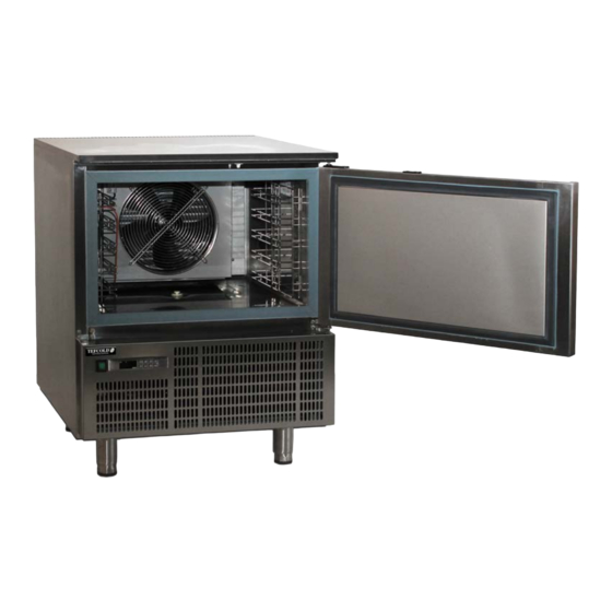
Depending on requirements, the appliance is produced in several versions. BLC3 BLAST CHILLER/FREEZER Model suitable to contain 3 trays with blast chilling capacity of 12kg and 8 kg in shock freezing. -
Page 8: Safety
2. SAFETY It is recommended to carefully read the instructions and warnings contained in this manual before using the appliance. The information contained in the manual is fundamental for the safety of use and for machine maintenance. Keep this manual carefully so that it can be Consulted when necessary. The electric plant has been designed in compliance with the IEC EN 60335-2-89 and EN 60335-1 standard. -
Page 9: Recommendations For Use
avoiding inflammable products or those that contain substances that are harmful to personal health. In the case of prolonged inactivity, as well as disconnecting all the supply lines, it is necessary to accurately clean all internal and external parts of the appliance. 3.RECOMMENDATIONS FOR USE Prolonged Inactivity If the appliance remains inactive for a long period, proceed as follows... -
Page 10: Blast Chilling Cycle
After blast chilling/shock freezing the product, it can be stored in a preservation cabinet after having been duly protected .A tag should be applied describing the contents of the product, blast chilling/shock freezing date and expiry date. When the product has been blast chilled it must be preserved at a constant +2℃... -
Page 11: Cleaning And Maintenance
4.CLEANING AND MAINTENANCE 4.1 Recommendations for Cleaning and Maintenance Activate all envisioned safety devices before carrying out any maintenance interventions, In particular, deactivate the electrical power supply using the automatic isolating switch. 4.2 Routine Maintenance Routine maintenance consists of daily cleaning of all the parts which can into contact with foodstuffs and the periodic maintenance of the burners, nozzles and draining pipes. - Page 12 As the fins of the evaporator are very sharp. always wear protective gloves for the next phases .Only a brush must be used for cleaning :do not use jets of liquid or sharp instruments. To access the evaporator proceed as follows: Open the door(A) of the appliance.
-
Page 13: Trouble Shooting
5.TROUBLE SHOOTING The information shown below aims to help with the identification and correction of any anomalies and malfunctions which could occur during use. Some of these problems can be resolved by the user. For the others, precise skill is required and they must therefore only be carried out by qualified staff. Problem Causes Solutions... -
Page 14: Installation
6. INSTALLATION 6.1 Packing And Unpacking Handle and install the appliance respecting the information provided by the manufacturer, shown directly on the packaging, on the appliance and in this manual. The lifting and transportation system of the packaged product envisions the use of a fork-lift truck or a pallet stacker. -
Page 15: Electric Power Supply Connection
temperature can compromise its performance and, in more serious cases, cause the appliance’s protections to start up. Therefore, consider the most critical room conditions that can be reached in that position before making a choice. Level the appliance by acting on the individual feet. This appliance can only be installed and operate in rooms which are permanently ventilated, in order to guarantee correct operation. -
Page 16: Dispoal Of The Appliance
7.DISPOAL OF THE APPLIANCE This appliance is marked in compliance with the 2002/96/EC European Directive. WASTE ELECTRICAL AND ELECTRIC EQUIPMENT (WEEE). By assuring that this product is disposed of correctly, the user contributes to preventing the potential negative consequences on the environment and health. symbol found on the product or on the accompanying documentation indicates that this product must not be treated as domestic waste but must be taken to suitable collection points for the recycling of electric and electronic appliances. -
Page 17: Xb570L Blast Chill&Freeezer Controller
XB570L BLAST CHILL&FREEEZER CONTROLLER 9. General Features The series XB has been created for fast chilling or freezing goods according to international food safety standards. There are FOUR types of cycles: The CYCLES: Cy1, Cy2, Cy3, Cy4 are pre-set according to the most common cycles used in food - safety applications;... -
Page 18: Probes Connection
11.1 PROBES CONNECTION The probes shall be mounted with the bulb upwards to prevent damages due to casual liquid infiltration. It is recommended to place the thermostat probe away from air streams to correctly measure the average room temperature. Place the defrost termination probe among the evaporator fins in the coldest place, where most ice is formed, far from heaters and from the warmest place during defrost, to prevent premature defrost termination. -
Page 19: Keyboard In Stand-By
14.2 KEYBOARD IN STAND-BY HOW TO SELECT A CYCLE: Push and release the (3) key till the desired cycle is selected. HOW TO START A CYCLE: Push and release the START/STOP button (2). Il The correspondent yellow LED is switched on.. HOW TO TEMPORARILY STOP THE RUNNING CYCLE. -
Page 20: Keyboard When A Cycle 1,2,3,4 Is Running
HOW MODIFY A CYCLE: 1. Push the key (6) for several seconds till the first parameter (CyS) is displayed. 2. Use the UP and DOWN keys to browse the parameters. 3. To modify a parameter push the SET key and use the arrow keys. 5. -
Page 21: Keyboard When The Holding Cycle Is Running (H)
14.4 KEYBOARD WHEN THE HOLDING CYCLE IS RUNNING (H) HOW TO DISPLAY THE HOLDING (REGULATION) SET POINT While the holding cycle is running, (H icon lighted), push the SET key and the holding set point is displayed on the UPPER display while the SETH label on the bottom display HOW TO MODIFY THE ROOM SET POINT... -
Page 22: How To Start A Manual Defrost
14.6 HOW TO START A MANUAL DEFROST Assure that none cycle is active or the hold mode is running. 1. Hold press the UP key fro few seconds. NOTE: The defrost will not be done if the temperature detected by the evaporator probe is higher than EdF (stop defrost temperature) parameter. -
Page 23: How To Select A Cycle
15. How To Select A Cycle 1. Push the to move among the cycles C1, C2, C3, C4 and the holding cycle. The related symbol on the display will be lighted and the cycle will be selected. NOTE: to pass from a cycle to another one simply push the key when the controller is in stand–by mode. -
Page 24: Probes
the beginning of the current phase. Con Compressor ON time with faulty probe: (0÷ 255 min) time during which the compressor is active in case of faulty thermostat probe. With COn=0 compressor is always OFF COF Compressor OFF time with faulty probe: (0÷255 min) time during which the compressor is off in case of faulty thermostat probe. -
Page 25: Auxiliary Relay Configuration
alarm signalling: the flashing message “dA” is displayed. If doA=nu the door alarm will be not signalled. dLc Stop count down of the running cycle with door open y = count down is stopped with door openi; n= count down goes on with door open; rrd Regulation restart with door open alarm: y = count down and regualtion restart when door open alarm is signalled.;... -
Page 26: Auxiliary Relay Management
ES. OAS=0 the set point of the second compressor s the same set point of the first compressor. OAS=5 the set point of the second compressor is SET (of first compressor) + 5; OAS=-5 the set point of the second compressor is SET (of first compressor) - 5; OAH Differential for second compressor: (-12.0÷12,0;... -
Page 27: Temperature Alarms
Cn= runs in parallel with compressors, OFF during defrost; o-Y = continuous mode, on during defrost; C1y= runs in parallel with the first compressor, on during defrost; C2y= runs in parallel with the second compressor, on during defrost; Cy= runs in parallel with compressors, on during defrost; FSt Fan stop temperature: (-50÷50°C/°F;... -
Page 28: Configurable Cycle Parameters
• soft chill • freezing cycle 2. For each phase there are 3 parameters. iS1, (iS 2, iS 3): Set point related to the insert probes that stops the current phase. rS1, (rS2, rS3): set point of the room temperature for each phase. Pd1, (Pd2, Pd3): the maximum duration time for each phase. - Page 29 17.3.1 First phase: “Hard chill”. It is normally used to fast chill hot foods. E.g. from 80°C / 170°F to 20°C / 70°F During “Hard Chill”, both compressor and fan are always on until the rS1 temperature is reached. At this point compressor is turned on end off so as to keep the temperature of the room at the rS1 value.
-
Page 30: Installation And Mounting
instrument keep on working, but the alarm message “OCF” is given. 18. Installation and mounting Instruments XB570L shall be mounted on vertical panel, in a 150x31 mm hole, and fixed using two screws ø 3 x 2mm. To obtain an IP65 protection grade use the front panel rubber gasket (mod. RG-L). The temperature range allowed for correct operation is 0 - 60 °C. -
Page 31: Xb07Pr - Printer (Optional)
19. XB07PR - Printer (optional) The XB570L is designed to work with the XB07PR. The XB07PR kit is composed by: 1. Printer 2. Power adapter 3. Connecting cables 19.1 PRINTER DIMENSIONS 19.2 PRINTER MOUNTING SCREW FIXING PANEL CUT OUT... -
Page 32: Connection To The Xb570L - Xb07Pr
19.3 CONNECTION TO THE XB570L – XB07PR 20. Electrical connections The instruments are provided with screw terminal block to connect cables with a cross section up to 2,5 mm2 for the digital and analogue inputs. Relays and power supply have a Fast on connection (6,3mm). Heat resistant cables have to be used. -
Page 33: Upload (From The Instrument To The "Hot Key")
2. Automatically the parameter list of the “Hot Key” is downloaded into the Wing memory, the “DoL” message is blinking. After 10 seconds the instrument will restart working with the new parameters. 3. Turn OFF the instrument remove the “Hot Key”, plug in the TTL serial cable, then turn it ON again. At the end of the data transfer phase the instrument displays the following messages: “end “... -
Page 34: Technical Data
24. Technical data Housing: self extinguishing ABS. Case: frontal 185x38 mm; depth 70mm; Mounting: panel mounting in a 150x31mm panel cut-out Frontal protection: IP65 Connections: Screw terminal block £ 2,5mm² wiring. Power supply: 230Vac, ±10% Power absorption: 5VA max. Display: dual display Inputs: 5 PTC or NTC probes Relay outputs: compressor: relay SPST 20(8)A or 8(3) A, 250Vac... -
Page 35: Standard Values Of The Parameters
Cy3: direct fast freezing with holding CyS = tEP iS2=-18°C Pd3 = 4 dbC = no rS2=-28°C dbH = yes HdS = -21°C iS1 = -18°C Pd2 =OFF rS1=-30°C iS3 =-18°C Pd1 = 4.0 rS3=-28°C Cy4: direct fast freezing without holding CyS = tEP iS2=-18°C Pd3 = OFF... - Page 36 Description Values Level Second digital input polarity Time delay for digital input alarm First configurable relay function Second configurable relay function Third configurable relay function Compressor setting during the holding Second compressor switching on delay Set point for second compressor OAH Differential for second compressor Probe selection for second compressor Auxiliary output timer...
Need help?
Do you have a question about the BLC3 and is the answer not in the manual?
Questions and answers