
Subscribe to Our Youtube Channel
Related Manuals for Strebel S-WG 100


Summary of Contents for Strebel S-WG 100
- Page 1 STREBEL S-WG 80 - 100 - 120 - 150 - 180 Wall hung high efficiency water heater Installation, Operating and Maintenance Manual 2015-05-06 v2.1...
-
Page 2: Table Of Contents
TABLE OF CONTENTS INTRODUCTION ……………………….………………………......................5 SAFETY GUIDELINES ................................. 5 ..................................5 ENERAL ......................6 MPORTANT TECHNICAL WARNINGS AND GUIDELINES TECHNICAL DATA S-WG WATER HEATERS .......................... 10 DIMENSIONS ..................................... 12 S-WG80 – S-WG120 ........................12 ATER HEATERS S-WG150 S-WG180........................13 ATER HEATERS S-WG ................................ - Page 3 10 USER INTERFACE ..................................58 10.1 ........................... 58 ONTROL PANEL ISPLAY UNIT 10.2 ..........................59 ONTROL PANEL MENU STRUCTURE 10.3 ............................60 ISPLAY DURING OPERATION 10.4 ..............................61 ONITOR SCREENS 10.5 ..............................63 ERVICE FUNCTION 10.6 ..............................64 WEEPER FUNCTION 10.7 ..........................
-
Page 4: Introduction
INTRODUCTION This manual is written for: the installer system design engineer the service engineer abbreviations NOTICE symbols Warning: important information related to the safety of persons and/or the appliance terminology Flow Water heater hot water out Return Water heater cold water in SAFETY GUIDELINES General... -
Page 5: Important Technical Warnings And Guidelines
For a given combination of water heaters and tanks, pump choice is very important with respect to the re- quired flow velocity. STREBEL has done the calculations and provides a number of tables in which you can find the right pump type suitable for your particular installation. - Page 6 Warnings and guidelines (continuation) STREBEL is not liable for any damage caused by inaccurately following these mounting instructions. Only STREBEL parts may be used when carrying out any repair or service works. Do not use chlorine based products for brazing.
- Page 7 Part number S-WG 80 27112 Prescor B ¾ - 10 bar - 150 kW E04.015.090 S-WG 100 27112 Prescor B ¾ - 10 bar - 150 kW E04.015.090 S-WG 120 27112 Prescor B ¾ - 10 bar - 150 kW E04.015.090...
- Page 8 FILTER PUMP NON RETURN VALVE INLET COMBINATION - Overflow VALVE - Controllable return valve - Valve SAFETY VALVE PRESSURE REGULATING VALVE AUTOMATIC VENT Cold water inlet Hot water circulation flow Circulation flow return Pressure relief valve (mandatory in case service water pressure is too high) Inlet combination with valve (mandatory) Apply filter if necessary (recommended) A suitable safety valve must be mounted near the water heater (mandatory)
-
Page 9: Technical Data S-Wg Water Heaters
TECHNICAL DATA S-WG WATER HEATERS GENERAL Product Identification number CE 0063 BR3190 Classification II2H3P Gas Appliance Type B23; B23P; C13X, C23X, C33X, C43X, C53X, C63X, C83X Type water heater S-WG80 S-WG100 S-WG120 S-WG150 S-WG180 Dimensions (h x w x d) 842 x 476 x 486 898 x 476 x 677 Water content est. - Page 10 The S-WG water heater is standard set for Natural gas G20 Gases used must meet the European standard EN 437. Water heater control includes the next programmable features: Cascade control for up to twelve water heaters Remote operation and heat demand indication from each water heater ...
-
Page 11: Dimensions
DIMENSIONS Water heaters S-WG80 – S-WG120 TWIN PIPE CONCENTRIC twin pipe concentric Connections (mm/ ” ) WG80 WG100 WG120 WG80 WG100 WG120 flue gas Ø80 Ø100 Ø80 Ø100 air inlet Ø80 Ø100 Ø125 Ø150 R 1½” R 2” R 1½” cold water R 2”... -
Page 12: Water Heaters S-Wg150 And S-Wg180
Water heaters S-WG150 and S-WG180 TWIN PIPE CONCENTRIC twin pipe concentric Connections (mm/ ” ) S-WG 150 -180 S-WG 150 -180 flue gas Ø130 Ø100 air inlet Ø130 Ø150 Rp 2” Rp 2” cold water inlet (swivel) (swivel) Rp 2” Rp 2”... -
Page 13: S-Wg Tanks
S-WG tanks 300 Ltr. 450 Ltr. E09.012.246 Manual S-WG... - Page 14 750 Ltr. E09.012.246 Manual S-WG...
-
Page 15: Cascade Frames S-Wg80 - S-Wg180
Cascade frames S-WG80 – S-WG180 Frames for two, three and four water heaters S-WG80 up to S-WG180 E09.012.246 Manual S-WG... - Page 16 E09.012.246 Manual S-WG...
-
Page 17: Accessories And Unpacking
(80/125→80-80) S-WG 80 water heater: Conversion set for parallel to concentric flue-air terminal E61.001.170 (80-80→80/125) S-WG 100 - 120 water heater: Conversion set for concentric to parallel flue and air terminal E61.001.164 (100/150→100-100) S-WG 100 - 120 water heater: Conversion set for parallel to concentric flue-air termi- E61.001.171... -
Page 18: Installation Of The S-Wg
INSTALLATION OF THE S-WG General notes At every side of the water heater at least 50 mm of clearance should be applied to walls or wall units, 350 mm above the top side of the water heater and 250 mm from the bottom of the water heater. The installation area/room must have the following provisions: ... -
Page 19: Mounting The Water Heater And Tank
Mounting the water heater and tank 5.2.1 ATER HEATER MOUNTING Before mounting and installing the water heater the following connections should be considered: Flue gas system and the flue gas pipe connections Air supply system and connections ‘Cold in’... -
Page 20: Tank Positioning
Detailed drawing of the water heater mounting and the fixation of the locking plate. 5.2.2 ANK POSITIONING The tank can be placed at will* on a stable floor, but not too far from the water heater(s). See § 9.4.3, ‘Intercon- necting pipes –... -
Page 21: Flue Gas And Air Supply System
FLUE GAS AND AIR SUPPLY SYSTEM General The water heater has a positive pressure flue system. The available combined pressure drop for the inlet and outlet system, for a single water heater, is 200 Pa for the complete water heater range. For a multiple water heater installation, always contact the manufacturer for advice. -
Page 22: Flue System Classification B23P
Height A This is the height of the air inlet. A rain hood should pre- vent rainwater entering the air supply system. When the inlet and outlet are mounted on a flat roof, the inlet should be at least 60 cm above the roof surface and at least 30 cm above the maximum snow level. -
Page 23: Combustion Air Quality
Combustion air quality Combustion air must be free of contaminants. For example: chlorine, ammonia and/or alkali agents, dust, sand and pollen. Remind that installing a water heater near a swimming pool, a washing machine, laundry or chemical plants does expose combustion air to these contaminants. Flue gas &... - Page 24 Flue gas and air supply resistance table NOTICE: This table can only be used for a single flue/air system for one water heater. Do NOT use this table for common flue/air systems with cascaded water heaters. FLUE GAS PIPING RESISTANCE [Pa] FLUE GAS OUTLET Ø...
- Page 25 A: Twin pipe system with separate pipes for flue gas and air supply. Example A Water heater type: S-WG 180 Diameter: 130 mm. Number Pa total Straight tube m¹ total Bend 90° Flue outlet conical Total resistance flue gas outlet: 66.9 Diameter: 130 mm.
- Page 26 B: Twin pipe system with separate pipes and concentric roof terminal. Example B Water heater type: S-WG 120 Diameter: 100 mm. Number Pa total Straight tube m¹ total Bend 90° concentric Roof terminal 150/100 Adaptor conc./par. 150/100 Total resistance flue gas outlet: Diameter: 100 mm.
- Page 27 C: Single pipe for flue gas outlet only (air supply from plant room). Example C Water heater type: S-WG 100 Diameter: 100 mm. Number Pa total Straight tube m¹ total Bend 90° Bend 45° Flue outlet H/D = 1.0 15.2 15.2...
- Page 28 Twin pipe system: flue gas and air supply positions. Concentric roof terminal concentric/parallel adaptor Flue outlet Air inlet Example B Example A Example A water heater type S-WG80 S-WG100 S-WG120 S-WG150 S-WG180 Diameter air inlet Diameter flue outlet Diameter roof terminals Maximum pipe length 18.0 31.5...
- Page 29 Single pipe system: flue gas positions: Flue outlet Air inlet Vented area Example C Example C water heater type S-WG80 S-WG100 S-WG120 S-WG150 S-WG180 Diameter air inlet Diameter flue outlet Diam. roof terminal Maximum pipe length 21.5 46.5 27.5 49.5 30.0 (total outlet length)
- Page 30 Concentric pipe system: flue gas positions: Concentric roof terminal Concentric wall terminal Example E Example D Example D water heater type S-WG80 S-WG100 S-WG120 S-WG150 WG180 Diameter concentric pipe 80/125 100/150 100/150 Concentric roof terminal 80/125 100/150 100/150 RECOMMENDED (choose B, C or E) Maximum pipe length 14.5...
-
Page 31: Electrical Installation
ELECTRICAL INSTALLATION General All the wiring is connected to a separate connector that is fitted in a socket. The connector can be taken from the sockets without loosening the wiring. The connections are placed on top of the display panel and can be ac- cessed by removing the water heater front door and the connector protection cover. -
Page 32: Sensor Values
11-12 EXTERNAL WATER PRESSURE SWITCH A water pressure switch is mounted in the water heater. As an option an external water pressure switch can be wired to the terminals. In this case remove connectors from ‘internal water pressure switch’. When terminals 11-12 are not bridged, the water heater will lock-out. -
Page 33: Electrical Schematics
Electrical schematics E09.012.246 Manual S-WG... - Page 34 E09.012.246 Manual S-WG...
-
Page 35: The S-Wg Water Heater
THE S-WG WATER HEATER Water quality In direct water heating appliances the water flows directly through the heat exchanger of the water heater. Because all the time fresh water, containing dissolved minerals, is heated, sca- ling may occur. To prevent this, water quality must meet a number of standards. The values are the following: Water temperature max. -
Page 36: Flow Monitoring
Again F16, display ‘FlowReturn dt fault’. NB! All values of this flow monitoring have been programmed by STREBEL in order to get the best performance combined with a long life time. -
Page 37: The S-Wg Sanitairy System: Installation Instructions
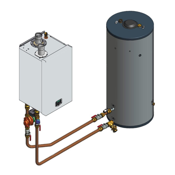
THE S-WG SANITAIRY SYSTEM: INSTALLATION INSTRUCTIONS The S-WG system The system as a whole is set up as shown in the next two examples, the first showing a combination of one wa- ter heater and one tank, the second showing a combination of three water heaters and two tanks. Other combi- nations are possible as well. -
Page 38: Cascade Set-Up
9.1.2 ASCADE SET S-WG water heaters and tanks can be installed cascaded in a number of possible combinations cf. the instruc- tions in the next paragraphs. For the installation of cascaded water heaters and tanks, always consult the tables in § 9.4. All re- quirements concerning pipe diameters and lengths as well as pump choice are presented orderly here. - Page 39 For large capacity installations (more than two water heaters) consult STREBEL. E09.012.246 Manual S-WG...
-
Page 40: Control General
9.1.3 ONTROL GENERAL There is no need for a sensor in the tank, because when the pump starts to run, the inlet sensor of the water heater is measuring the water temperature of the tank. When there is no drawing water from the tank, the inlet sensor is measuring the water temperature in the tank. -
Page 41: Water Heater And Tank: Connections And Connection Sizes
Water heater and tank: connections and connection sizes 9.2.1 ONNECTING THE TANK TO THE WATER HEATER Connect the pump by means of couplings and a piece of copper pipe to connection A of the water heater (note the flow direction of the pump). ... -
Page 42: To Connect The Tank To Your Dhw Installation
Connect the recirculation line to connection F, labelled ‘circulation return’, on the side of the tank, at the same height as inlet C. The STREBEL tanks have the following DHW connections: COLD IN for inlet of fresh water ... -
Page 43: Condensate Drain Connection
9.2.3 ONDENSATE DRAIN CONNECTION The condensate drain is placed at the centre at the bottom of the water heater and has a ¾ inch hose discharge. Connect this flexible hose to the sewer system. Use only plastic parts with the condensate drain. Metal lines are not allowed. Blockage of this drain might damage the water heater. -
Page 44: Cascade Systems: Assigning Pipe Codes
Cascade systems: assigning pipe codes With the tables in § 9.4 (from page 47 onwards) the diameters of the several connection pipes can be assessed, so that there will always be sufficient flow. For using the tables in a straightforward manner, water heaters and pipes need to be numbered, where water heater-1 is the one that‘s situated the furthest away from the tanks. -
Page 45: Pipe Codes At The Tanks Side
SUMMARY ENCODING PIPES WATER HEATER SIDE: Assigning codes to a one water heater installation: There’s only one flow pipe, encoded FF, and one return pipe, encoded RR. For the right diam- eters see § 9.4.1, pick the table of the corresponding water heater type. Assigning codes to cascades: two or more water heaters to connect: First number the water heaters: water heater-1 is the one that‘s situated the furthest away from the tank(s). -
Page 46: Connection Component Tables - Diameters And Lengths
Connection component tables – diameters and lengths General remark: diameters may at any time be chosen LARGER than specified in the tables, but never SMALLER. Flow must remain guaranteed. The pipe tables in this section are numbered after capacity: Water heater tables WH-80, WH-100 etc. up to WH-180 and tank headers T-80, T-100 etc. up to T-180. 9.4.1 ATER MANIFOLDS Numbering:... -
Page 47: Tank Headers
(Water manifolds continued (§ 9.4.1)) S-WG150 Nr. of cascaded FF/RR F1/R1 F2/R2 F3/R3 F4/R4 F5/R5 F6/R6 F7/R7 water heaters 541.5 802.1 541.5 932.3 541.5 802.1 1062.5 541.5 802.1 932.3 1332.8 541.5 802.1 932.3 1062.5 1332.8 541.5 802.1 932.3 1062.5 1332.8 1593.0 541.5 802.1... - Page 48 (Tank headers continued (§ 9.4.2)) S-WG120 Pipe diameter A1/B1 to the water tanks Nr. of cascaded 1 tank 2 tanks 3 tanks 4 tanks 5 tanks 6 tanks 7 tanks 8 tanks water heaters 541.5 421.4 351.3 281,2 281.2 221.1 221.1 221.1 802.1...
-
Page 49: Interconnecting Pipes - Diameters And Equivalent Length
– 9.4.3 NTERCONNECTING PIPES DIAMETERS AND EQUIVALENT LENGTH When the water heaters and tanks are separated over some distance, the interconnecting pipes may only have a certain maximum length, dependent of the number of bends and the like components. For every applied compo- nent a so-called ‘equivalent length’... -
Page 50: Pump Choice And Pump Control
Pump choice and pump control Pump choice is of very great importance, because, in combination with the system’s total resistance, it sets the water velocity in water heater and pipes. The right water velocity is essential for correct functioning and a long life time of the system. -
Page 51: Nominal Flow Per Water Heater Type
The applied pump must be controlled by the S-WG water heater control. If, for any reason, an external pump control is applied without written approval of STREBEL, then the complete warranty on the S-WG water heater and all delivered parts will become invalid. -
Page 52: Pump: Maximum Electrical Power
Directly connect the pump to the mains of the water heater and use the cable kit from STREBEL. Control connections of an EC pump can be established in several ways, set by parameter P5BN. -
Page 53: Elaborated Examples
Elaborated examples To work out the examples in this section, the rules of page 46 are given again: 1. Assigning codes to a one water heater installation: There’s only one flow pipe, encoded FF, and one return pipe, encoded RR. For the right diameters see §... -
Page 54: Two S-Wg100 Water Heaters With Two 450-Litres Tanks
9.6.2 S-WG100 450- WATER HEATERS WITH TWO LITRES TANKS Example 2 COLD IN KOUD IN 2 boilers S-WG100 2 tanks 450 L B1 A1 B1 A1 Water heater connections, assigning codes: For this system rule 2 must be applied. Number the water heaters: water heater-1 is the water heater furthest from the tank(s), see picture. Number de connection pipes directly connected to the water heaters: F1 en R1, see picture. -
Page 55: Three S-Wg180 Water Heaters With Five 750-Litres Tanks
9.6.3 S-WG180 750- HREE WATER HEATERS WITH FIVE LITRES TANKS Example 3 3 ketels S-WG180 tanks COLD IN KOUD IN 5 tanks 750 L B1 A1 B1 A1 B1 A1 Water heater connections, assigning codes: For this system rule 2 must be applied. Number the water heaters: water heater-1 is the water heater furthest from the tank(s), see picture. - Page 56 So for this system, sizes of at least 541.5 [mmmm] are to be applied for all pipes directly connected to the water heaters and tanks, and pipes sized at least 1062.5 [mmmm] for the flow and return connections be- tween the cascaded water heaters and the tanks. The pipes F2 and R2 must be at least 932.3 [mmmm]. = 54 x 1.5 = 93 x 2.3 = 106 x 2.5...
-
Page 57: User Interface
USER INTERFACE 10.1 Control panel / Display unit DISPLAY 2 rows / each 20 characters ON/OFF MENU RESET ENTER COMM. PORT SERVICE Press and hold for 6 seconds to switch water heater on/off. ON/OFF Is also used as RESET button and ENTER button when pro- RESET ENTER gramming. -
Page 58: Control Panel Menu Structure
10.2 Control panel menu structure BASE SCREEN : (appears during operation) CONFIRMATION CHANGE WTRHTR : No demand / Standby / burning When changes are being made in the menus within this dashed rectangle, > > > : 1 1 8 ° C ( 1 2 5 ° C ) the user presses ENTER to confirm the changes. -
Page 59: Display During Operation
10.3 Display during operation During normal operation the text in the display shows the status of the water heater. In the following graphs the several displays during normal operation are explained. Display at WATER HEATER / HOT WATER DEMAND Heat demand type: Actual status: W A T R H T R : S T A N D - B Y... -
Page 60: Monitor Screens
10.4 Monitor screens During normal operation and standby, the “◄” and “►” buttons can be used to show some water heater informa- tion, including measured temperatures, settings and data. In the following graphs is explained which values can be shown in the display. When no button is activated for three minutes, the display will return to its status dis- play. - Page 61 SCREEN: 11 C a s c D e s i g n 0 = MASTER, 1 ..11 = SLAVES C a s I n f 0 1 2 3 4 5 6 7 8 9 A B Displays number, priority and state of cascade water heaters. DESCRIPTION "CASCINFO"...
-
Page 62: Service Function
10.5 Service function The following graphs describe how to use the service function. Operating screen: W A T R H T R : S T A N D - B Y > > > : 1 2 3 . 4 ° C ( 1 2 3 . 4 ° C ) Press [SERVICE] and hold for 3 seconds. -
Page 63: Sweeper Function
10.6 Schornsteinfeger function The purpose of this function is to have an easy interface for the "Schornsteinfegers" in Germany, to be able to do their required testing on the water heater. This is a simplified function similar to the normal service function of the water heater. When the "Schornsteinfeger"... -
Page 64: Programming In Standby Mode
10.7 Programming in standby mode Standby Use the standby mode for modifying water heater settings without interaction with the water heater control. Changes are effectuated by leaving standby mode. Properties of standby mode: Keys are active and the menu is accessible. ... -
Page 65: Set Points
10.9 Set points The following graphs describe how to program the hot water set points. Heating set point normal/day time: (parameter P4 AA = 1/2) D H W s e t p o i n t ° C This is the water temperature set point that is active during the programmed DHW periods (parameter P4 AA = 1/2) DHW set point reduction: (parameter P4 AA = 1/2) D H W... -
Page 66: 10.10 Setting The Timer Programs
10.10 Setting the timer programs Two different programs can be set with the water heater, these are: DHW program Anti-legionnaires’ disease (pasteurisation) program START PROGRAMMING Three programmed periods each day can be set (period 1, 2 and 3). During this period the unit will use the normal DHW set point. - Page 67 HOT WATER PROGRAM > > > From previous page < < < Setting DHW program times: P r o g r a m D H W M o n Press [►] to browse through the values that can be set at the bottom line. The blinking value can be changed.
- Page 68 ANTI LEGIONNAIRES’ DISEASE PROGRAM See the following description. The standard factory setting for this function is “OFF”. > > > From previous page with HOT WATER part < < < Setting legionella program (day and time): P r o g r a m L e g i o n e M o n...
-
Page 69: 10.11 Checking The Operating History
10.11 Checking the operating history The following graphs describe how to check the operating history of the water heater. Operating screen: W A T R H T R : S T A N D - B Y > > > : 1 2 3 . 4 ° C 1 2 3 . -
Page 70: 10.12 Checking The Fault History
10.12 Checking the fault history The following graphs describe how to check the fault history of the water heater. Operating screen: W A T R H T R : S T A N D - B Y > > > : 1 2 3 . 4 ° C ( 1 2 3 . 4 ° C ) Press [MENU] Select "Faulthist"... -
Page 71: 10.13 Setting The Maintenance Specifications
10.13 Setting the maintenance specifications MAINTENANCE SETTINGS The unit can be programmed in such a way that an automatic maintenance message is displayed. There are three options that can be selected. A maintenance message appears after: * A programmed date is reached. * An amount of burning hours is reached. - Page 72 From previous page Screen: Selecting message at certain date. M a i n t e n M o d e D a t e Press [►] to set: The date for the maintenance message. Press [◄] to: Return to maintenance mode selection. Press [►] to browse through the values that can be set at the bottom line.
- Page 73 From previous page Screen: Message after total amount of burning hours. M a i n t e n M o d e B u r n i n g h o u r s Press [►] to set: The total amount of burning hours for the maintenance message. Press [◄] to: Return to maintenance mode selection.
-
Page 74: 10.14 Setting The User Lock
10.14 Setting the user lock The following graphs describe how to activate the user lock of the display. The standard factory setting for this function is “OFF”. The "USER LOCK" menu. In this menu the water heater can be locked for (end-)users. 0 = UNLOCKED 1 = LOCKED When the water heater is unlocked, the user can enter the... -
Page 75: 10.15 Setting The Parameters With The Display Menu
10.15 Setting the parameters with the display menu The functions of the controller are embedded in de electronics. The values and settings that are being used for these controlling functions can be changed by programming these values. This can be done by a skilled and trained service engineer with the help of a computer, the correct software and an interface cable. - Page 76 The following graphs describe how to program the parameters by using the display: Operating screen: W A T R H T R : S T A N D - B Y The screen texts on these pages are standard part of the software and >...
- Page 77 Menu A: Heating c O f ° C The screen texts on these pages are Select the cascaded boilers supply temperature control. standard part of the software and This parameter is the offset of the selected CH apply to CH systems (boilers) and/or supply temperature of EACH boiler of the total cascade.
- Page 78 Menu B: Hot water D H i L O t i m e M i n Hot water function of the boiler. This parameter is the selectable time period after which the boiler switches The screen texts on these pages are from LOW to HIGH set point with an indirect hot water standard part of the software and demand.
- Page 79 Menu B: Hot water D H d s c D i ° C Function for the direct hot water boiler. This parameter is the hysteresis of the selected The screen texts on these pages are HW temperature of the boiler. standard part of the software and apply to CH systems (boilers) and/or Menu B: Hot water...
- Page 80 Menu C: Cascade B u s a d r e s s Function for the cascading of the boiler(s). The screen texts on these pages are This parameter determines the address of the boiler standard part of the software and for the total cascading control.
- Page 81 Menu D: General 1 0 V c o n Function for the external control of the boiler by using The screen texts on these a 0-10 Volt signal (Connections 15-16). pages are standard part of the 0 = No external control software and apply to CH sys- 1 = Control based on temperature setting tems (boilers) and/or DHW...
- Page 82 Menu D: General c o n f i g Function for the setting of the water pressure. Up to 4 bar a sensor is used, up to 6 bar a switch. The screen texts on these 0 = off pages are standard part of 1 = sensor the software and apply to CH 2 = switch...
-
Page 83: 10.16 Fault Codes Display
10.16 Fault codes display The following graphs describe the lock out codes of the water heater. A lock out code can only be removed by a manual reset of the water heater. NOTICE: Before resetting the water heater always check the water heater, DHW system and all components corresponding to the related lock out description. - Page 84 Display message a m e p u m p 9 9 9 Reason Flame detected during normal operation, but was lost while running. Display message a m e g n a p u m p 9 9 9 Reason Flame signal is detected while it cannot be expected. Display message F a n s p e e d...
-
Page 85: Blocking Codes
The following graphs describe the blocking codes of the water heater. A blocking code is only a temporary block- ing of the water heater, because of an extraordinary situation. The water heater will continue to operate after stabilisation of this situation. 10.16.2 LOCKING CODES The display is not blinking, but is lightened up during the blocking period. - Page 86 Display message Reason Water pressure is too low or too high. Display message Reason Outdoor temperature has exceeded the blocking temperature which is set in the pa- rameters. Display message Reason Temperature difference between flow and return exceeds the blocking value but not the lock out value.
-
Page 87: Messages
10.16.3 ESSAGES The following graphs describe the messages at the water heater display. Depending on the selected and acti- vated options for the water heater, it is possible that some messages will show up at the display of the water heater. -
Page 88: Controlling Options And Settings
CONTROLLING OPTIONS AND SETTINGS 11.1 Water heater options 11.1.1 0-10 VDC REMOTE FLOW TEMPERATURE SET POINT The hot water temperature is controlled by connecting an external 0-10 VDC signal to the water heater (connec- tions 15-16). P5BB Analogue input Config (0=off 1=temp) (display D1). This parameter must be set at "1"... -
Page 89: Anti-Legionnaires' Disease (Pasteurisation) Function
’ 11.1.2 ANTI EGIONNAIRES DISEASE PASTEURISATION FUNCTION To prevent Legionnaires’ disease, the water heater (software) provides a function for heating up the hot water storage tank (once a week or every day) to a higher water temperature than the normal active hot water set point. -
Page 90: General
11.2 General The following sections describe some general functions of the water heater and their possible use. 11.2.1 AX COOLING TIME The fan will cool down the heat exchanger according to the temperature settings (parameters) of the software. With this cooling parameter the maximum run time of the fan can be programmed. P2LK Max cooling time (display D4) [min.]... -
Page 91: Soft Start Option
11.2.4 OFT START OPTION Start parameters can be modified to achieve better start behaviour, in case of noise or other difficulties. This is done by reducing the fan ramp-up speed. Two reduced settings are available (I and II). P4BE Soft start (0=normal, 1=reduced fan ramp-up speed (I), 2= reduced fan speed ramp-up (II)) (display D9). -
Page 92: Commissioning The Water Heater
COMMISSIONING THE WATER HEATER 12.1 First: flushing the water heater with water After installation of the water heater the first step, before commissioning, is to flush the water heater and the whole DHW installation with fresh water to remove pollution, debris and other materials that might cause a block- ing. - Page 93 By pressing the [SERVICE] button of the water heater, the water heater can be started without a heating de- mand. The water heater will start to fire and also the pump will start to run. Firing of the water heater without a water flow (but filled with water!) will cause the so called “boiling noises”.
-
Page 94: Starting The Water Heater
STARTING THE WATER HEATER 13.1 General Check the gas pressure available at the gas connection pipe of the water heater. Use the pressure nipple (3) of the gas safety valve for this measurement. The gas pressure for the water heater, to operate properly under the correct load, must be at least 20 mbar. -
Page 95: Adjusting And Setting The Burner
ADJUSTING AND SETTING THE BURNER Before carrying out any adjusting of the burner, carefully read this complete chapter. 14.1 Introduction The burner must always be adjusted in the next situations: - A new water heater is installed - As part of a service/maintenance check, in case the CO values turn out to be incorrect Adjustment procedures for situation A are described in §... -
Page 96: Setting Screws Gas Valve Sdrawings
Table 2 pre adjustment settings gas valve for BIC water heaters water number of turns open (counter clockwise) heater nat. gas G20 / G25 propane G31 butane G30 type S-WG 0.75 1.25 WG100 2.25 * 0.75 * WG120 2.25 * 0.75 * WG150 4.25 *... - Page 97 80 & 100 150 & 180 E09.012.246 Manual S-WG...
-
Page 98: Adjustment Actions General Scheme
14.1.3 DJUSTMENT ACTIONS GENERAL SCHEME General scheme for adjustment of the gas valve(s). Check this scheme for an overview. To complete all necessary adjustments in right order, follow case A or B top-down through the scheme (B in- volves a few extra steps (grey fields)): GENERAL SCHEME SETTING STEPS case A case B... -
Page 99: Adjusting In Case Of A New Water Heater, Or After Service (Case A)
14.2 Adjusting in case of a new water heater, or after service (case A) 14.2.1 ENERAL REMARK For all adjusting steps under A the following must be applied: as long as measured CO values differ less than 0.3% from the table values, no adjustment is necessary, because this deviation is typical for the process (O values: ±... -
Page 100: Checking And Adjusting At Minimum Load S-Wg120 / S-Wg150 / S-Wg180
14.3.5 S-WG120 / S-WG150 / S-WG180 HECKING AND ADJUSTING AT MINIMUM LOAD Adjusting these water heaters at minimum load in case B involves extra measurements, to get both valves bal- anced: Use the [▼] button to decrease the actual load of the service (percentage) to the minimum. The following screen will appear: Display message W A T R H T R : S e r v... -
Page 101: Adjusting Procedures
14.4 Adjusting procedures Procedures 1 and 2, referred to in the previous sections 14.2 and 14.3, are described here: Procedure 1: adjust at maximum load In case B (gas conversion or replacement of gas valve): consult § 14.3. before starting procedure 1 below. Carry out the next 4 steps: 1. -
Page 102: Putting The Water Heater Out Of Operation
PUTTING THE WATER HEATER OUT OF OPERATION It is recommended to have the water heater operational all year round to prevent any frost damage during the winter and/or rotating parts getting jammed during other times of the year (built in water heater safety features). OUT OF OPERATION: On/off function. -
Page 103: Fault Codes, Blocking Codes
FAULT CODES, BLOCKING CODES FAULT CODES IMPORTANT: To avoid electric shocks, disconnect electrical supply before performing troubleshoot- ing. To avoid burns, allow the unit to cool before performing troubleshooting. Be aware that a fault code is an indication that the unit or the system needs attention. When repeatedly having faults these should not be neglected. - Page 104 u r n T e m p Display message p u m p 9 9 9 h r s Reason: Maximum return temperature exceeds limit value. Cause: Systems that pre-heats the water heater return temperature too much/high. Corrective action: Reduce pre heat temperature of external heat source. Cause: The need for heat in the system suddenly drops causing hot return water to the water heater.
- Page 105 e m p t o o Display message p u m p 9 9 9 h r s Reason Flue gas temp. exceeded 3 times limitation value within a certain period. Cause: Heat exchanger polluted and not able to transfer enough heat to system water. Corrective action: Check and clean heat exchanger.
- Page 106 b u r n e r Display message p u m p 9 9 9 h r s Reason Water heater not operational after 4 starting attempts. Cause: No spark. Corrective action: Check the igniter/ignition electrode and replace/clean it if necessary. Check the state of the ceramic insulator.
- Page 107 a m e Display message p u m p 9 9 9 h r s Reason Flame signal lost during operation. Cause: Bad gas supply pressure. Corrective action: Be aware that the specified gas pressure must be met during all operation conditions. Check if all gas valves in the supply line are completely open.
- Page 108 a m e g n a Display message p u m p 9 9 9 h r s Reason Flame signal detected, while water heater should not fire for operation. Cause: The flame detection circuit detects a flame which is not supposed to be present. Corrective action: Check the ignition/ionisation electrode and make sure it is clean (or replace it).
- Page 109 Display message x o n F a u p u m p 9 9 9 h r s Reason: Heat exchanger fuse exceeded maximum value. Cause: The thermal fuse of the heat exchanger has opened permanently. Corrective action: Switch off the electrical power and gas supply and contact supplier. Display message o w R e u r n...
- Page 110 p h o n s w i Display message p u m p 9 9 9 h r s Reason: Siphon pressure switch detects high pressure in the flue/siphon system. Cause: There is too much resistance in the flue gas circuit causing high pressure in the heat ex- changer at the flue gas side.
-
Page 111: Blocking Codes
16.2 Blocking codes The display is not blinking, but is lightened up during the blocking period. The water heater is blocking an action, because of an extraordinary situation. This action will be con- tinued after eliminating the extraordinary situation. Display message e m p 9 9 9 h r s... - Page 112 Cause: There is no water in the unit while firing. Corrective action: This is an unlikely situation while all the safeties for checking the water presence didn't detect anything. Only a lot of air in the system/unit (under pressure) can cause the water pressure switch to switch while no water is present.
- Page 113 Display message p u m p 9 9 9 h r s Reason Bad power supply Cause: The supplied power does not comply with the specifications. Corrective action: Check if the power supply is connected correctly to the unit. Check the voltage and frequency (should be Life Neutral, Gnd > 230Vac/50Hz). Make sure there is no signal failing or voltage peaks in the power supply.
- Page 114 Display message C a s c a d e o c k 9 9 9 h r s Reason Connection failure with one of the water heaters of the cascade. Cause: The unit is programmed in such a way that none of the water heaters in a cascade will fire, if one has a lockout.
-
Page 115: Maintenance Attention Function
16.3 Maintenance attention function The display shows alternately the base screen and this message, while backlight is blinking. The water heater is operating, but will count the exceeding hours. A parameter must be changed, after service, to remove this message. Display message N e e d s e n a n... -
Page 116: Maintenance
MAINTENANCE 17.1 General For a good, safe and long-time operation of the water heater, it is advised to carry out maintenance and service at least every twelve months. Both safety and life time will thus be improved. Omission of preventive and correc- tive maintenance can have warranty consequences. -
Page 117: Inspection & Maintenance
17.3 Inspection & maintenance Inspection, maintenance and the replacement of water heater parts should only be done by a skilled service engineer. Apart from the maintenance proceedings it is advised to have a log chart for every water heater that describes the following aspects: ... - Page 118 Ignition / ionisation electrode When the complete burner is removed, it is also very easy to check the ignition electrode. First check if the dis- tances between the electrodes and between the electrode and the burner are according to the graph below. When these are not correct, try to bend the electrodes in the right position.
- Page 119 Heat exchanger and burner room After the removal of the complete burner unit, check if there is any debris and dirt in the heat exchanger. The coils of the heat exchanger can be cleaned by using a non-metallic brush. After this the dirt and dust can be removed with a vacuum cleaner and by flushing the burner room with water.
-
Page 120: User Instructions
USER INSTRUCTIONS After installing and commissioning of the water heater demonstrate the operation of the entire DHW system to the end-user. The user should be made familiar with all safety precautions of the water heater and the installa- tion. The user should be instructed that service and maintenance of the water heater is required every twelve months. -
Page 121: Index
INDEX 0-10 vdc remote flow temperature set point, 89 night shift, 66 accessories, 18 overpressure safety valve, 8 ff, 42 ff. accessories and unpacking, 18 adjusting and setting the burner, 96 password, 59, 76 air supply, 22 plant room, 20 air venting, 93 positioning the water heater, 20 anti-Legionnaires’... - Page 122 - notes - E09.012.246 Manual S-WG...
- Page 123 - notes - E09.012.246 Manual S-WG...
- Page 125 Strebel Ltd 1f Albany Park Industrial Estate, Frimley Road, Camberley, Surrey, GU16 7PB Tel: 01276 685422 Fax: 01276 685405 Email: info@strebel.co.uk Web: www.strebel.co.uk Further information on our complete product range is available from our website. CAST IRON – CONDENSING – STEEL SHELL – WATER HEATERS – RENEWABLES...
Need help?
Do you have a question about the S-WG 100 and is the answer not in the manual?
Questions and answers