Table of Contents
Advertisement
Quick Links
Advertisement
Table of Contents

Summary of Contents for Panasonic PV-GS80P
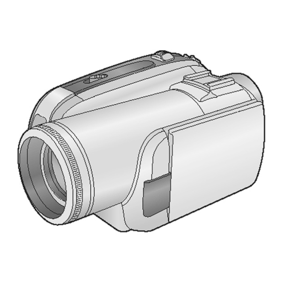
- Page 1 ORDER NO. MKE0701401CE Digital Video Camcorder PV-GS80P PV-GS83P PV-GS85P PV-GS80PC PV-GS85PC Vol. 1 Colours (S)....Silver Type © 2007 Panasonic Shikoku Electronics Co., Ltd. All rights reserved. Unauthorized copying distribution is a violation of law.
-
Page 2: Table Of Contents
PV-GS80P / PV-GS83P / PV-GS85P / PV-GS80PC / PV-GS85PC CONTENTS Page Page 1 Safety Precautions 9.1. Cleaning Lens, Viewfinder and LCD Panel 1.1. General Guidelines 9.2. How to use the DVC Head Cleaning Tape / VFK1451 2 Warning 10 Block Diagrams 2.1. -
Page 3: Safety Precautions
PV-GS80P / PV-GS83P / PV-GS85P / PV-GS80PC / PV-GS85PC 1 Safety Precautions 1.1. General Guidelines 1. IMPORTANT SAFETY NOTICE There are special components used in this equipment which are important for safety. These parts are marked by in the Schematic Diagrams, Circuit Board Layout, Exploded Views and Replacement Parts List. -
Page 4: Warning
PV-GS80P / PV-GS83P / PV-GS85P / PV-GS80PC / PV-GS85PC 2 Warning 2.1. Prevention of Electro Static Discharge (ESD) to Electrostatically Sensitive (ES) Devices Some semiconductor (solid state) devices can be damaged easily by static electricity. Such components commonly are called Electrostatically Sensitive (ES) Devices. -
Page 5: How To Replace The Lithium Battery
"Disassembly and Assembly Instructions.") NOTE: This Lithium battery is a critical component. (Type No.: CGR-F/202AW Manufactured by Panasonic.) (Not supplied) It must never be subjected to excessive heat or discharge. It must therefore only be fitted in equipment designed specifically for its use. -
Page 6: Service Navigation
PV-GS80P / PV-GS83P / PV-GS85P / PV-GS80PC / PV-GS85PC 3 Service Navigation 3.1. Introduction This service manual contains technical information which will allow service personnel´s to understand and service this model. Please place orders using the parts list and not the drawing reference numbers. -
Page 7: Specifications
PV-GS80P / PV-GS83P / PV-GS85P / PV-GS80PC / PV-GS85PC 4 Specifications... -
Page 8: Service Mode
PV-GS80P / PV-GS83P / PV-GS85P / PV-GS80PC / PV-GS85PC 5 Service Mode 5.1. Error Display "PUSH THE RESET SWITCH" is displayed automatically on the EVF or the LCD Monitor when an undesirable condition has occurred. Fig. 1 Note: When "PUSH THE RESET SWITCH" is displayed repeatedly, service is required. Check the Error Code which is listed in the Service Menu. - Page 9 PV-GS80P / PV-GS83P / PV-GS85P / PV-GS80PC / PV-GS85PC To perform the factory setting After repairing, perform this operation to clear the Mechanism lock code and Lens motor lock code. 1. Set to Service Menu. 2. Press [JOYSTICK CONTROL UP/DOWN] to select item [1].
-
Page 10: Service Fixture & Tools
PV-GS80P / PV-GS83P / PV-GS85P / PV-GS80PC / PV-GS85PC 6 Service Fixture & Tools 6.1. Service Fixture and Tools... - Page 11 PV-GS80P / PV-GS83P / PV-GS85P / PV-GS80PC / PV-GS85PC...
-
Page 12: Service Position
PV-GS80P / PV-GS83P / PV-GS85P / PV-GS80PC / PV-GS85PC 6.2. Service Position 6.2.1. Extension Cables for Service Position Using the following Extension Cables, place the unit as shown for check and service. Note: 1. The LCD open/close Switch is for changing between the LCD Display and EVF Display. When turning on EVF Display, close the LCD Shaft so that LCD open/close Switch stays ON. - Page 13 PV-GS80P / PV-GS83P / PV-GS85P / PV-GS80PC / PV-GS85PC Fig. 3...
-
Page 14: Removal/Installation Of F.p.c. From Non Zif
PV-GS80P / PV-GS83P / PV-GS85P / PV-GS80PC / PV-GS85PC 6.3. Removal/Installation of F.P.C. From Non ZIF (Zero Insertion Force) Connector Removal/Installation of F.P.C. from the Non ZIF (Zero Insertion Force) connector: 1. The Non ZIF connectors and the ZIF connectors are used on the unit. -
Page 15: Method For Loading/Unloading Of Mechanism
PV-GS80P / PV-GS83P / PV-GS85P / PV-GS80PC / PV-GS85PC 6.4. Method for Loading/Unloading of Mechanism CAUTION: If loading does not start after DC Power Supply is applied, DO NOT continue to apply DC Power. Apply +3 VDC Power Supply to the Loading Motor terminals. -
Page 16: Special Note
PV-GS80P / PV-GS83P / PV-GS85P / PV-GS80PC / PV-GS85PC 6.6. Special Note All integrated circuits and many other semiconductor devices are electrostatically sensitive and therefore require the special handlings techniques described under "ELECTROSTATICALLY SENSITIVE (ES) DEVICES" section of this service manual. -
Page 17: Disassembly And Assembly Instructions
PV-GS80P / PV-GS83P / PV-GS85P / PV-GS80PC / PV-GS85PC 7 Disassembly and Assembly Instructions 7.1. Cabinet Section 7.1.1. DISASSEMBLY FLOWCHART This flow chart indicates the disassembly steps of the cabinet parts and the P.C.Boards in order to gain access to item (s) to be serviced. -
Page 18: Voltage Chart
PV-GS80P / PV-GS83P / PV-GS85P / PV-GS80PC / PV-GS85PC 15 Voltage Chart MAIN P.C.B. MODE MODE MODE MODE MODE MODE MODE PIN NO. PIN NO. PIN NO. PIN NO. PIN NO. PIN NO. PIN NO. FP11 -0.7 FP72 FP61 FP21...


Need help?
Do you have a question about the PV-GS80P and is the answer not in the manual?
Questions and answers